Rane NM 84 User manual

Manual-1
OPERATORS MANU AL NM 84
NETWORK PREAMPLIFIER
WEAR PARTS:
This product contains no wear parts.
CobraNet is a trademark of Peak Audio, Inc.
Quick Start
Why is it that the hardest thing about writing the Quick Start is the opening line? What I want to say is, First, design the
network. Only that s hard to say with a straight face but if you are going to jump right into this thing without reading all of
our hard work, then that s where you begin. By designing a network. Okay, that works...let s move on.
A dedicated network for CobraNet audio is recommended, but not required when using switched networks. The NM 84 s
CobraNet technology utilizes standard 100Base-T Ethernet hardware. For CobraNet and network design assistance and a list of
other CobraNet licensed and tested devices, visit
www.peakaudio.com/cobranet
. Also see Rane s ethernet link collection:
www.rane.com/ethernet.htm
.
Rear Panel:
Connect up to 8 mic or line-level analog audio signals to the
MIC INPUT
XLR jacks. The 8
DIRECT
OUTPUTS
spew an analog, line-level version of the corresponding 8
MIC INPUTS
audio. Each of the four
MONITOR
OUTPUTS
can independently receive any of the 8 Local Mic Input audio channels or any single Audio Channel from any
CobraNet Bundle from 1 through 999, plus off/none. Connect the network cable to the
100Base-T
RJ-45 jack. I bet you could
guess to use the
RS-232
jack to transport RS-232 data over the network to other NM RS-232 device ports? Connect contact
closures to the
Memory Recall Port (MRP
to recall Memories on this device or any other NM device(s) connected on the
same network. Connect the locking 5-pin DIN from the enclosed RS 3 power supply to the
POWER
connector. The RS 3
power supply does indeed connect earth ground the 3rd pin of the AC line cord to the NM 84 chassis metal. Depressing the
recessed
FP LOCK
(Front Panel Lock) button at this point disallows further front panel setup, so only press this button in once
you re completely done setting up the NM 84.
Front Panel:
There are 17 LCD edit pages allowing access to all NM 84 parameters. The first 8 screens set up Mic Inputs;
IN 1
through
IN 8
, respectively. Use the
Copy
field to copy and paste between the various pages.
The next four pages set up Monitor Outs;
Monitor 1
through
Monitor 4
, respectively. The 8 Mic Input audio channels on the
NM 84 can be transmitted on up to 4 different CobraNet Bundles (
Bndl
). Each of the 4 Bundles contains all 8 Mic Input audio
channels when transmitting 20-bit audio. CobraNet designates each of the 8 Audio Channels
AudCh 1
through
AudCh 8
,
respectively.
The two Network Transmit pages (
NetTx A/B
and
NetTx C/D
) allow selection of either
20-
or
24-Bit
Format
for each
transmitted pair of the four Bundles. The four Bundles to transmit to are independently assignable to one of the 999 Bundles
using the four
Bndl
fields;
Bndl A, Bndl B, Bndl C
and
Bndl D
. When using 24-bit audio, two Bundles are required by
CobraNet to transport all 8 Audio Channels. Use the
Splt
parameter to split the 8 Audio Channels across Bundles when using
24-bit transmission.
The
Mem
(Memory) page allows 16 unique NM 84 setups to be
Store
d and
Recall
ed in the 16 Memory locations. Addition-
ally, the NM 84 s MRP status can be transmitted over the network for other NM devices to listen to. Set the
MRP Tx
(MRP
Transmit) and
MRP Rx
(MRP Receive) fields for any or none of the 16 available MRP channels.
The
Serial
page sets the RS-232 serial port s
Baud
rate along with the
232 Tx
and
232 Rx
fields which set the transmit to
and receive RS-232 channels.
The
Config
page displays the current/editable IP Address and the editable Name of the NM 84 device (8 characters max).
Set the IP address to
0.0.0.0
(the default) to enable Peak Audio s CobraNet Discovery Utility (Disco) to dynamically assign the
IP address. Disco allows you to plug into a CobraNet network with a standard Ethernet computer card (NIC) and discover all of
the CobraNet devices on the network. Disco has the ability to dynamically assign IP addresses as well as update CobraNet
firmware on the discovered CobraNet devices. Check for Disco availability from Peak Audio at
www.peakaudio.com/cobranet
as well as many music retailers which carry The Bee Gees, Donna Summer and the like.
Do yourself a favor and go through the
Optimizing Mic Preamplifier Performance
on page Manual-7, and at least read
Important Big Picture Concepts
on page Manual-8. Reviewing the Applications Examples provides insight into a logical
order for design work and may also avoid initial confusion.

Manual-2
Front Panel Description
a
Mic Input Meters
should be self-explanatory. They are meters with an averaging logarithmic filter. The only quirk to these
meters is the Mute condition when only the Limit indicator and no others is illuminated.
b
Edit buttons
are provide a quick and convenient way to get to the Edit page for the individual Mic Inputs.
c
LCD Display
which displays Edit Pages.
d
DATA wheel
. Allows adjustment of the underlined parameter after it is selected with the Page (see
e
) and Cursor (see
f
)
buttons. Turn the DATA wheel clockwise to increase the parameter, turn it counterclockwise to decrease the parameter.
e
Page buttons
. The Previous Page << and Next Page >> buttons scroll through all Edit Pages. When the EXE button is
pressed and held and MAX >> is pressed, the selected parameter jumps to its highest or to a larger value (see
g
).
f
Cursor buttons
. When pressed, the Previous < and Next > Cursor buttons move the cursor through each of the adjustable
fields on each page. These buttons select each adjustable parameter along the bottom row by moving the underline cursor left
< or right >. When any parameter is selected, the DATA wheel adjusts that parameter. When the EXE button is pressed and
held and MIN > is pressed, the selected parameter jumps to its lowest or to a smaller value (see
g
).
g
EXE (Execute button
. Several commands are implemented with this button. Pressing EXE when the
Copy, Pa te
and
Load
# commands are underlined executes that function. Holding down EXE while pressing MAX >> alters the selected
parameter to its highest or higher nominal value. Holding down EXE while pressing MIN > alters the selected parameter to
its lowest or lower value or
Off.
Pin 1 and Chassis Grounding
All XLR pin 1s on the NM 84 connect directly to the chassis metal via the XLR jack case itself. (Thank Neutrik for provid-
ing both a female and a male XLR jack which provide manufacturers with this function.) While viewing the XLR jacks, the
lower right screw next to each jack provides the chassis connection. Keeping these screws tight ensures optimal shielding and
electromagnetic interference performance.

Manual-3
Rear Panel Description
a
Chassis ground screw
. A #6-32 screw is supplied for chassis grounding purposes. The NM 84 does connect the 3rd pin of
the AC line cord to the NM 84 chassis metal through the RS 3 power supply. This chassis screw is supplied should you need
a point in the rack to earth ground other devices or the metal rack rails. The earth connection is critical and in most installa-
tions, required by law. Please refer to the RaneNote, Sound System Interconnection (available at
www.rane.com)
and
included with this manual) for further information on system grounding.
b
Power input connector
. Use only an RS 3 power supply from Rane, included with this unit. Consult the factory for a
replacement or a substitute power supply. Using any other type of supply may damage the unit, void the warranty and cause
disco mirror balls everywhere to tragically spin in the opposite direction. After inserting the power connector into the NM 84,
be sure to tighten the outer locking ring to ensure that the power cable cannot be inadvertently pulled out.
c
100Base-T jack
connects the NM 84 with a standard RJ-45 connector to either another CobraNet device using a crossover
cable or, more often, to a standard 100Base-T repeater hub, switch or media converter in the network.
dÿ
COND indicator
illuminates yellow when this unit is the Conductor of the CobraNet network. The Conductor is the one
CobraNet device on the network that generates the master clock used to synchronize all other CobraNet devices on the
network. Only one device on the network will have the COND indicator
on
. If the Conductor is unplugged, removed from the
network or fails, CobraNet automatically assigns a new Conductor on the network. It is rarely important to know which
device is the Conductor.
e
LINK indicator
lights green when any packet is present on the network. This means
any packet
, including packets not
intended for the NM 84. It tells you that the network is actually transporting data. If this indicator is off, no data is present.
f
FAULT indicator
lights red when, you guessed it, a fault occurs. Here in Seattle, there are faults everywhere. California
also has faults but then again, doesn t everybody?
g
RS-232 port
provides a way to transport RS-232 data over the network to subsequent NM device(s). For example, you can
send RS-232 serial data to devices such as the RaneWare RW 232 line of audio products. This port
cannot
be used for serial
control of the NM 84. Be sure the NM 84 is configured properly (i.e., baud rate, Rx and TX channel) for your serial applica-
tion using the
Serial
page.
h
Memory Recall Port (MRP
allows any remote switch to recall the first eight NM 84 Memories. These recall using simple
switch closures between two pins. All 16 Memories can be recalled using Binary Mode (see page Manual-14). Switch
closures on one NM 84 can be transmitted over the network to other NM devices tuned in to the same MRP Channel.
i
FP Lock button
. When pressed in, all front panel controls are locked out. The user is able to view, but not edit, all Edit
pages. A sharp instrument such as a small screw driver or pen tip must be used to depress the FP Lock button.
j
Mic Inputs
accept balanced mic or line-level analog audio signals. Shields (pin 1) connect to the chassis through the lower-
right XLR mounting screw (when viewed from the rear of the unit). Keep these tight for best EMI protection.
k
Monitor Out jacks
provide a means for monitoring Local Mic Input audio channels or for monitoring any CobraNet Audio
Channel within any Bundle.
l
Direct Out jacks
emit a balanced analog line-level version of each Mic Input and are fed from a point just before the A/D
converter. Each Direct Out signal is
post
the following: Mic/Line Mode; Mute; Trim (
Trm
) control, Gain relays, Low/High
Cut filter (
Fltr
) and Limiter (
Lim
). Phantom power (+48 VDC) is, of course, not present on the Direct Outputs.

Manual-4
NM 84 LCD Edit Pages
Each Edit page name appears in the upper left corner of
the LCD display. Seventeen (17) pages are found:
8 pages for Inputs, named
IN 1
through
IN 8
(one page for
each of the Mic Inputs)
4 pages for Monitor Outs, named
Monitor 1
through
Monitor 4
(one page for each Monitor Out)
2 pages for Network Transmit, (
NetTx A/B
and
NetTx
C/D
) for selecting 20- or 24-bit Format audio transmission
over the network and to select which of four CobraNet
Bundle(s) to transmit onto.
There is one Edit page each for the following:
Mem
page for Memory Storing, Recalling and setting the
Memory Recall Port Transmit (
MRP Tx
) and MRP Receive
(
MRP Rx
) channels.
Serial
page for setting the RS-232 Baud rate and Transmit
(
232 Tx
) and Receive (
232 Rx
) channels.
Config
page for setting the IP Address and Device Name.
The top row of text on each Edit page contains the
parameter names. Their current settings appear below the
name. To edit a parameter s setting, place the underline cursor
under the value that appears below the parameter name. Use
the lower Previous (<) and Next (>) cursor buttons to move
the cursor. Edit the parameter value by rotating the Data
Wheel. Clockwise rotation increases the value, counterclock-
wise rotation decreases the value. To quickly maximize or
minimize a parameter s value, hold down the EXE button and
press Next Page (>>) or Next Cursor (>) buttons, respectively.
Copy
,
Pa te
and
Load X
fields are found in several Edit
pages. Move the cursor under the
Copy
field, rotate the
DATA wheel to select the desired command, then press the
EXE button to execute the command.
Use
Copy
to place the current Edit page contents in a
clipboard. Navigate to the Edit page where you want to paste
these settings and execute a
Pa te
by pressing the EXE
button. [For convenience, the
Copy
field is automatically
changed to
Pa te
after executing the
Copy
command.]
Load X
allows the contents stored in Memory X s
corresponding Edit page to be pasted into the current Edit
page. X can be changed to any of the 16 Memories, 1
through 16, using the DATA wheel;
Load 1, Load 2, Load 3,
etc. This is an easy way to copy a single Edit page s contents
from a stored Memory into the current page.
Input Edit Pages IN 1 through IN 8
Each of the eight Input Edit pages sets up one of the Mic
Inputs. Two modes are possible for each Input, Mic or Line
(see LCD screen shot below).
The only differences between Mic mode and Line mode
are that Mic offers selection of +48 volts for phantom power
and the Gain selection differs. Mic mode Gain offers +15, 30,
45 and 60 dB settings while Line mode offers +10 dB and -5
dB gain settings. All other settings and ranges are identical.
Input Parameter Range & Comments
Mode Mic
or
Line.
Mute Off
or
On.
Trm
(Trim)
+16
to
-20dB
in 1 dB steps.
Gain
(Mic mode)
15, 30, 45
or
60dB.
Gain
(Line mode)
-5
or
+10dB.
+48V
(Mic mode only)
Off
or
On
. Phantom power ramps
up and down for quiet operation and
is automatically turned
Off
when
Line
mode is selected.
Fltr
(Filter)
Off, LCut
(160 Hz Low Cut),
HCut
(7 kHz High Cut),
L/H
(both Low and High Cut)
Lim
(Limiter Threshold)
+18
to
-30
in 1 dB steps.
In 1: Mode Mute Trm Gain +48v Fltr Lim
Copy Mic On +0 15dB Off Off +18
In 1: Mode Mute Trm Gain Fltr Lim
Copy Line On +0 -5dB Off +18
Mic Mode
Line Mode

Manual-5
Monitor Out Edit Pages Monitor 1 through Monitor 4
The four Monitor Out Edit pages set up the four Monitor
Outputs. Two modes are possible for each Monitor Out:
Local
for monitoring any one of the Local 8 Mic Inputs
or none (
Off
), or
Network
for monitoring any one of the
CobraNet Audio Channels (
AudCh
) or none (
Off
). (See the
screen below.) When monitoring an Audio Channel, one must
first select which Bundle (
Bndl
) to monitor. Any one of the 8
Audio Channels within each Bundle can be monitored using
the
AudCh
field parameter.
With 999 possible undles, the
Bndl
field is where use of the MAX and MIN dual-button
combinations can help avoid carpal tunnel syndrome from
repeatedly rotating the DATA wheel. (Youre welcome. Arent
you glad you read the manual?)
Monitor Parameter Range
Source Local
or
Network
Bndl
(CobraNet Bundle)
Off
, integers
1
through
999
.
in
Network
mode
Remember, each undle contains
eight Audio Channels.
AudCh
(Audio Channel) integers
1
through
8
from selected
in
Network
mode Bundle.
Mic
in
Local
mode
Off
, integers
1
through
8
from Mic
Inputs.
Net ork Transmit (NetTx) Edit pages
The NM 84 s eight Mic Input audio channels can be
transmitted on up to four different CobraNet Bundles. The two
Network Transmit Edit pages allow the transmission Format
to be set to 20- or 24-bit for the audio transmitted onto the
CobraNet network. Additionally, the four independent
Bundles to transmit to are setup using the four
Bndl X
parameters, where
X
is
A, B, C
or
D
.
Now you re probably wondering:
why transmit four
versions of the same eight audio channels over the network,
aye?
The long answer is on page Manual-9. The short answer
is, when using unicast (point-to-point) networks, often certain
channels must be transmitted to more than one location or
CobraNet node. Thus the NM 84 provides four Bundles for
transmission. CobraNet permits transmission of up to 4
Bundles maximum per CobraNet node.
Two
Format
modes are possible: 20-bit audio mode and
24-bit audio mode (see the screen below). In 20-bit mode, the
internal CobraNet DSP truncates the 24-bit stream to a 20-bit
stream. Using 20-bit audio over CobraNet permits broadcast
of all 8 Mic Input channels over a single, selectable CobraNet
Bundle. While this makes it harder to impress your friends by
touting your 24-bit audio network, it does make larger
networks easier to manage since you do not need to split the
eight NM 84 Inputs across multiple Bundles as is required for
24-bit mode.
To reap the extra performance of 20% more bits or to
avoid truncation of audio, select 24-bit audio which requires
selecting two different CobraNet Bundles. Once two of the
999 Bundles are selected, the
Splt
parameter field lets you
choose how to divide the 8 available Audio Channels among
the two Bundles. Choices appear as follows:
7/1, 6/2, 5/3, 4/
4, 3/5, 2/6, 1/7
. For example,
7/1
means that the first 7
Audio Channels (1 through 7) are transmitted on the first of
the two Bundles you select and the remaining one Audio
Channel (channel 8) is transmitted on the second selected
Bundle.
Parameter Range
Format 20 Bit
or
24 Bit
.
Bndl A
(1
st
of 4
Off
, integers
1
through
999.
possible Bundles)
Splt
(Audio Channel
7/1, 6/2, 5/3, 4/4, 3/5, 2/6
or
1/7
.
split) 24-bit mode only (
See above
).
Bndl B
(2
nd
of 4
Off
, integers
1
through
999.
Bundles the 3
rd
and
4
th
Bundles are labeled
C and D respectively.)
Monitor 1: Source Bndl AudCh
Copy Network Off 1
Monitor 1: Source Mic
Copy Local Off
Network Mode
Local Mode
NetTx A/B: Format Bndl A Bndl B
20 Bit 1 Off
NetTx A/B: Format Bndl A Splt Bndl B
24 Bit 1 7/1 Off
20-Bit Format Mode
24-Bit Format Mode

Manual-6
Memory Edit page
The Memory Edit page stores and recalls the 16 NM 84
Memories. Memory Recall Port Transmit (
MRP Tx
) and MRP
Receive (
MRP Rx
) are also set in this page.
Conceptually, the NM 84 contains 17 Memories; Memory
zero contains the current settings which are always displayed
on the LCD screen. Therefore, all changes made from the
front panel alter the current settings Memory zero. Once the
desired settings are reached using the Edit pages, Memory
zero (the current settings) can be stored into one of the 16
Memory locations. Additionally, recalling one of the 16 stored
Memories places that Memory s contents into Memory zero
for display, viewing, and further editing if needed.
The number of the most recently recalled Memory, 1
through 16, is displayed on the top left of the Mem LCD page.
An asterisk (*) appears to the right of this Memory number
when the current settings no longer matched the displayed
Memorys contents. This indicates a change to the NM 84
settings has been made since the last Memory was recalled.
To store the current settings, move the cursor under
Store
,
use the DATA wheel to display the Memory number to store
the currents settings into, then press the EXE button.
To recall, move the cursor under
Recall
, use the DATA
wheel to display the Memory number to recall from, then
press the EXE button which overwrites the current settings.
The NM 84 provides up to 16 MRP (Memory) data
transport channels which are asynchronously transported over
the CobraNet network to other NM devices which are set to
listen to the corresponding MRP channels. The
MRP Tx
(MRP Transmit) parameter can be set to one of the 16 MRP
channels or
Off
. The
Off
setting you guessed it turns off
MRP transmission. The numeric settings integers 1 through
16 tell the NM 84 to Transmit its current MRP contact
closure status over the network to other NM devices that are
set to receive the corresponding MRP channel. This allows
other Rane NM devices to use remotely located NM device s
MRP switch states to change Memories.
The
MRP Rx
(MRP Receive) parameter can be set to
Local, Off
or integers
1
through
16
. The
Local
setting tells
the NM 84 to scan its own rear panel Memory Recall Port for
switch closures.
Off
turns off the MRP completely and
1
through
16
sets the desired MRP channel to receive from or
listen to.
The following parameters are stored in each Memory:
All Mic In settings:
Mode, Mute, Trm, Gain, 48V, Flt,
Lim
All Monitor Out settings:
Source, Bndl/Mic,
AudCh
All Serial, RS-232, settings:
Baud, 232 Rx,
232 Tx
Therefore, parameters found in the NetTx, Mem and
Config edit pages are
not
stored in Memories. The intent of
disallowing Memories to alter the Network Transmit settings,
for example, is to keep the familiarity of a radio broadcasting
paradigm relevant to CobraNet network Bundles. Thus,
sticking to always transmitting audio over the same Bundles
while using Memories to re-route to the desired channels,
helps make things more easily managed. In other words,
always transmit on the same Bundles (i.e., fixed radio station
transmission) but tune in to the desired Bundle and Audio
Channel to receive (Monitor) the audio needed.
Parameter Range
Store
Integers
1
through
16
Recall
Integers
1
through
16
MRP Tx
(MRP transmit)
Off
, integers
1
through
16
MRP Rx
(MRP Receive)
Local, Off
, integers
1
through
16
Serial Edit page
The Serial Edit page configures the RS-232 port.
The
Baud
parameter must be set to the desired baud rate for the
device used with the RS-232 port.
Typical choices up to
38,400 baud are found. See the complete list below.
The NM 84 provides up to 255 serial data channels which
are asynchronously transported over the CobraNet network to
other NM devices set to receive and transmit over correspond-
ing serial channels. The
232 Tx
and
232 Rx
parameters set
these respective transmit and receive serial channels for
transport of the RS-232 port s data. Be certain to use one
channel for transmit such as 1, and a different channel to
receive, such as 2. We know that you know that 1 is different
than 2, but this is of course necessary, since RS-232 requires a
different transmit and receive pair and therefore independent
channels.
Another important thing to remember as far as the 232
port s physical connections go,
be sure you review the
required connector sex, male or female, when transporting
232 around. All NM devices contain a female RS-232 (D -9)
connection on the rear.
For example, when transporting Rane s RW 232 protocol
from a computer to an NM 84, over the network to another
NM device, the cabling should be as follows:
The end of the cable at the computer connection will be
female since the DB-9 on a computer s COM ports are male.
The other end of the cable will be male so one can connect it
at the initial NM 84 device. At the second NM device, the rear
panel DB-9 is female, thus requiring a male on the end of the
second cable. The DB-9 Input on RW 232 devices is a female.
Therefore, a male-to-male gender bender is required on the
RW 232 Input side of the second cable to permit using a
standard serial cable.
Parameter Range
Baud 600, 1200, 2400, 4800, 9600,
19200, 38400
232 Rx
(232 Receive)
Off
, integers
1
through
255
232 Tx
(MRP transmit)
Off
, integers
1
through
255
Mem 1* Store Recall MRP Tx MRP Rx
1 1 Off Off
Memory Edit Page
Serial: Baud 232 Tx 232 Rx
38400 Off Off
Serial Edit Page

Manual-7
Configuration Edit page
The
Config
page sets the NM 84 s IP address and Name.
Set the
IP Addre
to
0.0.0.0
to enable CobraNet s Discovery
Utility to dynamically assign the IP address.
that the IP
address displayed in the NM 84 screen will not be updated to
reflect the IP Address assigned by Disco (see the Quick Start
on page Manual-1).
To assign an IP Address using the NM 84 front panel, edit
the four IP Address numeric fields until the IP address
matches the numbers assigned by your network administra-
torif you have one. Perhaps Audio Network Administra-
tor is a job title of the future? If you have no administrator,
you may use an address out of the internationally accepted
private network block of addresses, which is 192.168.nnn.nnn
where nnn represents any number between 0 and 255. A good
choice might be 192.168.100.100 just because it s easy to
remember if you ever need to know it again. Subsequent NM
devices might use 192.168.100.101, 192.168.100, 102, 103,
104 etc.
Important : In systems using a computer with NM devices,
the computer must be set such that the IP Addresses it can
talk to are within range of the IP addresses of the NM
devices.
See the RaneNote, Emerging Standards for Net-
worked Audio System Control for more details.
The
Name
parameter provides a place to name each NM
84 device to keep your sanity when multiple units are used on
the same network. This is particularly useful when using
Disco. There are 96 different ASCII characters available for
each of the 8 characters available in the Name field. So, feel
free to use lower and/or upper case letters, numbers, punctua-
tion marks, et cetera, in the device name.
Parameter Range
IP Addre 0.0.0.0
through
255.255.255.255
Name
8 characters max; 96 possible
characters per field thus permitting
4.97 x 10
86
names, which I m told,
is more than the number of particles
in the universe.
Optimizing Mic Preampli ier
Per ormance
There are seven stages of signal processing for each of the
8 Mic Inputs, plus Metering. For best results, it is very
important to set each stage correctly as follows:
1) Input Pad
Controlled by the
Mode
parameter.
Mic Mode
(0 dB) or
Line Mode
(20 dB).
Never change this parameter during a live performance.
2) +48 volt Phantom Po er
Controlled by the
+48
parameter.
On
or
Off.
Defeated in
Line Mode.
Never change this parameter during a live performance.
3) Mic Preamplifier ith coarse Gain
Controlled by the
Gain
parameter.
+15, +30, +45, +60 dB
in
Mic Mode.
-5, +10 dB
in
Line Mode.
The Gain setting is derived by subtracting the Pad value
from the mic preamplifier gain.
In
Mic Mode
,
15-0 =
15
, 30-0 =
30
, 45-0 =
45,
60-0 =
60
.
In
Line Mode
, 15-20 =
-5
and 30-20 =
+10.
Do not adjust the Gain parameter during a live perfor-
mance.
If changes must be made, reduce the setting of the
Trim parameter by at least 15 dB (see #6 below), make the
change and then increase the Trim as required.
4) Hi and Lo Cut Filters
Controlled by the
Fltr
parameter.
Off
: no filters. Full 40 Hz to 20 kHz bandwidth.
LCut
inserts a 160 Hz Low Cut filter.
HCut
inserts a 7 kHz High Cut filter.
L/H
inserts both the Low Cut and the High Cut filters.
The Filters may be changed during a live performance.
5) Limiter
Controlled by the
Lim
parameter.
+18 dBu
to
30 dBu
threshold in 1 dB steps.
The maximum signal level at the mic preamplifier output is
+18 dBu so this equates to a range of 0 dBFS to 48 dBFS.
The Limiter is a feedforward type that always monitors the
signal level at the mic preamplifier output. Therefore, the
Trim parameter (see #6 below) does not affect this thresh-
old setting.
The Limiter may be changed during a live
performance.
6) Fine adjust Trim
Controlled by the
Trm
parameter.
+16
to
20 dB
in 1 dB steps.
Digitally controlled VCA with clickless integrated steps.
Use the Trim for all signal level adjustments during a live
performance.
Config: IP address Name
0 .0 .0 .0 NM 84
Configuration Edit Page

Manual-8
7) Signal Level Meter
The Mic Input Meters monitor the signal at the
output
of
the voltage controlled amplifier (VCA). Therefore, the
Meter indicates the signal level after the Trim and any gain
reduction due to Limiter operation. The average RMS
signal level is indicated in dBu. The signal level at the
Direct Outputs is 6 dB above that indicated by the Meter
(i.e. +18 dBu = +24 dBu at the Direct Output. The Meter
level is also proportional to the signal level to be processed
by the A/D converter for transport on CobraNet. +18 dBu is
equivalent to 0 dBFS (0 dBu is equivalent to 18 dBFS
etc.). It is very useful to know the signal level at the mic
preamplifier output when setting the coarse Gain parameter.
To do this, set the Trim parameter to
0
and the Limiter
threshold parameter to
+18
.
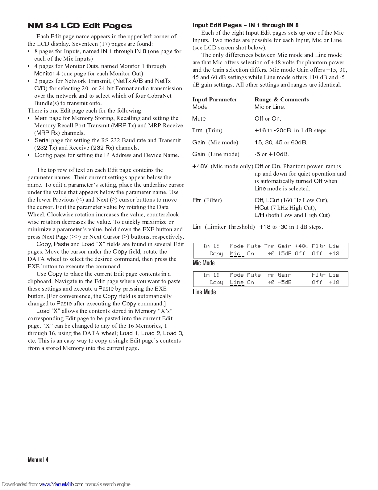
Setting up the Mic Preamplifier
No source should be connected at this time!
Make sure no signal will reach an amplifier!
1. Select the correct
Mode
(
Mic
or
Line
).
2. Set
+48
phantom power as required (
Mic Mode
only).
3. Estimate
the maximum signal level your source can produce.
4. Set the
Gain
parameter to a level that will not allow
clipping under worst case conditions (the clip point for the
preamplifier is +18 dBu).
5. Turn
Mute Off
6. Set Trim (
Trm
) to
0 dB.
7. Set Filter (
Fltr
) as required.
8.
Make sure no signal will reach an amplifier!
9. Connect your source.
10. Set the Limiter (
Lim
) to
+15
(3 dB below clipping).
11. If you can light the red
Limit
indicator,
reduce the
Gain
.
12. Remember, if you overload the Mic Input stage, the Trim
(
Trm
) and Limiter (
Lim
) settings are useless!
13. After the Input gain is set to prevent clipping under worst
case conditions, reduce the Trim (
Trm
) level to a conserva-
tive level and set the Limiter (
Lim
) threshold as required.
14. Repeat for each source in the system.
15. You are now ready for a sound check.
16. Remember, use the Trim (
Trm
) parameter for all level
adjustments during a live performance,
not
the
Gain
parameter. In a system with marginal gain-margin-stability,
adding an additional 15 dB of gain could result in nasty,
screaming oscillations. If you find that you do not have
enough gain range with the Trim level during a live
performance and must increase the Gain setting, be sure to
reduce the Trim by at least 12 dB before stepping up the
input Gain. You may then adjust the Trim as required.
The list looks long, but the idea is simple.
1) Make sure the Input cannot overload.
2) Use the
Trm
and
Lim
parameters to set and maintain levels.
The use of ActiveX controls allows the system designer to
build custom system control interfaces. While giving the end
users access to basic trim controls and memory recall func-
tions, they may be denied access to parameters that would
defeat your hard work.
Extra credit reading:
In addition to protection of equip-
ment and control of SPL, the NM 84 s Limiters may be used
for AGC. To provide AGC, set the Limiter (
Lim
) to a level
about 10 to 15 dB below your required operating level and
then use the Trim (
Trm
) for make-up gain.
Important Big Picture Concepts
There are several imperative concepts which must be
known to effectively understand the NM 84 and its CobraNet
technology. A few of these are discussed below. Reading the
rest of this manual and a thorough visit to
www.peakaudio.com/cobranet
are highly recommended.
NM 84 Memory scheme.
All Rane products that contain
Memories, including the NM 84, follow a common scheme:
The LCD display (or software screen for PC-controlled
devices) shows the current settings of the device. Sixteen
Memory locations (or some number, depending on the
product) exist from which the current device settings are
stored and recalled. The current settings are considered
Memory zero; some people like to think of Memory zero as
working Memory. All device editing is performed using
Memory zero even though we never display the number
zero. There are, therefore, actually 17 Memories 1 through
16 and zero.
Any changes made to the device are
immediately
stored in
Memory zero. Should there be a power interruption, the
contents of Memory zero are recalled upon power up from
their previous, pre-power-down settings. Thus, work in
progress is never lost and the device comes up with the same
settings with which it went down.
Once you are happy with the current settings in Memory
zero, they can be stored to one of the 16 Memories. To display
or edit a previously stored Memory, recall it into Memory
Zero. See the Memory Edit section on page Manual-6 for
more details.
Control data transmission
. In addition to the thousands
of audio Bundles available in CobraNet, additional network
data space is allocated in CobraNet for control data transmis-
sion. This non-Bundle space, if you will, is where the NM 84
transmits the Serial (RS-232) data and Memory data for the
MRP. This control data is transported asynchronously over
CobraNet (not isochronously like the audio data), although
with a theoretical maximum of 9 Mbits/sec there is little need
to worry about control data arrival times. This is only 468
times faster than 19200 serial control data!
CobraNet Bundles.
The NM 84 can access up to 999 of
the over 65,000 Bundles available (using Peak Audio s
CobraCad software, all 65,000 Bundles are accessible).
CobraNet divides the tens of thousands of Bundles into three
different Designations or types for the transport of audio data
over the network. The table on the next page explains the
differences between the three types of CobraNet Bundles.
There are advantages and disadvantages in using each. The
Network Examples section after the table discusses applica-
tions for the various Designations.

Manual-9
Bundle Transmission conflicts.
Do not transmit onto the
same undle from two different CobraNet devices.
Doing so
causes the loss of the data sent from the second device.
Firmware primer.
The NM 84 contains two pieces of
internal firmware. One is the CobraNet firmware for the
CobraNet interface, the second is the NM 84 s own internal
Rane firmware for the front panel interface, et cetera.
The Rane firmware revision number is displayed in the
NM 84 LCD display on the
top
line during power up. Both the
Rane firmware version (e.g.,
Ver ion 1.01
) and the date the
Rane firmware was compiled (e.g.,
Mar 21, 2000
) is dis-
played. Displaying the additional date is a good way to ensure
Y2K compliance. To update the Rane firmware, you must
replace an internal chip.
The CobraNet firmware version is displayed on the
bottom
line of the LCD display during power up (e.g.,
CobraNet rev
2.6.4
).
Interoperability between various CobraNet devices
requires matching CobraNet firmware versions.
CobraNet s
Disco utility provides the means to download new CobraNet
firmware into the NM 84. You must obtain Disco and the
required binary CobraNet firmware files separately. There is a
unique firmware file for each model of CobraNet device;
contact Rane for the latest CobraNet firmware if needed.
A on Network Hardware
. Before running out to your
nearest computer retailer for networking equipment, check out
the latest list of equipment blessed by Peak Audio at
www.peakaudio.com/cobranet/tested_products.htm
. (As a of
interest, a look through price lists will show you that the price
of a non-managed switch has come down close to the price of
a repeater hub.
You would be wise to spend the extra bucks
and go for the switch, as it will make your network more
flexible and expandable
.)
Four basic network hardware devices exist for use in
CobraNet network designs. The simplest, least expensive and
previously most common are called
repeater hubs
, which send
all incoming data out all of their network ports. Thus repeater
hubs are always multicast (broadcast) devices all data goes
everywhere. Use repeater hubs only when you have a dedi-
cated CobraNet network (no computers) and when all audio
channels are needed at all CobraNet node locations. If, for
audio security or other reasons, your application requires
certain channels to be accessible only in a certain area of the
network, you cannot use repeater hubs (use switched hubs).
Also, you cannot use repeater hubs in your network if you
need to share computer data and CobraNet data on the same
network. Repeater hubs are devices for freshmen, Network
rebmuneldnuBnoitangiseDnoitpircseDsegatnavdAsegatnavdasiD
)ffO(0
)00$:xeh(
lluNnoissimsnarT
desunU.delbasid
.ffO,.e.i,lennahc
gnivasdnaoiduagnitumroftcefreP
.htdiwdnabkrowten
sevirrarevenoiduadetuM
sidnanoitanitsedynata
.raehotelbissopmiylraen
552hguorht1
1000$:xeh(
)FF00$hguorht
eldnuBtsacitluMllA.tsacitluM
secivedteNarboC
&timsnartnac
hguorhtatadeviecer
.seldnuBtsacitluM
forebmundetimilnunaswollA
onhtiwnoissimsnartrepsreviecer
htdiwdnabkrowtenlanoitidda
.demusnoc
dnateNarboClla,krowtenteNarboCanO[
,sbuhretaepersahcus,secivedteNarboC-non
].atadtsacitluMllaeviecer
secruosersemusnoC
-krowten)htdiwdnab(
tsacitluM23ylnO.*ediw
repdewollaseldnuB
gnisunehwNALV
.sehctiwsdeganam
stroptibM01llaspmawS
.krowtenehtno
dexiF*[
gnisuseldnuB8fomumixam
tonoD.skrowtenbuhretaeper
teNarboCdnaatadretupmocxim
].krowtenretaeperanoatad
hguorht652
972,56
0010$:xeh(
)FFEF$hguorht
eldnuBtsacinU-tniop,.e.i(tsacinU
atad)tniop-ot
.noissimsnart
htiW[
PMNSsuoiresemos
seldnuBtsacinU,krow
tsacitlumsaputesebnac
naemtonseodsiht-
tiodotdeenrevell'uoy
yhwos
lasisihT.hguoht
].tsixeseldnuBtsacitluM
rebmunmumixamdexifonsierehT
.skrowtendehctiwsnoseldnuBfo
atadteNarboCdnaatadretupmoC
ylbailerdnayltneiciffeeromnac
yltaerG.krowtenemasehtnotsixe
tuphguorhtatadkrowtensevorpmi
ylnosiatadecnisycneiciffedna
tondn
atniopottniopmorfdessap
01swollA.ecivedkrowtenyreveot
.stroptibM
s'ecivedenodnestonnaC
enonahteromotoidua
gnisutuohtiwecivedrehto
tnednepednidnocesa
.eldnuB
swolla48MNehT[
ebotslennahCoiduA8emaseht
tnereffid4otpunodettimsnart
mumixamehtsihcihw-seldnuB
].secivedt
eNarboCybelbawolla
Table 1. CobraNet Bundles

Manual-10
101 designs. As with many technologies, repeater bus have
had their day and may soon be a thing of the past.
The second kind of network hardware devices are called
switched hubs which are only a little bit more expensive than
repeater hubs. Using switches for your network greatly
increases the efficiency of the network and allows computer
data to be shared on the network. Switches automatically
view the IP address (destination) of all incoming data and
only send the data out the single required port for delivery,
therefore, switches are unicast (point-to-point) devices.
Switches are the more common network hardware devices
used for CobraNet networks. Switched hubs are like the
Junior or Senior class of the network world.
A third type of network hardware is a managed switch.
Similar to a switch but the next step up the rung managed
switches can be user-configured in several ways: you can
create Virtual LANs (VLANs) and change the network
architecture among various VLAN setups; you can set the
managed switch up to prioritize the incoming data so audio
data has higher priority than computer data, for example. With
such capabilities, you can see that managed switches are not
simple, Networking 101 devices they re more like the
Ph.D. candidates of the network world.
The fourth network hardware device to introduce is called
a media converter. These are devices that convert the electri-
cal signal from a set of copper wires (e.g., CAT 5 cable) to the
light signal of the fiber optic world. Use media converters
when the distance between network nodes exceeds the 100
meter limitation of copper cable.
Delay Times.
There is an inherent delay between when
audio enters and exits a CobraNet network. For the NM 84,
the delay from when analog audio enters the device until it
appears at the analog output of another NM 84 on a typical,
small network is specified by three numbers. They are
CobraNet s fixed 5.33 milliseconds and the A/D and D/A
propagation delays all of which are specified separately on
the NM 84 Data Sheet. This allows calculating delay times
across the network. The A/D time gets you onto the network;
the network delay is fixed between any CobraNet devices; the
D/A time is the time between the arrival of the CobraNet
audio and the analog audio exiting from the Monitor Outputs
when they re configured to monitor Network audio. (See the
Peak Audio FAQ web page about the maximum number of
switch hops and delay times through network hardware
devices.)
Your application dictates whether this propagation delay is
acceptable or not. Most CobraNet applications won t have to
worry about this, but just to provide some insight, here s two
applications that may not like this delay. For example, a
theater with an elevated center cluster that provides coverage
eciveDerawdraHkrowteNsegatnavdAsnoitatimiL/segatnavdasiD
sbuhretaepeR
yeht,.e.i;xelpudflahetarepO
eviecer&
timsnarttonnac
001a,suhT.ylsuoenatlumis
tibM001sikrowtentibM
.ediw-krowten
.)yawagniogylekiltub(evisnepxe
niyreV
krowtenteNarboCdetacidedanehwtcefreP
llataderiuqersiatadoidualladnadedeensi
.sedonteNarboC
noatadr
etupmocroretupmocaecalptonnaC
gnisuatadteNarboChtiwkrowtenemaseht
8fomumixamdexifasierehT.sbuhretaeper
.
krowtenbuhretaeperanodettimrepseldnuB
tsumsecivedlla,skrowtenretaepernO
flahnidnaetaratademasehttaetare
po
retemaidkrowtenyebotsuM.edomxelpud
aotdeddaerasbuhretaepersA.snoitcirtser
sihtdiwdnabkrowteneht,krowt
en
.secivedkrowtenssorcaderahs/dedivid
)deganamnu(sehctiwS
gnilbanexelpudllufetarepO
dnatimsnartsuoenatlu
mis
tibM001,suhT.eviecer
hcaenitibM001eraskrowten
replatottibM002;noitcerid
!trophctiws
eht,krowtenaotdedd
aerasehctiwssA
emoS.sesaercnihtdiwdnabs'krowten
,.e.i(serutaefecnarelottluafedivorpsehctiws
rehtootsecaf
retnidna)sehctiwsdeganam
seigolonhcetkrowtenro)rebif,.e.i(aidem
snoitcirtserretemaidkrowtenoN.)MTA,.e.i
(
.)evahsbuhretaeperekil(
desab-hctiwsgnisU[
,snoisilloctcetedotdeens'teNarboCsevomerskrowten
-hctiws.svretaeperhtiwyltnereffidst
cateNarboCsuht
wonkottnatropmitonsisihthguohtla—skrowtendesab
].noitareporeporprongisedrofdnatsrednuro
retaepernahtevisnepxeeromylthgilsylnO
artxewef)yllaretil(ehthtrowllewsiti;sbuh
.buhretaeperanahthctiwsa
roferomsrallod
hctiwSdeganaM
ekilerasehctiwsdeganaM
yeht;sdioretsnosehctiws
puteselbazimotsucynamreffo
.se
rutaef
scitsongaid,puteselbixelfylemertxetimreP
hguohtlA.seitilibapacgnitoohselbuortdna
nahtevisnepxeero
merasehctiwsdeganam
seitilibapaceseht,sehctiwsdeganam-non
krowtennehwsevlesmehtrofyapnahterom
signitoohs
elbuortronoitarugifnoc-er
.putesgnirudylralucitrap,deriuqer
tub,sehctiwsdeganam-nonnahtyltsoceroM
oteuds
metsysynamrofesnepxeehthtrow
.segatnavdarieht
Table 2. Network Hardware

Manual-11
for listeners in the initial, center seats may not find this delay
acceptable. Assuming that no propagation delay is added
through other digital signal processing or a digital console
(this may be the case), the additional network delay of 6.5175
feet assuming NM 84s on and off the network may place
the arrival time of the direct sound versus the acoustic arrival
outside the Haas effect time. This would make the propagation
delay unacceptable for this application. If you re implement-
ing a mic snake type of application and are including the
monitor audio for stage members on the network, be sure to
not exceed an acceptable delay time; a delay time not much
more than 10 milliseconds (or hopefully less) is probably
acceptable for monitor applications. Decide for yourself.
That being said, there are upcoming technologies (i.e.,
vaporware) that may cut this network propagation time in half
or more. But, like most vaporware, we d have to kill you after
we told you about it. So, when this
really
becomes available,
we ll let you know. This way, we won t have to kill you now.
Cables.
Unlike simpler analog audio cable, choosing and
installing CAT 5 network cable and connectors can be
challenging and deceiving given that 100 megahertz data is
being transported. Plus, the connector termination is not
intuitively obvious; get it wrong and you ll spend hours
blaming equipment when it s the cables all along. (
I know this
because Ive spent a full day and a half suspecting equipment
when the cables were to blame. And yes, the cables had tested
fine with a continuity tester, but a continuity tester is nowhere
near good enough a test for the required 100 megahertz data
were talking about here.
) This cable stuff requires special
attention beyond that normally paid by us audio guys who are
now trying to implement these newfangled audio networks.
Do yourself a favor and visit Peak Audio s website where
they have a great primer on Network Cabling.
http://www.peakaudio.com/cobranet/network_cabling.htm.
Finding or training people to deal with network cable and
network troubleshooting is a worthwhile investment if your
future includes networked audio systems.
Remember that the network hardware devices chosen for
your network go hand in hand with the Bundles required to
deliver audio for a given application. Multicast networks/
Bundles can be transported over repeater hubs or over
switches; Unicast networks/Bundles require using switches.
You cannot transport unicast data over repeater hubs.
Although the Network Hardware (Table 2) and the
CobraNet Bundle (Table 1) are similar, they are listed sepa-
rately since, for example, multicast data can be transmitted
over repeater hubs or switches. Thus listing them separately
allows you to determine which approach is best for your given
application.
When observing the indicators on switch ports for
CobraNet devices, Rane NM devices appear as full duplex
devices. (Rave devices available from our friends at QSC
Audio appear as half duplex; this may change however, so
check with QSC.)
A Few Words About Networks
The opening primer in the Quick Start about designing a
network makes it sound so easy and it is, relatively but it s
like using three sentences to say
design a sound system for a
building
. Like many technologies, there is always something
new to learn. Networks and Ethernet may be new to audio
folks, but they re old news to computer types. Here are a few
good places on the Internet for more information on these
subjects:
Rane s main network help links page:
www.rane.com/ethernet.html
Network Design:
www.peakaudio.com/CobraNet/Network_Design.html
The folks at Peak Audio are, obviously, an invaluable
resource for CobraNet information. Do not underestimate
their interest in the success of your designs or their willing-
ness to help with network design or the myriad questions
that arise.
John s Closet - A down-to-earth set of networking how-
to s:
www.johnscloset.net
Ethernet Tutorial - A wonderful tutorial in plain English
from Lantronix:
www.lantronix.com/training/tutorials
Informit.com - Free online books about programming
include lots of Web stuff
Network Design Tutorials & Other Resources - An indus-
trial-strength link list of networking topics:
www.alaska.net/~research/Net/nwpages.htm
Ethernet Information - Network Basics / Cabling:
www.windowsnetworking.com/j_helmig/basics.htm

Manual-12
Network Examples
There are two ways to transmit CobraNet audio across a
network. An example for each transmission method follows.
The application dictates which of the two methods to use.
Some applications may require both methods simultaneously.
Multicast Net ork example [a.k.a. broadcast] requir-
ing simpler repeater hubs
One way to transmit audio over the network is to allow all
of a device s audio channels to be transmitted to all devices.
This is called
multicast
in network lingo and can be thought of
using the more familiar term: broadcast. Thus, when you
transmit audio using one of the
Multicast undles
(Bundles 1
through 255), the audio is broadcast to every device on the
network.
This broadcasting of all channels everywhere is required
for applications such as paging when emergency audio must
be delivered to every node. When users at each node need
independent access to all available audio channels, use
Multicast Bundles. If your application is a large music
complex with many audio channels and all the audio channels
are required in all rooms or nodes, use a multicast network by
selecting Multicast Bundles 1-255 for audio transmission.
One advantage when using Multicast Bundles is that an
unlimited number of receivers (CobraNet devices) are allowed
for a single transmission with no additional network band-
width being consumed. This is just like radio broadcasts: one
transmitter, unlimited receivers.
Another advantage is the lower cost and complexity
network that is required to implement the audio system using
Multicast Bundles which are implemented utilizing simple
Ethernet repeater hubs, which are quite inexpensive. This
makes this Multicast application and system a Networking
101 example inexpensive and easily implemented.
The disadvantages of Multicast Bundles include the loss of
bandwidth network-wide, since every device and every
network cable contains the same quantity of data. All
multicast data takes up the same amount of bandwidth
throughout the entire network. Another thing to be cautious of
is that multicast CobraNet data will swamp any 10 megabit
(10Base-T) data ports on the network.
Modern computers with 100 Mbit PCI Ethernet interfaces
(100Base-T) are quite capable of ignoring this multicast traffic
until their network connection becomes saturated. However, if
the computer is connected to the network via
10 Mbit Ethernet, that link will easily saturate. In any case, it
is not CobraNet which suffers under these conditions, it is the
computers.
The final disadvantage using multicast transmission is the
inability to
reliably
share computer network data and
CobraNet data on the same network. This is not to say that it
is impossible, it indeed works. However, the problem is that
the network bandwidth required by the computer data is ever-
changing and not controlled or monitored by the CobraNet
devices. Thus, when the computer data suddenly and unpre-
dictably requires more bandwidth than is available, the entire
network bogs down creating computer data collisions which
slow down the computer network, and simultaneously creates
audio dropouts, pops or ticks. Not fun, or necessary.
Oftentimes however, computer data must be shared on the
network or not all audio channels are required at every node.
This is where unicast networking comes in.
Unicast Net ork example [a.k.a. point-to-point]
using more flexible s itches
A second way to send audio over the network uses a
different scheme called
unicast
or point-to-point. You must
use unicast when you require only certain locations on the
network to receive certain channels. For example, in a
campus-sized church complex, it may be useful to send all
channels from the live band mics to the front of house (FOH)
mixer, monitor mix location
and
to the recording studio. But
the left-center-right (LCR) audio feed to the overflow building
across the street only needs three channels. The stereo FM
broadcast room only needs a stereo mix and the video truck
which is used only every other week may require all channels.
In the above case, it is not required, overly complex, and
most importantly, expensive to send all channels to all
locations. Thus, a unicast (point-to-point) network to feed the
mic channels from the stage to the four required locations
FOH, monitor, recording studio and video truck is required.
Therefore, using Bundles starting at 256 or above, sends the
audio over Unicast Bundles which forces the use of network
switches (not repeater hubs) which support unicast data.
For the LCR and stereo FM broadcast feeds, you could use
hard-wired cable runs which may be less expensive. Or, use a
single CAT 5 cable, three CobraNet devices and a couple of
dedicated repeater hubs and utilize a single Multicast Bundle
(1 through 255) to transmit all 5 audio channels to both the
remote LCR and FM locations from the front of the house.
Now let s make things fun and assume, since this church
pays no taxes, that their infinite budget (
so common these
days
) requires an audio system in the church s on-site hotel
and gymnasium. Oh, how fun.
The church s hotel, gymnasium and attached convention
center requires a dozen stereo channels of background music
as well as 4 paging audio feeds. Additionally, the LCR and
stereo feeds from the church are fed into the gymnasium and
convention center for more overflow on Christmas, Easter and
when Father Guido Sarducci is in town.
Including the 12 stereo background feeds on the network,
allows the church complex access to these background music
sources for intermissions and open houses.
I think you can see where this is going. By using a
combination of multicast and unicast networking, you can
easily use CobraNet technology to efficiently distribute many
audio channels to and from many locations and save consider-
able money on cable, conduit, labor and the re-configuration
time needed to accommodate the wide variety of audio
distribution needs in large and small facilities.
CobraNet network designs must not exceed 32 Multicast
Bundles per VLAN. A VLAN (virtual LAN) is an advanced,
Networking 401 term associated with managed switches
used on only the most advanced systems. Managed switches
allow point-to-point virtual LANs to be defined by the
network designer.

Manual-13
So tware and Applications
ActiveX and Soft are issues
Microsoft ActiveX controls (defined in the next section)
are of concern to the pro audio community. This technology
allows designers of computer-controlled sound systems to
create common front-end software control panels that operate
different manufacturers units, without having to know
anything about their internal code or algorithms. This is
powerful. When more manufacturers jump on the ActiveX
bandwagon, systems designers will no longer be limited by
the products offered by a single, platform-specific (i.e., closed
architecture) manufacturer.
What is ActiveX any ay?
ActiveX is a Microsoft-developed software technology
released in 1996. ActiveX, formerly called OLE (Object
Linking and Embedding), is loosely based on the Component
Object Model (COM), but provides substantially different
services to developers. At this point, you might think:
WHAT!?^* But keep reading! An ActiveX control is a unit of
executable code (such as an .EXE file) that follows the
ActiveX specification for providing software objects. This
technology allows programmers to assemble reusable software
controls into applications and services. However, software
development using ActiveX technology should not be
confused with Object-Oriented Programming (OOP). OOP is
concerned with creating objects, while ActiveX is concerned
with making objects work together. Simply stated, ActiveX is
a technology that lets a program (the ActiveX control) interact
with other programs over a network (e.g., the Internet or
Ethernet), regardless of the language in which they were
written. ActiveX controls can do similar things as Java, but
they are quite different. Java is a programming language,
while ActiveX controls can be written in any language (e.g.,
Visual Basic, C, C++, even Java). Also, ActiveX runs in a
variety of applications, while Java and Javascript usually run
only in Web browsers. ActiveX controls can be used in web
pages and within visual programming languages such as
Borland s Delphi, Sybase s PowerBuilder, Microsoft s Visual
Basic and even in tools such as Adobe s GoLive,
Macromedia s DreamWeaver and National Instrument s
LabVIEW.
In English, for our pro audio applications, ActiveX control
objects are the sliders, buttons, indicators and other graphical
screen entities. The objects have properties such as slider
position and slider range and on or off for buttons and
indicators, etc. Once the screen objects are chosen and placed,
further ActiveX controls can then be used to link the object s
properties to other ActiveX controls. Thus, allowing linking
an ActiveX slider to the ActiveX control for a device s level
control. Then moving the level control graphic slider subse-
quently varies the audio level and vice versa.
Each ActiveX control is made up of Properties and Events.
ActiveX control Properties are values associated with the
control, which might include such things as level settings,
mute condition and meter readings. ActiveX control Events
tell the computer something significant has happened, such as
a switch closure, button press or clip detection.
ActiveX allows the manufacturer to create an object (a
piece of software code) which fully describes a device, while
hiding the implementation details such as protocol from the
programmer. By hiding the communication details, there is no
longer a need for different manufacturers to agree on proto-
col. This lack of a protocol standard means that cooperation
between manufacturers is not required. It allows each manu-
facturer to choose the best protocol for their devices.
For example, no longer would you need to know that the
17th byte of a 32-byte status message meant that the unit s
second output channel was muted. With an ActiveX control,
you might simply refer to the device s output 2 mute status as
Device1.Out2Mute. See the RaneNote Emerging Standards
for Networked Audio System Control and Controlling
Audio Systems with ActiveX Controls over CobraNet and
other Ethernet-based Networks, both downloadable from the
Rane website Library.
Implementing ActiveX controls
An example might help clear this up. A few assumptions
are that a computer is used to control an audio system over an
Ethernet network and that something on the computer s screen
controls some function of the system. The basic idea is to
place controls on the computer screen and link them, using
ActiveX, to a parameter in the system. What s important here
is that only the controls required by the computer s end user
need be displayed. Additionally, more detailed interfaces
(hidden or password-protected web pages) can then be created
to provide any level of system parameter access desirable
from complete system control, to a lone system power button
or anything in-between. No longer are systems limited to the
number of security levels provided by vendor s software, nor
are you limited to controlling a single system parameter per
screen control. For example, you can link multiple ActiveX
controls to a single screen object, thus adjusting EQ level
simultaneously with master level control and limiter threshold.
You can also program actions when certain events occur, such
as triggering audio playback or turning a system off at a
certain time or adjusting delay time as the temperature
changes.
You can control different parameters inside the same
device from different computers on the network as well as
controlling the same parameter from multiple computers. This
is one of the major advantages of networks multiple control
locations will automatically be updated when changes are
made by any control location.
Microsoft FrontPage 2000 ActiveX Example
Many use Microsoft s FrontPage 2000 to create user
interface web pages for computer-controlled systems. These
web pages may or may not be accessible over the Internet.
Once you master the ActiveX concept, using FrontPage with
ActiveX provides literally an infinite number of programming
possibilities. More information about the NM 84 s ActiveX
controls and the ActiveX controls for Rane s RW 232 devices
is found in the sections on the next page.

Manual-14
NM 84 ActiveX Example
The short version of the FrontPage 2000 procedure used to
setup a web page with ActiveX controls for a Rane NM 84
device s parameters goes as follows:
Insert a Rane NM 84 ActiveX control in a new web page.
(This software/control ships with the unit or can be found on
our website. Running this NM 84 setup procedure registers
the Rane NM 84 ActiveX control with the computer used to
create the web page. Otherwise, no special icon or folder is
created after running the setup, so save time by
not
looking
for the NM 84 software/control other than from within
FrontPage s ActiveX list.) Set the inserted NM 84 control s
Properties for your application. Generally, from FrontPage s
ActiveX Control Properties
window, this involves providing a
unique
Name
in the
Object
Tag
tab for the control. Then, link
this control to the specific NM 84 device by entering the NM
84 device s
IP address
in the
NM 84 SNMP Control Setting
tab. The NM 84 control also must be assigned an update rate
which is found on the
NM 84 SNMP Control Setting
tab. A
good default value might be 5 which provide an update
every half second. Don t get overzealous with this update rate
since it s a function of many things and can negatively effect
the speed at which controls and parameter changes take effect.
Next, insert an ActiveX slider, button or what have you
from the vast list of available ActiveX controls. If you can t
find a control that suits your fancy, further ActiveX controls
can be found on the Internet as shareware, bought from
ActiveX providers often in packages or created from scratch
for complete customization. Adjust the size, orientation and
placement of the control for optimum ergonomics being sure
to consider the user, the application and the requirement for
further controls on this same page. Keeping the number of
total controls on any one page low is very wise. See why in
the September, 2000 AES preprint by Rane s Stephen
Macatee and Devin Cook titled
Controlling Audio Systems
With ActiveX Controls Over CobraNet And Other Ethernet-
ased Networks
.
In the
ActiveX Control Properties
window for the slider
(or button), uniquely
Name
the control in the
Object
Tag
tab. Then in the
Parameters
tab, set the control s maximum
and minimum value to match the NM 84 device s parameter
that you ll link to this slider. Sometimes you ll find that you ll
need to adjust these maximum and minimum values here (or
in the Script language discussed next) to properly display or
be compatible with the parameter being adjusted. For ex-
ample, the Mic_Trim ActiveX control has a minimum value
of 0 and a maximum of 36, but the actual displayed range
of the Trim control is -20 to +16 dB in 1 dB steps. Thus, there
are 36, 1 dB steps. Also, often the control link may be
backwards such that the maximum value may correspond to
the lowest slider position. Fix this when updating the
control by subtracting the control s maximum setting from the
desired setting within FrontPage s VBScript language.
To link the slider to the desired NM 84 internal device
parameter, use Microsoft s VB Script language by associating
the slider s Name with the specific NM 84 Control Name.
You ll find the list of valid NM 84 ActiveX Control Names at
the end of this Manual.
To track slider or system changes and update either the
web page, the NM 84 device, or both, we ll need to use
Microsoft s Visual Basic Script language. This is where the
programming comes in. Yes, it does say
programming
.
Remember when you could do your job without the need to
program anything except the time on your wind up watch?
Some programming tasks here are things like initializing the
controls with valid information usually by reading the NM 84
device s current settings, then updating the on-screen controls
so they match the device. You also need the Script software to
scan for any changes and make updates accordingly. It is also
wise to be sure that any requested changes to parameter values
are within the proper numerical range, thus avoiding strange
and unpredictable behavior. This is usually called bounds
checking by programmers. Since these web page and
network technologies allow multiple control locations, be sure
your code handles this. For example, NM 84 device param-
eters can be changed from the NM 84 s front panel, from the
web page itself, from another copy of the same web page
being run elsewhere on the network, or changes can also be
made from contact closure memories. Take this into account
when writing the update settings code by scanning indepen-
dently for changes to the device s settings and changes to the
web page controls. Then update things so the device settings
and the web page controls always match. The Rane has
example code with comments.

Manual-15
Computer IP Setup
If you re using a computer with the NM 84, it must be set
for network operation to allow it to speak using TCP/IP
protocol. (TCP stands for Transmission Control Protocol.) If
your computer is already set up for network operation you can
move on in your life and skip this section.
Windo s 95/98 PC Net ork Communications Setup
As you go through the following procedure your computer
tells you (on more than one occasion) that it needs to reboot
before changes take effect. Just go along with it when this
happens. Yeah, its a big waste of time but this is an owners
manual, not an editorial page so just do it, OK?
1. Insure you have a functional Ethernet adapter (NIC or
Network Interface Card) installed in the PC. If installed, its
operation may be checked by right clicking on
My Com-
puter
followed by a left-click on the selection
Propertie
and again a left-click on the
Device Manager
tab of the
Sy tem Propertie
dialog box. Click on the plus (+) sign
to the left of
Network Adapter
to view the configured
adapters. A malfunctioning adapter is indicated by either a
yellow question mark or a red
X
. There are several
troubleshooting aids available in Win-dows Help to assist
you in making the network adapter functional.
2. Once you have a correctly operating Ethernet adapter, TCP/
IP is easy to configure. To begin, open
My Computer
or
Start > Setting
, then
Control Panel > Network
. The
Configuration
tab shows a list of configured devices,
such as your network card and possibly dial-up networking.
Below these is a list of network protocols previously
configured for the system. If TCP/IP has been configured
and bound to the Ethernet adapter, you will see an entry
resembling
TCP/IP -> NameOfAdapter Pnp LAN
Adapter.
If this shows on the list, skip to step 4. If it s not
there, go through step 3 first.
3. To add TCP/IP to the LAN Adapter, click the
Add
button
in the Network dialog. A list of network component types
displays. Choose
Protocol
, then
Add
. A list of manufac-
turers displays. Click on
Micro oft
, then
TCP/IP
in the
right-hand window, then
OK
.
4. To be a part of a TCP/IP network, your computer (and each
network device including the NM 84) needs a unique IP
address of its own. If not already open, open
Setting >
Control Panel > Network
. Highlight the
TCP/IP ->
NameOfAdapter PnP LAN Adapter
by clicking on it.
Then choose
Propertie > IP Addre
. Click on the
Specify an IP addre
option. If your computer
is
part of
an existing network, you must now obtain a valid address
from the network administratorif you have one. If not,
you may use an address out of the internationally accepted
private network block of addresses, which is
192.168.nnn.nnn where nnn represents any number
between 0 and 255. A good choice might be
192.168.100.100 just because it s easy to remember if you
ever need to know it again. Set the
Subnet Ma k
to
255.255.0.0 for most installations. These two settings allow
a network with addresses in the range of 192.168.0.0
through 192.168.255.255. Click the
OK
buttons as many
times as they appear to extinguish all the network setup
dialog boxes.
Once youve set networking on a Win95/98 computer, youll
notice it wants a user name and optional password each time
it boots. To eliminate this nuisance, go back in to
Control
Panel > Network
and change the
Primary Network Logo
n
selection from
Client for Microsoft Network
s to
Windows
Logo
n then click
O
K again. Oh, and guess what? Your
computer will want to be rebooted again for the change to
take effect. Good news, though, it wont ask for a user name
and password this time.
Glossary o Terms
As with any technology, new terms are thrown about like a
hot Mr. Potatohead at a 5 year old s birthday party. The
CobraNet website (
www.peakaudio.com/cobranet
) is a
valuable resource for such jargon and includes a Terminology
page for CobraNet terms. Here are a few just to keep things
going.
Asynchronous
Not synchronized by a shared signal such as
a clock or semaphore, proceeding independently. Email and
computer file transfers are examples of asynchronous data
streams.
Audio Channel
This is an ambiguous term, but defines a
single channel of audio in a CobraNet network; the capital
letters. (The term formerly known as
Sub-channel
.)
Broadcast
See Broadcast addressing.
Broadcast addressing
A special case of Multicast address-
ing. Whereas it is possible, in some cases, to indicate
intended recipients of multicast data, broadcast data is
unconditionally received by all devices within a network.
Bundle
A group of up to 8 Audio Channels. To transport
audio over an Ethernet network, CobraNet places up to 8
Audio Channels in Bundles. (The term formerly known as
Network Channel
.)
Concentrator
A Repeater Hub, Switching Hub or passive
interconnect such as a Patch Panel. Concentrator is less
technically concise than Hub.
CobraNet
A Peak Audio technology, CobraNet is a
combination of hardware, software and protocol which
distributes many channels of digital audio over Fast
Ethernet. CobraNet supports switched and repeater Ethernet
networks. On a repeater network, CobraNet eliminates
collisions and allows full bandwidth utilization of the
network. CobraNet uses standard Ethernet packets and
network infrastructure.
CobraNet node
Any network device which is in compli-
ance with the CobraNet specification for transmission and/
or reception of digital audio and associated sample clock.
CobraNet port
The same as CobraNet node, but more
specifically, the RJ-45 connector on a CobraNet device.

Manual-16
Conductor
The CobraNet device on the network which
supplies the master clock. A conductor arbitration proce-
dure insures that at any time there is one, and only one,
conductor per network. The conductor transmits beat
packets at a regular interval. The time interval between beat
packet transmission is the mechanism of clock delivery.
The conductor is also responsible for generating transmis-
sion permissions based on forward reservations received in
reservation packets. The transmission permissions are
published in the beat packet.
Crossover cable
A special network cable that allows two
network devices to connect directly together without the
need for a hub. The receive and transmit pairs must be
swapped within the cable.
One End Cable the Other End
TR+ pin 1 pin 3 RCV+
TR- pin 2 pin 6 RCV-
RCV+ pin 3 pin 1 TR+
RCV- pin 6 pin 2 TR-
Since a normal (non-crossover) network cable physically
looks like a crossover cable, one of three practices are
suggested: clearly label all crossover cables so they are not
confused with normal standard ethernet cables. Wire two
female wall plate jacks back to back with the proper
swapping and use this adapter as a 2 port hub. Another
useful adapter uses a standard RJ-45 at one end and a
female wall jack at the other cross-wired. Making these two
adapters short helps avoid confusing standard network
cables from crossover cables.
http://www.peakaudio.com/
cobranet/network_cabling.htm.
Fully Switched Network
A network built entirely from
Switching Hubs. With the elimination of Repeater Hubs,
the collision condition is removed from a fully switched
network.
Hub
Hub is not a technically concise term. The term can be
used to refer to either a Repeater Hub or a Switching Hub.
Isochronous
Uniform in time; of equal time; performed in
equal times; recurring at regular intervals. An isochronous
data stream is characterized by the fact that data delivered
late is unusable. Live audio and video are examples of
isochronous data streams.
Media Converter
A two port Repeater Hub with different
media types on each port. Media converters can convert
between CAT5 Cable and Fiber.
Multicast
See Multicast addressing.
Multicast addressing
Data which is Multicast is addressed
to a group of, or all devices on a network. All devices
receive multicast addressed data and decide individually
whether the data is relevant to them. A Switched Hub is
typically not able to determine appropriate destination port
or ports for multicast data and thus must send the data out
all ports simultaneously just as a Repeater Hub does.
Multicast addressing is to be avoided whenever possible
since it uses bandwidth network wide and since all devices
are burdened with having to decide whether multicast data
is relevant to them.
Network Channel
Old term now called Bundle. (Hey,
Bundle is a Peak Audio term, so call them.)
Packet
A series of bits containing data and control informa-
tion, source and destination addresses and formatted for
transmission from one node to another.
Performer
All units except the conductor operate as a
performer. A performer must re-synthesize a sample clock
based on arrival times of received beat packets. A per-
former may transmit isochronous data packets only if given
transmission permission to do so by the conductor.
Repeater Hub
An Ethernet multi-port repeater. A data
signal arriving in any port is electrically regenerated and
reproduced out all other ports on the hub. A repeater hub
does not buffer or interpret the data passing through it. If
data signals arrive simultaneously from multiple ports, a
collision condition is recognized by the hub and a special
jam signal is transmitted out all ports.
Repeater Network
A network built with one or more
Repeater Hubs. Repeater networks share the same band-
width among all connected DTEs.
Sub-channel
Old term now called Audio Channel.
Switched Network
A network built with one or more
Switching Hubs. It is possible, even common to build a
network from a combination of interconnected Repeater
Hubs and Switched Hubs.
Switching Hub
- A Switching Hub, or simply "Switch",
examines addressing fields on data arriving at each port and
attempts to direct the data out the port or ports to which the
data is addressed. Data may be buffered within the Switch-
ing Hub to avoid the collision condition experienced within
a Repeater Hub. A network utilizing Switching Hubs
realizes higher overall bandwidth capacity since data may
be received through multiple ports simultaneously without
conflict.
Unicast
See Unicast addressing.
Unicast addressing
Data which is unicast is addressed to a
specific network device. A switching hub examines the
unicast address field of the data and determines on which
port the addressed device resides and directs the data out
only that port. Delivery of an email message is an example
of unicast data addressing.

Manual-17
Memory Recall Port
The MEMORY RECALL PORT (MRP) provides contact
closure control to recall any of the 16 Memories. Eight of the
Memories are recalled with individual switch closures to a
single terminal (see the Normal section of Table 1). Memories
in multiple units may be recalled by either connecting the
MRP terminals in parallel or by transmitting the MRP contact
closure over the network. See the Memory Edit Page section
of this manual.
Rane Firmware version 1.01 functions as follows: Only
momentary switches should be used since only single closures
are recognized. The NM 84 MRP is
not
read after power up,
therefore, changes to the switch states will not be updated
until the MRP conditions are changed when the power is on.
If more than one terminal is grounded at a time, only the first
closed switch is recognized. Subsequent switches are ignored
once the first switch is and remains closed. If multiple
switches are closed, once a single switch remains closed will
that memory be recalled.
However, certain combinations of terminals may be
grounded to activate Paging or Binary modes (see table). A
Binary mode allows access to all 16 Memories. For ex-
ample, connect the four contacts of a binary switch, plus the
additional Binary mode closures shown in the Table. Paging
mode provides an easy way to configure a system which uses
a single switch (such as a mic or key switch) to toggle
between two sequential Memories (See table). When wiring
contacts,
only use Normal, Paging or inary mode do not
switch between modes.
1 2 3 4 5 6 7 8 edoM tluseR
10000000 1
01000000 2
00 100000 3
000 10000 4
0000 1000 5
00000 10 0 6
000000 10 7
0000000 18
00000 111 1
1 0 0 0 0 1 1 1 2
0 1 0 0 0 1 1 1 3
1 1 0 0 0 1 1 1 4
0 0 1 0 0 1 1 1 5
1 0 1 0 0 1 1 1 6
0 0 0 1 0 1 1 1 7
1 0 0 1 0 1 1 1 8
0000 1111 9
1 0 0 0 1 1 1 1 01
0 0 0 0 1 1 0 1 1
10 0 0 1 1 0 1 2
0 1 0 0 1 1 0 1 3
110 0 1 1 0 1 4
0 0 1 0 1 1 0 1 5
10 1 0 1 1 0 1 6
0 1 1 0 1 1 0 1 7
1110 1 1 0 1 8
0 0 0 1 1 1 0 1 9
10 0 1 1 1 0 1 01
0 1 0 1 1 1 0 1 11
1 1 0 1 1 1 0 1 21
00 1 1 1 1 0 1 31
10 1 1 1 1 0 1 41
0 1 1 1 1 1 0 1 51
1 1 1 1 1 1 0 1 61
MRP Binary Control
1 = switch closed between COM and 1,2,3,etc.)
0 = switch open
MRP Wiring
NORMALPAGINGBINARY
87654321C
Mic
Switch
Memory
Switch
Paging
Mode

Manual-18
Control Name: Rane Corporation NM 84 SNMP Active X Control
Description: SNMP Control of a NM 84
Design Time Parameters:
IP Address NM 84s Device Address
Update Fre How often (in 100ms steps) the NM 84s status is checked
Runtime Parameters:
condPriority Conductor Priority ( 0 = Never Conductor, 32 = Default )
Conductor (Read Only) return TRUE if the NM 84 is currently the conductor
Online (Read Only) returns TRUE if the NM 84 is currently operational
: for Idx 0->7 corresponds to Input 1-8
Mic_Mute(Idx) TRUE/FALSE for Mic Mute setting
Mic_Phantom_Power(Idx) TRUE/FALSE for Mic Phantom Power setting
Mic_Line_Mode(Idx) TRUE/FALSE for Line Mode setting
Mic_Mic_Gain(Idx) (0 = 15dB, 1=30dB, 2=45dB, 3=60dB) for Mic Gain setting
Mic_Line_Gain(Idx) (0 =-5dB, 1=+10dB) for Line Gain setting
Mic_Trim(Idx) (0 =-20dB, 1=-19dB..36=0dB) for Trim setting
Mic_Filter(Idx) (0 =Off, 1=Low Cut, 2=High Cut, 3=High/Low Cut) for Filter setting
Mic_Limiter(Idx) (0 =+18dB,1=+18,48=-30dB) for Limiter setting
Mic1_Mute E uates to Mic_Mute(0)
Mic1_Phantom_Power E uates to Mic_Phantom_Power(0)
Mic1_Line_Mode E uates to Mic_Line_Mode(0)
Mic1_Mic_Gain E uates to Mic_Gain(0)
Mic1_Line_Gain E uates to Mic_Line_Gain(0)
Mic1_Trim E uates to Mic_Trim(0)
Mic1_Filter E uates to Mic_Filter(0)
Mic1_Limiter E uates to Mic_Limiter(0)
Mic2_Mute E uates to Mic_Mute(1)
Mic2_Phantom_Power E uates to Mic_Phantom_Power(1)
Mic2_Line_Mode E uates to Mic_Line_Mode(1)
Mic2_Mic_Gain E uates to Mic_Gain(1)
Mic2_Line_Gain E uates to Mic_Line_Gain(1)
Mic2_Trim E uates to Mic_Trim(1)
Mic2_Filter E uates to Mic_Filter(1)
Mic2_Limiter E uates to Mic_Limiter(1)
Mic3_Mute E uates to Mic_Mute(2)
Mic3_Phantom_Power E uates to Mic_Phantom_Power(2)
Mic3_Line_Mode E uates to Mic_Line_Mode(2)
Mic3_Mic_Gain E uates to Mic_Gain(2)
Mic3_Line_Gain E uates to Mic_Line_Gain(2)
Mic3_Trim E uates to Mic_Trim(2)
Mic3_Filter E uates to Mic_Filter(2)
Mic3_Limiter E uates to Mic_Limiter(2)
Mic4_Mute E uates to Mic_Mute(3)
Mic4_Phantom_Power E uates to Mic_Phantom_Power(3)
Mic4_Line_Mode E uates to Mic_Line_Mode(3)
Mic4_Mic_Gain E uates to Mic_Gain(3)
Mic4_Line_Gain E uates to Mic_Line_Gain(3)
Mic4_Trim E uates to Mic_Trim(3)
Mic4_Filter E uates to Mic_Filter(3)
Mic4_Limiter E uates to Mic_Limiter(3)
Mic5_Mute E uates to Mic_Mute(4)
Mic5_Phantom_Power E uates to Mic_Phantom_Power(4)
Mic5_Line_Mode E uates to Mic_Line_Mode(4)
Mic5_Mic_Gain E uates to Mic_Gain(4)
Mic5_Line_Gain E uates to Mic_Line_Gain(4)
Mic5_Trim E uates to Mic_Trim(4)

Manual-19
©Rane Corporation 10802 47th Ave. W., Mukilteo WA 98275-5098
TEL 425-355-6000 FAX 425-347-7757 WEB www.rane.com
Mic5_Filter E uates to Mic_Filter(4)
Mic5_Limiter E uates to Mic_Limiter(4)
Mic6_Mute E uates to Mic_Mute(5)
Mic6_Phantom_Power E uates to Mic_Phantom_Power(5)
Mic6_Line_Mode E uates to Mic_Line_Mode(5)
Mic6_Mic_Gain E uates to Mic_Gain(5)
Mic6_Line_Gain E uates to Mic_Line_Gain(5)
Mic6_Trim E uates to Mic_Trim(5)
Mic6_Filter E uates to Mic_Filter(5)
Mic6_Limiter E uates to Mic_Limiter(5)
Mic7_Mute E uates to Mic_Mute(6)
Mic7_Phantom_Power E uates to Mic_Phantom_Power(6)
Mic7_Line_Mode E uates to Mic_Line_Mode(6)
Mic7_Mic_Gain E uates to Mic_Gain(6)
Mic7_Line_Gain E uates to Mic_Line_Gain(6)
Mic7_Trim E uates to Mic_Trim(6)
Mic7_Filter E uates to Mic_Filter(6)
Mic7_Limiter E uates to Mic_Limiter(6)
Mic8_Mute E uates to Mic_Mute(7)
Mic8_Phantom_Power E uates to Mic_Phantom_Power(7)
Mic8_Line_Mode E uates to Mic_Line_Mode(7)
Mic8_Mic_Gain E uates to Mic_Gain(7)
Mic8_Line_Gain E uates to Mic_Line_Gain(7)
Mic8_Trim E uates to Mic_Trim(7)
Mic8_Filter E uates to Mic_Filter(7)
Mic8_Limiter E uates to Mic_Limiter(7)
: for Idx 0->3 corresponds to Monitor 1-4
Out_Local(Idx) TRUE/FALSE for Monitor Local setting
Out_Mic_Index(Idx) (0=Off,1=Input 1,,8=Input 8) for Monitor Local Mic setting
Out_Bundle(Idx) Bundle (a.k.a. Network Channel) to Receive
Out_AudioChannel(Idx) (0..7) Network AudChannel to Receive
Out1_Local E uates to Out_Local(0)
Out1_Mic_Index E uates to Out_Mic_Index(0)
Out1_Bundle E uates to Out_Channel(0)
Out1_AudioChannel E uates to Out_AudChannel(0)
Out2_Local E uates to Out_Local(1)
Out2_Mic_Index E uates to Out_Mic_Index(1)
Out2_Bundle E uates to Out_Channel(1)
Out2_AudioChannel E uates to Out_AudChannel(1)
Out3_Local E uates to Out_Local(2)
Out3_Mic_Index E uates to Out_Mic_Index(2)
Out3_Bundle E uates to Out_Channel(2)
Out3_AudioChannel E uates to Out_AudChannel(2)
Out4_Local E uates to Out_Local(3)
Out4_Mic_Index E uates to Out_Mic_Index(3)
Out4_Bundle E uates to Out_Channel(3)
Out4_AudioChannel E uates to Out_AudChannel(3)
TXAB_24Bits TRUE/FALSE for NetTx A/B 24 Bit Format Mode
TXCD_24Bits TRUE/FALSE for NetTx C/D 24 Bit Format Mode
TXAB_Split (0=1/7,,6=7/1) for NetTx A/B AudChannel splitting
TXCD_Split (0=1/7,,6=7/1) for NetTx C/D AudChannel splitting
TXA_Bundle NetTx As Bundle
TXB_Bundle NetTx Bs Bundle
TXC_Bundle NetTx Cs Bundle
TXD_Bundle NetTx Ds Bundle
108213
Other manuals for NM 84
1
Table of contents
Other Rane Amplifier manuals