Ranger Products RL4500 User manual

Forward this manual to all operators.
Failure to operate this equipment as
directed may cause injury or death.
MODEL RL4500
COMBINATION
BRAKE LATHE
FOR RESURFACING
AUTOMOBILE
AND LIGHT TRUCK
DRUMS, ROTORS
AND FLYWHEELS
INSTALLATION AND OPERATION MANUAL
SHIPPING DAMAGE CLAIMS
When this equipment is shipped, title passes to the
purchaser upon receipt from the carrier.
Consequently, claims for the material damaged in
shipment must be made by the purchaser against the
transportation company at the time shipment is
received.
BE SAFE
Your new Ranger brake lathe was designed and
built with safety in mind. However, your overall
safety can be increased by proper training and
thoughtful operation on the part of the operator.
DO NOT operate or repair this equipment
without reading this manual and the important
safety instructions shown inside.
1645 Lemonwood Dr.
Santa Paula, CA. 93060, USA
Tel: 1-805-933-9970
Fax: 1-805-933-9160
Keep this operation manual near the
machine at all times. Make sure that
ALL USERS read this manual .

TABLE OF CONTENTS
Contents Page No.
Owner’s Responsibility . . . . . . . . . . . . . . . . . . . . . . . .3
Definitions of Hazard Levels . . . . . . . . . . . . . . . . . . . . 3
Warning Instructions . . . . . . . . . . . . . . . . . . . . . . . . . . 4
Before You Begin . . . . . . . . . . . . . . . . . . . . . . . . . . . . .4
Electrical Requirements . . . . . . . . . . . . . . . . . . . . . . . .4
Important Safety Instructions . . . . . . . . . . . . . . . . . . . . 5
Features . . . . . . . . . . . . . . . . . . . . . . . . . . . . . . . . . . . 6
Specifications . . . . . . . . . . . . . . . . . . . . . . . . . . . . . . .6
Assembly View . . . . . . . . . . . . . . . . . . . . . . . . . . . . . .7
Installation . . . . . . . . . . . . . . . . . . . . . . . . . . . . . .8
Brake Rotor/Drum Inspection. . . . . . . . . . . . . . . . . . .8
Basic Operation. . . . . . . . . . . . . . . . . . . . . . . . . . .8
Reconditioning Brake Drums / Start. . . . . . . . . . . . . . . .9
Mounting Hubbed Brake Drums. . . . . . . . . . . . . . . .10
Mounting Hubless Brake Drums. . . . . . . . . . . . . . . . . . .10
Reconditioning Brake Drums Continued . . . . . . . . . .11
Brake Drums / First Scratch Cut . . . . . . . . . . . . . . . .11
Brake Drums / Determine Depth of Cut . . . . . . . . . . . .12
Reconditioning Brake Rotors / Start. . . . . . . . . . . . .13
Mounting Hubbed Brake Rotors . . . . . . . . . . . . . . . . . .13
Mounting Hubless Brake Rotors. . . . . . . . . . . . . . . . .14
Reconditioning Brake Rotors / Continued . . . . . . .14 - 16
Reconditioning Flywheels . . . . . . . . . . . . . . . . . .17
Adjusting Spindle Speed . . . . . . . . . . . . . . . . . . . .17
Installation Floor Space . . . . . . . . . . . . . . . . . . . .18
Maintenance . . . . . . . . . . . . . . . . . . . . . . . . . . .18
Parts Listing / Cross Feed Group . . . . . . . . . . . . . . .19
Parts Listing / Spindle Group Assembly. . . . . . . . . . .20
Parts Listing / Micro-Dial Group . . . . . . . . . . . . . . . . . 21
Parts Listing / Variable Speed Gearbox. . . . . . . . . . .22
Parts Listing / Cross Feed Assembly. . . . . . . . . . . . .23
Parts Listing / Motor - Drive Group. . . . . . . . . . .22
Failure to follow danger, warning, and caution
instructions may lead to serious personal injury or death
to operator or bystander or damage to property.
Do not operate this machine until you read and
understand all the dangers, warnings and cautions
in this manual.
For additional copies
or further information, contact:
Bend-Pak Inc. / Ranger Products
1645 Lemonwood Dr.,
Santa Paula, CA. 93060
1-805-933-9970
www.bendpak.com
OPERATOR PROTECTIVE
EQUIPMENT
Personal protective equipment helps make brake service
safer. However, equipment does not take the place of safe
operating practices. Always wear durable work clothing
during service activity. Shop aprons or shop coats may
also be worn, however loose fitting clothing should be
avoided. Tight fitting leather gloves are recommended to
protect operators hands when handling brake parts.
Sturdy leather work shoes with steel toes and oil resistant
soles should be used by all service personnel to help
prevent injury in typical shop activities. Eye protection is
essential during rotor resurfacing. Safety glasses with side
shields, goggles, or face shields are acceptable. Back
belts provide support during lifting activities and are also
helpful in providing operator protection. Consideration
should also be given to the use of hearing protection if
brake service activity is performed in an enclosed area, or
if noise levels are high.
THIS SYMBOL POINTS OUT IMPORTANT SAFETY INSTRUCTIONS WHICH IF NOT FOLLOWED
COULD ENDANGER THE PERSONAL SAFETY AND/OR PROPERTY OF YOURSELF AND OTHERS
AND CAN CAUSE PERSONAL INJURY OR DEATH. READ AND FOLLOW ALL INSTRUCTIONS IN
THIS MANUAL BEFORE ATTEMPTING TO OPERATE THIS MACHINE.
2

DEFINITIONS OF
HAZARD LEVELS
Identify the hazard levels used in this manual with the
following definitions and signal words:
DANGER
Watch for this symbol: It Means: Immediate hazards
which will result in severe personal injury or death.
WARNING
Watch for this symbol: It Means: Hazards or unsafe
practices which could result in severe personal injury or
death.
CAUTION
Watch for this symbol: It Means: Hazards or unsafe
practices which may result in minor personal injury or
product or property damage.
Watch for this symbol! It means BE ALERT!
Your safety, or the safety of others, is involved!
OWNER’S RESPONSIBILITY
To maintain machine and user safety, the responsibility of
the owner is to read and follow these instructions:
Follow all installation instructions.
Make sure installation conforms to all applicable Local,
State, and Federal Codes, Rules, and Regulations; such
as State and Federal OSHA Regulations and Electrical
Codes.
Carefully check the unit for correct initial function.
Read and follow the safety instructions. Keep them
readily available for machine operators.
Make certain all operators are properly trained, know
how to safely and correctly operate the unit, and are
properly supervised.
Allow unit operation only with all parts in place and
operating safely.
Carefully inspect the unit on a regular basis and
perform all maintenance as required.
Service and maintain the unit only with authorized or
approved replacement parts.
Keep all instructions permanently with the unit and all
decals on the unit clean and visible.
3

WARNING INSTRUCTIONS
1. This equipment incorporates parts such as electrical
switches which tend to produce sparks. When located in a
service facility, the unit should be in a ventilated room or
enclosure provided for the purpose, or should be at least 18
inches or more above floor to minimize the risk of igniting
fuel vapors.
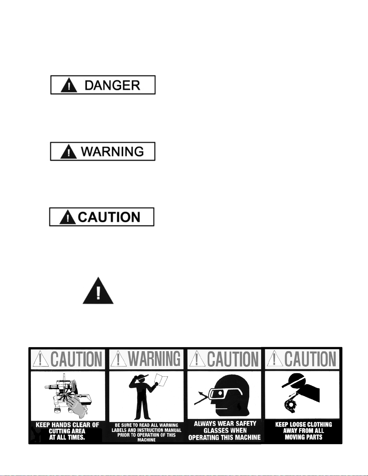
2. Eye and face protection is required and strongly
recommended: “Protective eye and face equipment is
required to be used where there is a reasonable probability
of injury that can be prevented by use of such equipment.”
OSHA1910.133 (a) Protective goggles, safety glasses, or a
face shield must be provided by the purchaser/user and
worn by the operator of the equipment. Make sure all eye
and face safety precautions are followed by the operator(s).
Keep bystanders out of the area.
3. Do not remove any safety equipment such as guards,
control switches or shut-off devices.
4. Make sure rotors are properly mounted and square
before starting the lathe. Check to make sure all parts are
secure.
5. Make sure the rotors are clean and mounted properly
before attaching lathe to the caliper.
6. Do not overload the lathe. Read and understand the lathe
capabilities prior to operation. Overloading the lathe can
shorten the lifespan of the unit, and could cause a failure
resulting in personal injury.
7. Check damaged parts carefully. Before further use of the
lathe, a guard or other part that is damaged should be
carefully checked. Immediately replace all damaged,
missing, or non-functional parts. Check for alignment of
moving parts, binding of moving parts, breakage of parts,
mounting, and any other conditions that may affect
operation. Guards and other parts that are damaged should
be properly repaired or replaced before lathe is used again.
8. Always feed the blade or cutter into the work and against
the direction of rotation. Cutters and tool bits are designed
to begin the cut from near the center of the rotor to the outer
edge. Do not attempt to cut from the outside edge into the
center.
9. Never leave the brake lathe running unattended. Turn the
power off. Don’t leave the brake lathe until the power switch
is turned to the OFF position.
10. Never use compressed air to blow and clear chips.
Chips and dust may be driven between machined parts and
into bearings, causing undue wear. They may also contact
persons in the area causing personal injury.
BEFORE YOU BEGIN
Receiving:
The shipment should be thoroughly inspected as soon as it
is received. The signed bill of lading is acknowledgement by
the carrier of receipt in good condition of shipment covered
by your invoice. If any of the goods called for on this bill of
lading are shorted or damaged, do not accept them until the
carrier makes a notation on the freight bill of the shorted or
damaged goods. Do this for your own protection.
NOTIFY THE CARRIER AT ONCE if any hidden loss or
damage is discovered after receipt and request the carrier
to make an inspection. If the carrier will not do so, prepare
a signed statement to the effect that you have notified the
carrier (on a specific date) and that the carrier has failed to
comply with your request.
IT IS DIFFICULT TO COLLECT FOR LOSS OR DAM-AGE
AFTER YOU HAVE GIVEN THE CARRIER A CLEAR
RECEIPT. File your claim with the carrier promptly. Support
your claim with copies of the bill of lading, freight bill,
invoice, and photographs, if available. Our willingness to
assist in helping you process your claim does not make
Ranger Products responsible for collection of claims or
replacement of lost or damaged materials.
ELECTRICAL REQUIREMENTS
This unit requires power from a 15 amp 110 volt electrical
circuit. The lathe must be properly grounded to protect the
operator from shock. The RL4500 is equipped with an
approved power cord and 3-prong grounding-type plug.
Should an extension cord be required, be sure to use a
similar size power cord with 3-prong grounding plug and a
3-prong grounding receptacle properly rated to handle the
electrical requirement of this unit. Do not modify a cord or
plug to match a receptacle; have a qualified electrician
install an appropriate outlet to match the lathe
requirements. Repair or replace any worn or damaged
power cords immediately.
IMPORTANT NOTE
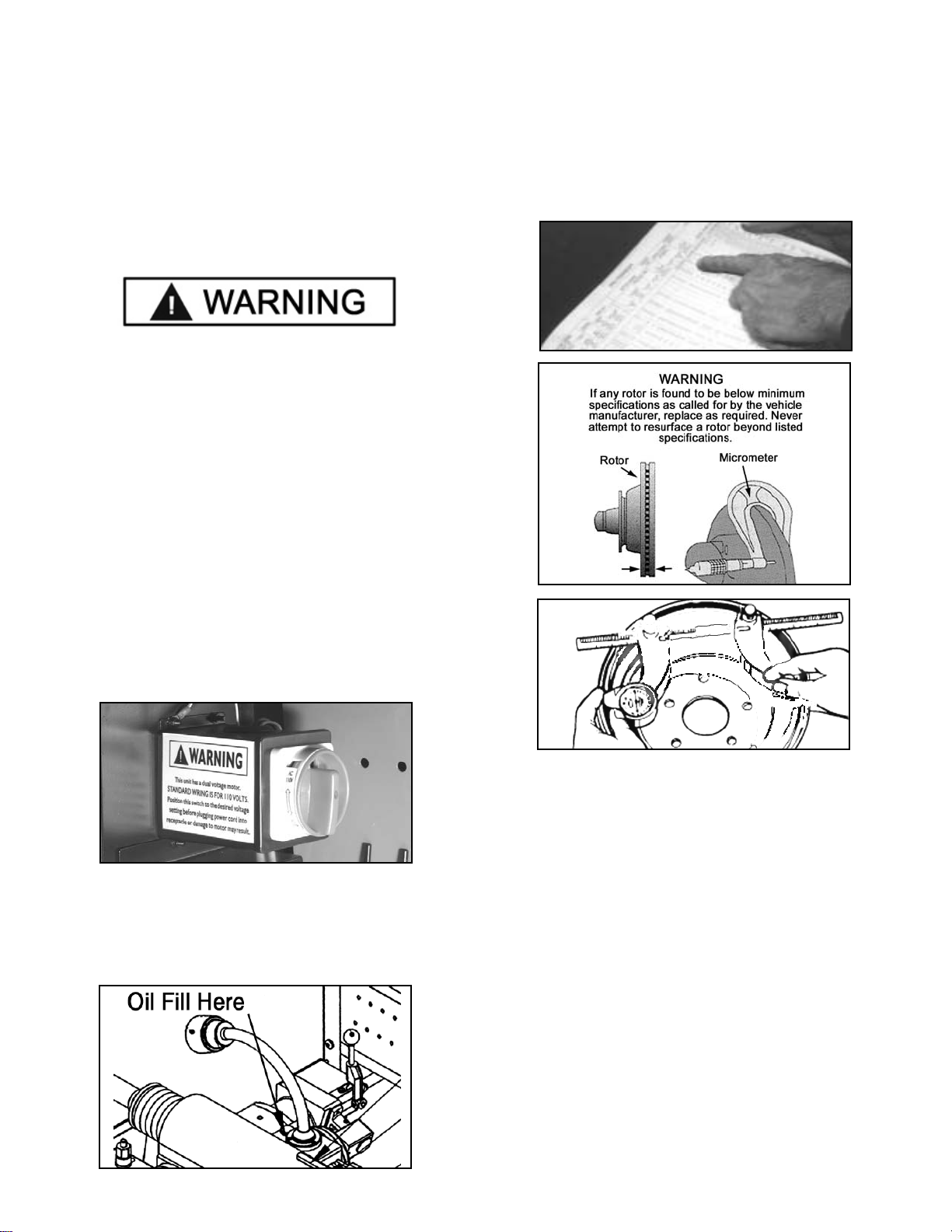
For 220 volt operation it will be necessary to replace the
110 volt 3-prong plug with an appropriate 220 volt 3-prong
plug with ground. After changing the plug, position the
voltage selector switch at the rear of the unit to the 220
setting. Verify that the lathe plug and grounding-type
receptacle match.
4

IMPORTANT NOTICE
Do not attempt to operate this equipment if you have never been trained on basic brake lathe operation procedures.
Stay clear of moving parts that can cause injury. These instructions must be followed to insure proper installation and
operation. Failure to comply with these instructions can result in serious bodily harm and void product warranty.
Manufacturer will assume no liability for loss or damage of any kind, expressed or implied resulting from improper
installation, operation or use of this product.
PLEASE READ ENTIRE MANUAL PRIOR TO INSTALLATION.
5
IMPORTANT SAFETY INSTRUCTIONS
Before operating the lathe, review the warning information on the lathe and the cautions, warnings and dangers
in this manual. Also review the following general safety instructions.
When using your brake lathe basic safety precautions
should always be followed, including the following:
KEEP GUARDS IN PLACE and in working order.
KEEP HANDS clear of moving parts at all times. Keep
hair, loose clothing, neckties, shop rags, jewelry, fingers,
and all parts of body away from moving parts.
ALWAYS USE SAFETY GLASSES. Everyday eyeglass-
es only have impact resistant lenses, they are NOT safety
glasses. Safety glasses, goggles, or a face shield will help pro-
tect the operator from injury. Use a face shield and dust mask
during all operations.
SECURE WORK properly for setup and tool bit
positioning before attempting to make first cut. Do not
attempt to touch rotors or drums with your hands with the
lathe in operation.
REMOVE ADJUSTING KEYS AND WRENCHES
from the lathe before turning it on.
MAINTAIN TOOLS WITH CARE. Keep tools sharp
and clean for best and safest performance. Follow
instructions for lubricating and changing accessories.
USE FACTORY APPROVED TOOLS ONLY. Don’t
force a tool or an attachment to do a job for which it was
not designed. The use of improper accessories may
cause risk of injury to operator or bystanders. Use only as
described in this manual. Use only manufacturer’s
recommended attachments.
KEEP WORK AREA CLEAN and well lighted.
Cluttered areas and benches invite accidents.
LOCATE POWER CORD SAFELY. Do not let power
cord come in contact with moving parts.
REDUCE RISK OF FIRE. Do not operate equipment in
near open containers of flammable liquids and their vapors.
PROVIDE ADEQUATE VENTILATION when working
on operating internal combustion engines. Vehicle
exhaust must be vented from work area.
DRESS PROPERLY. Keep hair, loose clothing,
neckties, shop rags, jewelry, fingers, and all parts of body
away from moving parts. Non-slip footwear is
recommended.
ALWAYS UNPLUG EQUIPMENT from electrical
outlet when not in use. Never use the cord to pull the plug
from the outlet. Grasp plug firmly and pull to disconnect.
DO NOT TOUCH HOT PARTS. Care must be taken
as burns can occur from touching hot parts.
PROPERLY MAINTAIN EQUIPMENT. Do not operate
equipment with a damaged cord or if the equipment has
been dropped or damaged—until it has been examined
by a qualified serviceman.
REDUCE RISK OF SHOCK. Do not use on wet
surfaces or expose to rain.
KEEP CHILDREN/UNAUTHORIZED PERSONS
AWAY. All bystanders should be kept completely away
from the work area.
REMOVE POWER AND DISCONNECT TOOLS
before servicing the unit and when changing accessories
such as blades, bits, cutters, etc. Follow lock-out and
tag-out procedures as required.
AVOID UNINTENTIONAL STARTING. Make sure the
switch is in the OFF position before plugging the machine
in or performing any maintenance or service work.
NEVER LEAN OR STAND ON THE LATHE. Serious
injury could occur if the lathe is tipped over or if the cut-
ting tool is unintentionally contacted.

6
MODEL RL4500
COMBINATION BRAKE LATHE
The Ranger RL4500 Combination Brake Lathe is intended
to resurface disc brake rotors and drums on passenger
cars, medium duty trucks only. Using this lathe for other
purposes could result in personal injury and/or equipment
damage.
FEATURES:
Produces an accurate machined surface that exceeds
OEM specifications.
Simultaneously machines both sides of the rotor
parallel eliminating run-out problems. Rigid mounting
micrometer type tool holders eliminate flexing for maximum
accuracy.
Specially designed adapters assure that rotors are
machined to exceed manufacturer's specifications.
Features twin cutter tool head with micrometer dials and
quick drum-to-rotor changeover. Adjustable spindle speeds
allow for fast rough cut or slow finish cut settings. An
infinitely adjustable spindle-feed gear box provides variable
speed setting.
Supports drums or rotors up to 100 lbs. using the
standard one inch arbor.
Allows you to work quickly and efficiently. Simple design
and ergonomic controls are designed for minimal operator
movement.
A precision lathe that willcut rotors and drums to very
precise tolerances. Durable construction and heavy design
means superior accuracy year after year. Forged, hardened
and ground components resist grooving and premature
wear. Oversize tapered spindles offer superior weight sup-
port
during rotation and a screw-feed oil delivery system
supplies a constant flow of oil to the bearings.
High-impact storage case for tools and accessories.
STANDARD EQUIPMENT INCLUDES
Combination Brake Lathe With Standard Bench
Micrometer-Type Twin Tool Holder / Head
Boring Bar
Carbide Cutting Tools
6-Sided Carbide Cutting Inserts
1" Arbor
Spring
Arbor Nut
Spare Bulb For Lamp
Inside Floating Adapters
Self-Aligning Spacer
Outside Floating Adapter
Centering Cones
Spacers
Double Taper Adapters
Hubless Adapters
Anti-Vibration Bands
Wrenches
Spare Drive Belt
High-impact storage case
Illustrated Instruction Manual
High-Impact Plastic Storage Box And Carrying Case
SPECIFICATIONS
Overall Height - Lathe Alone 17” / 432 mm.
Overall Height - Lathe With Bench: 59” / 1499 mm.
Overall Width - Lathe Alone 45” / 1143 mm.
Overall Width - Lathe With Bench: 48” / 1219 mm.
Overall Depth - Lathe Alone: 35” / 889 mm.
Overall Depth - Lathe With Bench: 35” / 889 mm.
Spindle To Floor - On Bench: 38” / 965 mm.
Electrical: 115/230 VAC, 50/60 Hz, 1-Phase, 20 Amps
Spindle Motor: 1 HP, 115/230 VAC, 50/60 Hz.
Spindle Travel: 6-7/8” / 175 mm.
Spindle Speed - Min: 100 RPM
Spindle Speed - Max: 200 RPM
Spindle Feed Variable: - Min: 0.002 Inch Per Rev. / 0.05 Mm/Rev.
SpindleFeedVariable:-Max: 0.020InchPerRev./0.50Mm/Rev.
Cross Feed - Manual Fine: 0.002 Inch Per Rev. / 0.05 Mm/Rev.
CrossFeed-ManualCourse: 0.01InchPerRev./0.0250Mm/Rev.
Handwheel Tool Feed Graduations: 0.002” / 0.050 mm.
Maximum Rotor Diameter: 14-1/2” / 386 mm.
Maximum Rotor Thickness: 1-7/8” / 48 mm.
Minimum Drum Diameter - Min: 6” / 152 mm.
Brake Drum Diameter - Max: 28” / 711 mm.
Maximum Drum Depth: 6-7/8” / 175 mm.
Maximum Load: 100 Lbs. / 45.36 Kg.
Shipping Weight - Complete: 590 lbs. / 268 kg.

7

INSTALLATION
1. Assemble the bench and chip trays according to the
diagram on page 7. Tighten all fasteners securely.
2.After assembly, the bench should be leveled. The bench
may be bolted down with 3/8” concrete bolts or lag screws.
3. Unbolt the lathe from the shipping pallet and remove
any packing materials and protective wrapping. Lift the
lathe onto the bench.
Always follow safe lifting practices when lifting heavy loads.
Use a forklift or crane only. Do not attempt to lift lathe unit
onto the bench without the use of material handling
equipment with a lifting capacity 400 pounds or greater.
4. Bolt the lathe to the bench with the hardware provided.
Tighten fasteners securely.
5. Remove any packing materials and protective wrapping
from the lathe and components.
6. Make sure the lathe is turned off. Plug lathe into a properly
installed and grounded outlet that matches the lathe plug.
IMPORTANT NOTE
Position the voltage selector switch at the rear of the unit to
the appropriate voltage setting before plugging the lathe into
outlet. Verify that the lathe plug and grounding-type
receptacle match.
7. Remove the oil plug, insert the oil dipstick, and check oil
level. The lathe is shipped with the correct amount and
type of oil. Add oil as necessary to reach the correct mark
on the dipstick. Use only EP-80-90 gear oil. Oil level
should be checked often.
BRAKE ROTOR/DRUM INSPECTION
1. Before attempting any resurfacing, rotor and/or drum
inspection is necessary. Determine the manufacturer's
specifications from an approved specification guide.
2. Using a digital micrometer or other measuring tool, record
the thickness of the rotor or drum. Observe any deep scores
and gouges. This depth will also need to be recorded.
3. Determine if the total amount of material to be removed
will meet the manufacturer's minimum specifications. If any
rotor is found to be below minimum specifications as called
for by the vehicle manufacturer, replace as required.
BASIC OPERATION
To help you understand drum and rotor turning, read the
following that helps explain the features, operation and
principles of drum and rotor resurfacing.
Horizontal Spindle / Arbor
The spindle (horizontal main shaft) is motor driven and
turns the arbor (main rod with threaded tip) which the brake
drums or rotors are mounted on. When turning the drum or
rotor via the arbor and holding a cutting tool against the
braking surface, metal can be removed making the final
result a smooth finish that meets original factory
specifications. Smooth brake surfaces will extend the life of
the brake pads and increase brake operation efficiency.
8

Horizontal Spindle / Arbor Feed
By engaging the spindle feed clutch handle, the spindle
and arbor will move the mounted brake drum to the left.
This feeds the drum braking surface across the cutting
tool (boring bar) as the drum moves away. Spindle feed
may also be done manually without engaging the spindle
feed clutch handle by using the spindle feed hand wheel.
Spindle feed rate refers to the distance the spindle is
moved for each revolution. This speed is variable and can
be adjusted using the spindle variable speed dial.
IMPORTANT NOTE
Spindle feed must be adjusted with the lathe running.
Do not try to move any feed levers or dials without the
drive motor running. Damage may occur to the gears.
Spindle Speed
Spindle speed is adjustable by changing the position of
the V-belt pulley on the rear of the lathe. See page 17.
Cross Feed
The cross feed (forward and aft) draws the tool bit ( micro-
dial twin cutters or boring bar ) across the face of a brake
rotor or flywheel when the cross feed speed setting handle
is engaged.
The cross feed may also be operated manually without
engaging the feed handle using the cross feed hand wheel.
RECONDITIONING BRAKE DRUMS
1. After the following instructions are read and understood,
obtain a scrap drum for practice. First determine if the drum
will be within factory recommended limits after resurfacing is
performed. The DISCARD diameter is often cast or stamped
into brake drums, not the maximum machining diameter.
2. Inspect the brake drum. Do not attempt to machine a drum
that is damaged, excessively worn or in poor condition.
3. Install the boring bar tool holder and boring bar as shown.
9

4. Be sure that a proper tool bit is secure in the boring bar
and the cutting tip is not excessively worn. Sharp cutting
tips must be used at all times. A dull cutter will affect the
finish of both drums and rotors. If the cutting edge is
damaged, replace it promptly. Be sure no metal chips are
under tip when changing tips.
5. Mount the drum on the arbor using the proper adapters,
cones, and spacers.
Mounting Hubbed Brake Drums
Tapered centering cones or double taper adapters fit in the
bearing seats. Be sure to make contact as close as possible to
the middle of the bearing race as possible. Various adapters
and/or spacers may be used to fill out the shaft of the arbor.
Mounting Hubless Brake Drums
Select the largest hubless adapter possible that will fit inside
the drum against the flat lug hole surface. Be sure to
straddle the bolt holes to avoid mounting against a burr, or
remove the burrs with a grinding stone before mounting.
Slip the hubless adapter onto the arbor followed by a spring,
centering cone, the drum, and another similar size hubless
adapter. The centering cone will fit into the center hole of the
drum from the inside to center the drum on the arbor. Fill out
the remaining shaft with various adapters and/or spacers
as needed.
IMPORTANT NOTE
The arbor nut has REVERSE THREADS. Tighten by
turning the arbor nut COUNTER-CLOCKWISE.
IMPORTANT NOTE
The self-aligning spacer should always be used next to
the arbor nut when tightening. To avoid overtightening,
wrench turn the arbor nut counterclockwise until the
drum and adapters become fixed snug on the arbor and
so that you are unable to freely turn them. Then continue
to advance the wrench 1/4 of a turn only. DO NOT
overtighten the arbor nut.
Handle Adapters With Care
The adapters, arbor, and spindle are made
of top grade steel, hardened, and precision ground to
close tolerances. Great care should be taken in their use,
handling, and storage. The smallest nick or scratch can
cause incorrect drum or rotor alignment resulting in
inaccurate resurfacing.
6. Wrap a drum silencing band snugly around the drum.
Be sure it is positioned towards the right-hand edge or
nearest the open side of the drum. IMPORTANT - Failure
to use a silencing band will cause premature wear of tool
cutters and result in a poor finish cut.
10

7. Using the cross feed hand wheel, move the cross feed
to its innermost position by turning the hand wheel
clockwise.
8. Using the spindle feed hand wheel, move the spindle to
its innermost (right hand) position by turning the hand
wheel clockwise and then back off by turning dial wheel
five turns counterclockwise. NOTE: If the hand wheel does
not turn freely, check to make sure the spindle lock and
travel control lock knobs are loosened.
9. Next, position the boring bar by loosening the tool holder
nut and sliding the boring bar towards the innermost side of
the drum, within 1/4” away from the braking surface.
IMPORTANT NOTE
The boring bar position will have to be changed
whenever a drum of different diameter is machined. The
entire boring bar tool holder may be swiveled to achieve
the best cutting position.
10. Check all clearances closely to make sure that nothing
will “crash” when the power is turned on and the drum
starts rotating. NOTE: It may help to turn the arbor nut
counter-clockwise and manually turn the drum by hand to
pre-check all clearances.
Before turning the power on, make sure the cross feed
speed setting handle and the spindle feed clutch handle
are in their neutral positions.
11. Turn the power on.
12. Turn the cross feed hand wheel counterclockwise and
bring the boring bar cutting tip into the braking surface
until it just barely contacts the drum surface and makes a
slight scratch cut.
KEEP HANDS clear of moving parts at all times. Keep
hair, loose clothing, neckties, shop rags, jewelry, fingers,
and all parts of body away from moving parts.
Always wear safety glasses or a face shield. Cutting an
exposed surface such as a brake drum or rotor will
produce flying chips and debris.
11

IMPORTANT NOTE
If the hand wheel does not turn freely, check to make
sure the cross feed lock knob is loosened.
13. Examine the scratch cut making sure it is uniform
around the entire circumference of the drum. If the scratch
cut appears to be deeper on one side of the drum and not
a uniform depth, then turn the power off, remove the drum
from the arbor, check the mounting adapters and arbor for
nicks, burrs, or chips, then remount the drum, and repeat
steps 4 - 13 until a uniform scratch cut is achieved.
14. Holding the cross feed hand wheel firmly in position with
your left hand, carefully rotate the cross feed dial indicator
(the outer, knurled knob) with your right hand until ZERO is
positioned at top dead center and lined up with the tick mark.
This will give you an initial zero-set starting point.
15. Turn the spindle feed hand wheel clockwise until the
boring bar reaches the innermost part of the drum. Be
careful not to crash the boring bar and cutting tip on the
inside wall of the drum or damage to tooling may result.
16. There are 100 graduations on the dial indicator. Each
tick mark represents 0.002” ( 0.05 mm metric ).
GUIDELINES TO DETERMINE THE DEPTH-OF-CUT
• Rough cuts should be no deeper than 0.020”.
• Finish cuts should be no shallower than 0.004” deep.
17. With the lathe running, turn the cross feed hand wheel
dial counterclockwise to the depth desired and then lock
the cross feed by tightening the lock knob.
18. Set the automatic feed shut-off by sliding the travel control
lock knob on the limit rod to a point that approximately equals
the depth of the drum and tighten the knob in place. The limit
rod will then automatically disengage the clutch handle and
stop the spindle feed when it reaches this point.
19. Double check to make sure the spindle lock knob is
loosened then engage the spindle feed clutch handle (move
to the left) to begin auto-feed drum resurfacing. To make sure
the clutch gear is fully engaged, hold the clutch handle to the
left until the spindle feed handwheel starts turning.
By engaging the spindle feed clutch handle, the spindle and
arbor will move the mounted brake drum to the left. The
spindle feed rate can be adjusted by using the spindle
variable speed dial. Adjust the feed rate depending on the
surface finish you desire. Fast for rough cuts and slower for
finish cuts. REMEMBER! Spindle feed must be adjusted
with the lathe running only.Do not try to adjust speed dial
without the drive motor running or gear damage will occur.
20. After the first cut is made, repeat steps 14 - 19 until a
smooth finish cut is made.
12

RECONDITIONING BRAKE ROTORS
After the following instructions are read and understood,
obtain a scrap rotor for practice. Inspect all rotors
carefully for excessive scoring, rust ridges (at the inner
and outer circumference of the rotor), and blemished hard
spots.Any excessive wear or deformity should be noted. If
the rotor is not within acceptable limits, the rotor should be
replaced.
Always use a micrometer to check the thickness of the
rotor. If the rotor thickness is less than the minimum
established by the manufacturer, or if it will be less after
reconditioning, the rotor should be replaced.
Twin Cutters
A micro-dial twin cutter tool assembly is used to
recondition both surfaces of a brake rotor at the same
time. The twin cutter replaces the boring bar on top of
the cross feed after removing the boring bar and tool
holder boring bar brackets.
Practice setting the micro-dial cutters for machining rotors.
Learn all the functions thoroughly to insure proper
operation. Most rotors will have the minimum thickness
values cast into the outer surface.
The proper procedure for determining whether to
resurface rotors or discard them is as follows:
A. Using a micrometer or some other micrometer suitable
for measuring the thickness of the rotor to be machined,
check the rotor thickness at four points (90 degrees apart)
about 1" from the outer diameter.
B. If the thickness at any of the four points is less than the
minimum established by car manufacturers as shown on
the rotor or in a current brake specifications book, replace
the rotor.
C. The rotor may be resurfaced if scored or it has a small
amount of runout, provided it is within the minimum
thickness requirement.
D. After the rotor is machined, measure the thickness
again, and, if it is not within the allowable minimum limits,
discard it. NOTE: This check requires a measurement in
only one spot if both braking surfaces cleaned up 100%,
because the turning operation assures almost absolute
parallelism.
Preparing For Twin Cutters
1. Remove the boring bar and tool holder brackets.
2. Using the spindle feed hand wheel, move the spindle to
its innermost (right hand) position by turning the hand
wheel clockwise and then back off by turning dial wheel
three turns counterclockwise. On some deeper rotors it
may be necessary to move the spindle farther left. For
best results, always position the spindle as far to the right
as the job will allow. NOTE: If the hand wheel does not
turn freely, check to make sure the spindle lock and trav-
el control lock knobs are loosened.
3. Turn the cross feed hand wheel counterclockwise and
move the cross feed assembly away from the arbor. This
will make room for the twin cutters after the rotor is
installed. If the hand wheel does not turn freely, check to
make sure the cross feed lock knob is loosened.
IMPORTANT NOTE
If the cross feed assembly moves too far outward the
feed screw may exit the feed screw nut and cause the
cross feed assembly to become disengaged from the
hand wheel. If this happens, simply push firmly forward
on the RIGHT SIDE of the cross feed assembly while at
the same time turning the cross feed hand wheel
clockwise until the feed screw engages the feed screw
nut and the cross feed assembly begins to move.
Mounting Brake Rotors
4. Clean excess grease from bearing races of rotor. Inspect
bearing races for damage and replace if necessary.
5. With the power turned off, mount the rotor on the arbor
using the proper adapters, cones, and spacers.
Hubbed Brake Rotors
Tapered centering cones or double taper adapters fit in the
bearing seats. Be sure to make contact near the middle of
the bearing race whenever possible rather than near an
edge. Various adapters and/or spacers may be used to fill
out the shaft of the arbor.
13

Hubless Brake Rotors
Select a hubless adapter which will fit inside the drum
against the flat surface. Be sure to remove any burrs with
sandpaper or wire brush. Slip the hubless adapter onto the
arbor followed by a spring, centering cone, the drum, and
another hubless adapter. Fill out the remaining shaft with
various adapters and/or spacers as needed.
6. With the power turned off, mount the micro-dial twin
cutter assembly on the tool holder stud bolt extending the
bolt through the cast slot. The slot of the twin cutter should
be approximately parallel to the lathe spindle and the center
of the twin cutters lined up with the centerline of the rotor.
NOTE: It helps to use the safety shield mounting bolt as a
guide to line up twin cutters with the centerline of rotor.
7. Secure the twin cutter to the tool holder with the self
aligning nut and washer assembly. Tighten the nut firmly.
8. Install the safety shield if it was removed for storage
then review the cautions and dangers section and the
general safety information at the beginning of this
manual. The safety shield is easily screwed onto the twin
cutter in the threaded mounting hole provided.
IMPORTANT NOTE:
Do not overtighten arbor nut when mounting rotors on
the spindle. The pressure of one hand on the wrench is
sufficient to tighten. If centering cones, adapters and
spacers are not clean and free of nicks and burrs or
foreign matter when the arbor is tightened, it could
introduce spindle runout or “wobble”.
9. With the power turned off, install a silencer band that is
appropriate for the rotor being machined. Stretch the band
around the rotor and hook the metal loop over a lead weight.
10. Adjust both micrometer tool-feed knobs on the tool
holders making sure the cutting bits are opened wider than
the width of the rotor.
11.Turn the cross feed hand wheel clockwise and
manually feed the cutting tools inward stopping near the
center of the rotor. Remember, the hand wheel will not turn
manually unless the cross feed lock knob is loosened.
14

12. Check all clearances closely to make sure that nothing
will “crash” when the power is turned on and the rotor starts
rotating. NOTE: It may help to loosen the arbor nut slightly
and manually turn the rotor by hand to check all clearances.
13. Adjust the drive belt to match the rotor size.The speed of
the spindle is adjustable by changing the position of the V-belt
pulley at the rear of the lathe. See page 17 for adjustment pro-
cedure. Use the outer pulley groove (FASTEST SPINDLE
SPEED) for passenger car and most light duty truck rotors.
Choose one of the inner pulley grooves (SLOWER SPINDLE
SPEEDS) when machining medium duty and larger truck
rotors and some solid rotors.
13. Before turning the power on, make sure both speed
setting handles are in their neutral positions.
14. Turn the lathe ON.
15. Turn each tool bit control (the outer knurled knobs)
clockwise until the tool bits just barely contact the rotor
surfaces and makes a slight scratch cut. NOTE: The dial
locks for the micro-dials must be loosened before
adjustments are made. After required adjustments are
made, re-tighten dial locks to hold cutting tips secure.
KEEP HANDS clear of moving parts at all times. Keep
hair, loose clothing, neckties, shop rags, jewelry, fingers,
and all parts of body away from moving parts.
Always wear safety glasses or a face shield. Cutting an
exposed surface such as a brake drum or rotor will
produce flying chips and debris.
16. Examine the scratch cut making sure it is uniform around
the entire circumference of the rotor. If the scratch cut
appears to be deeper on one side of the rotor and not a
uniform depth, then turn the power off, remove the rotor from
the arbor, check the mounting adapters and arbor for nicks,
burrs, or chips, remount the rotor, and repeat the process.
17. Check to make sure the spindle lock knob and
micro-dial lock knobs are tightened before continuing.
18. Hold the outer knurled knobs firmly with your left hand,
then carefully rotate the inner knurled dial indicator knobs
clockwise with your right hand until ZERO is positioned at
top dead center and lined up with the tick mark. This will give
you an initial zero-set starting point.
15

19. Manually turn the cross feed hand wheel
counterclockwise and move the cutting tools outward
toward the edge of the rotor to remove any rust build-up or
high areas on the outer edge.
20. After cleaning up the outer edge of the rotor manually
feed the cutting tools inward towards the center of the rotor
to a point slightly beyond the contact surface of the brake
pads being careful not to run the carbide inserts into the
hub portion of the rotor.
21.Turn both tool bit controls (OUTER KNURLED
KNOBS) to the desired depth-of cut then lock them in
position by tightening the dial lock knobs.
USE THESE GENERAL GUIDELINES
TO DETERMINE THE DEPTH-OF-CUT
Either rough or finish cuts may be taken to resurface a
rotor. Generally, finish cuts should be 0.004” (0.10 mm)
to 0.006” (0.15 mm) per side. Very shallow cuts of less
than 0.004” (10 mm) per side tend to reduce tool bit life
because the heat generated during reconditioning isn’t
transferred to the rotor efficiently. Rough cuts may be
taken from 0.006” to 0.010” per side.
IMPORTANT NOTE
Hold OUTER knobs with one hand and turn CLOCK-
WISE to move cutting tips inward towards rotor. There
are 10 large graduations on each dial indicator. Each mark
represents 0.002” english ( 0.05 mm metric ).
22. Engage the automatic cross feed to begin the cut by
moving the lever to the desired speed. The cross feed will
stop automatically when the cutting tools have moved all
the way across the face of the rotor.
IMPORTANT NOTE
For roughing cuts, move the cross feed lever to the
FAST position. Rough cuts may be taken from 0.006” to
0.010” per side.
23. Manually feed the cutting tools inward towards the
center of the rotor to a point slightly beyond the contact
surface of the brake pads being careful not to run the
carbide inserts into the hub portion of the rotor.
24. Turn the end knob of each tool bar micro-dial
individually to set each tool bit to the desired depth-of cut.
Remove only enough material to clean up each side.
25. Engage the automatic cross feed to begin another cut.
26. When the tool bits have cleared the rotor, disengage
the cross feed and turn the lathe OFF.
27. Inspect the brake surfaces. If part of the surface was
not cut, leave the tool bars locked in position, turn the
lathe ON, slowly turn the cross feed handwheel clockwise
until the outer tool reaches the groove at the rotor hub,
and repeat steps 20 -23.
28. Repeat steps until a smooth finish cut is made.
16

RECONDITIONING FLYWHEELS
Mounting Flywheels
1. Clean the machined surfaces, so they are free of rust,
dirt and burrs.
2. Mount the flywheel in the same manner as a hubless
rotor or drum, with the side to be machined facing the
lathe.
IMPORTANT NOTE
Dowel pins or studs must be removed before machining
can be performed. Use silencers when possible. Magnet
packs or bars may be used as silencers.
Machining Flywheels
5. Install the boring bar tool holder and boring bar as shown.
6. Loosen the two square head set screws on the boring
bar holder and replace the tool bits with the reverse end
tool cutter.
7. The left hand edge of the tool bit insert should be as
close to 90 degree to the surface to be machined as
possible. Adjust (swivel) the boring bar to obtain the most
optimum angle for cutting.
8. Proceed with steps 15-28 (cutting rotors) shown on
pages 15-16.
When machining cup-type flywheels you must stay with
the lathe, because you must stop the unit and reposition
the tool bar for the outside lip surface. You must also
remove the same amount from the outside mounting
surface as was removed from the lower surface; failure
to do this may cause incorrect clutch operation.
ADJUSTING SPINDLE SPEED
The RL4500 brake lathe has three spindle speed pulley
settings in addition to an infinitely variable spindle feed
dial to accommodate a wide range of machining tasks. It
is important to remember that the desired surface finish
depends on the correct relationship of the spindle speed
with the cross feed speed. As a general rule, slower
spindle speeds require slower cross feed speeds. Also
deeper cuts normally dictate that a slower cross feed rate
and/or spindle speed may be necessary.
Multi-Speed Settings
The RL4500 brake lathe has three different pulley
selections.
(1) The small outside pulley at the motor in conjunction
with the large pulley at the gear box drives the spindle at
70 -98 RPM's. This speed is recommended for large
diameter drums, rotors, and most flywheels; the cross
feed rate should be set at a slow setting.
(2) The middle pulleys rotate the spindle at 88 -123 RPM's
and are normally used to machine intermediate size rotors
and drums that have a diameter larger than that used on
most passenger cars.At this spindle RPM, cross feed can
be set at a slow and fast feed rate.
(3) The large pulley at the motor and the small pulley at
the gear box allows the spindle to rotate at 118 - 165
RPM's. This spindle speed should be satisfactory for most
passenger car drums and rotors. The cross feed speed
may be set at a variety of rates from slow to fast to
produce the desired finish.
Spindle Speed Adjustment
This V-belt adjustment must be made with the lathe off.
1. Release the belt tension by moving the V-belt
adjusting lever to the right (clockwise).
2. Open the rear pulley cover to access the v-belt pulleys.
3. Move the belt to the pulley groove that will give the
correct spindle speed for the cut to be taken.
4. Reapply tension to the V-belt by moving the adjusting
lever back to the operating position.
17

INSTALLATION INSTRUCTIONS
Location
Select a location that will provide the operator with enough
space to use the equipment in a safe manner. The area
selected should be well lit, easy to clean and should be
away from oil, grease, etc. Avoid areas where bystanders
and customers may be present.
Electrical Source
This unit requires power from a 15 amp electrical circuit.
Refer to the serial tag of the machine for specific electrical
requirements. Have a licensed electrical technician perform
any necessary changes to the power source before plugging
in the unit. The electrical source must have a solid
connection between ground and building ground.
MAINTENANCE INSTRUCTIONS
Read and follow all the maintenance instructions provided
in this manual to keep the lathe in good operating
condition. Regular inspections and proper maintenance
are essential to preventing accidents and injuries. These
instructions will help you service the unit. Instructions are
for a person with some mechanical ability and training. No
attempt has been made to describe all basic steps like
how to loosen or tighten fasteners. Basic procedures such
as cycling systems and checking operation of the equip-
ment are not fully described since they are described in
this manual. Do not attempt to perform work beyond your
ability or at which you have no experience. If you need
assistance, call an authorized service center or contact
the factory.
PREVENTIVE MAINTENANCE
Check for worn, damaged or missing parts including
grips and protective covers. Replace them before allowing
the unit to be used.
Make sure all fasteners are securely tightened and all
guards and covers are in place.
Replace any damaged or missing safety decal’s. They
are available from the factory.
On a daily basis, inspect the unit and check to be
certain that all systems are operating normally. Follow
detailed inspection and testing procedures for various
components at regular intervals.
GENERAL LUBRICATION
Oil the ways of the head assembly and thread screw
periodically with a light oil. Note: Cross feed should be in
full inward position during lubrication.
Oil the threaded rods periodically with a light oil. Spray
the drum lead screw with silicone lubricant.
Lightly oil the dovetails with motor oil.
CLEANING
Keep the lathe as clean as possible for trouble free
operation as well as safety and longer lathe life. Use a
brush to sweep metal chips and dust off the lathe.
After use, always wipe clean.
Clean all exposed metal parts with a brush and apply
a light coating of motor oil with. Note: DO NOT apply oil to
the tool slide clamping surface or the round tool holders on
the twin cutter.
Use only Ranger original or authorized service
parts to insure safety and performance.
18
Before making any inspection, adjustment, or
repair, disconnect the power source and block out all
moving parts to prevent injury.
Keep the machine and the immediate work area
clean. Do not use compressed air to remove dirt and
debris from the lathe. Chips and dust may be driven
between machined parts and into bearings causing
undue wear and foreign material may be propelled
into the air and into operator or bystander causing
personal injury.
Wear protective clothing and use eye protection
when making any adjustments or repairs to the
machine.
Proper unit installation is necessary for safe use
and efficient operation. Proper installation also
helps protect the unit from damage and makes
service easier. Always keep this manual nearby.

19

20
Table of contents
Other Ranger Products Lathe manuals
Popular Lathe manuals by other brands

MetalMaster
MetalMaster PB-170B instruction manual

Scheppach
Scheppach DM600VARIO Translation of original instruction manual

GÜDE
GÜDE GDM 450 instructions

HENNESSY INDUSTRIES
HENNESSY INDUSTRIES Ammco 800 Safety Instructions, Installation Instructions, Operating Instructions, Maintenance Instructions

Rikon Power Tools
Rikon Power Tools 70-100 Operator's manual

Haas
Haas ST-10/30 troubleshooting guide

Clarke
Clarke CWL1000B Operation & maintenance instructions

Shop fox
Shop fox SHOP FOX M1016 Specifications

Jet
Jet Elite 1700 Series Operating instructions and parts manual

Grizzly
Grizzly G0776 owner's manual

Hoffmann
Hoffmann X-18 Operating and maintenance manual

Delta
Delta 434-08-651-0001 instruction manual