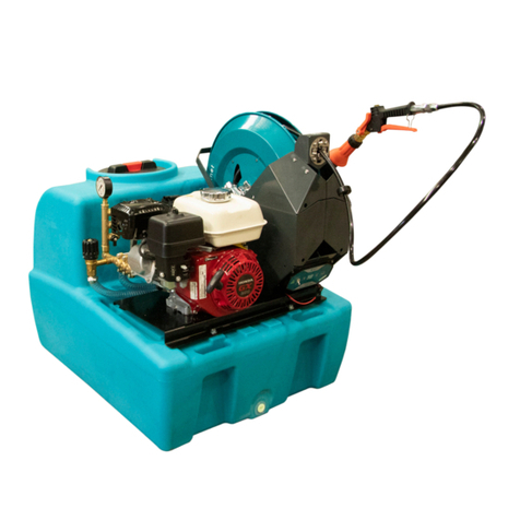
Rapid Spray FIELDLINK ECO Service manual

FIELDLINK
OPERATORS HANDBOOK
FIELDLINK ECO
FIELDLINK PRO
400L / 600L / 800L

Rapid Spray FieldLink Operators Handbook
Rapid Spray Equipment by Rapid Spray
CONTENTS
01 Introduction
02 Warnings
03 Product Risk Assessment
03 Troubleshooting
05 Unit Assembly
06 Mounting Hose & Gun Holder
07 Mounting Controls
08 Mounting Electric Controls
09 Mounting Boom
10 Mounting Hose Reel - Manual & Buddy Smart Reel
PTO Sha Instructions
11 Warnings
12 Correctly Size PTO Sha
13 Fitting PTO Sha
14 Hitching FieldLink to Tractor
15 Filling & Mixing
16 Calibration
17 Spraying
19 Cleaning & Maintenance
20 FieldLink Breakdown
23 Bertolini Poly 2073 Pump
25 Warranty
27 Warranty Registration

Rapid Spray FieldLink Operators Handbook
Rapid Spray Equipment by Rapid Spray REV OCT 2019
1
INTRODUCTION
Congratulations on your purchase of a Rapid Spray FieldLink 3-Point Linkage Sprayer
which has been designed for eortless spraying of herbicides and pesticides.
The design of the tank enables the unit to be mounted onto tractors of varying sizes from
approximately 35HP and greater.
DISCLAIMER: In line with our policy of continuous improvement, the weights, dimensions and design may change
slightly from what is shown in the book. Rapid Spray accepts no liability for the unsafe operation of this unit.

Rapid Spray FieldLink Operators Handbook
Rapid Spray Equipment by Rapid Spray
2
1. When mounting to any vehicle/tractor, ensure that you have read the Vehicle Owner’s
Manual and that you comply with all the weight restrictions as specified by the vehicle
manufacturer, as overloading can cause injury or death.
2. To ensure your own safety and that of your employees, you must comply with all
relevant environmental and work place health and safety regulations and codes of
practice.
3. Select and wear the appropriate Personal Protection Equipment in accordance with
the label of the product you intend on using and your own safe work practices.
4. Care should be taken when spraying in windy conditions as spray dri may
contaminate the air and may eect the operator or damage adjacent non-target
vegetation.
5. Once the spraying operation has been completed, decontaminate the spray tank and
spray accessories. Dispose of rinsing’s in compliance with current environmental and
work place health and safety regulations.
6. Personal Protection Equipment must still be worn while decontaminating your hose
reel as per warning 3. above.
7. Improper or careless use of this sprayer can cause serious injury. Minors should never
be allowed to use this sprayer. This sprayer should not be used when bystanders or
animals are in the area. This sprayer should never be used while children are in the
area.
8. Never leave the sprayer unattended without turning o the engine and relieving the
line pressure, and flushing the sprayer of any harmful chemicals.
9. You must be in a good mental health to operate this sprayer and not be under the
influence of alcohol or any drugs that could impair your vision, physical strength,
dexterity, judgement or mental capacity.
10. Pump is driven by rotating driveline. Contact can cause serious injury or death. Never
operate without driveline guards.
11. No modifications and/or alterations may be made to this sprayer. Any such
modifications not only void the sprayer warranty but can make the unit dangerous to
anyone operating the pump.
12. Always inspect hoses and piping to avoid burst injuries.
WARNINGS

Rapid Spray FieldLink Operators Handbook
Rapid Spray Equipment by Rapid Spray REV OCT 2019
3
PRODUCT RISK ASSESSMENT
TASK HAZARDS RISK CONTROL MEASURES
1. Partially fill the
tank with water,
connect the PTO
sha - DO NOT
exceed RPM for
the PTO and test
the spray unit.
Reaching & handling;
slips, trips or falls; fingers
jammed; pressure blow;
electrocution; PTO sha
entanglement. NOTE: PTO
and machine must match;
can’t be opened when
operating or the shield is
not safely in place.
Med Concentrate on task; follow safe manual
handling techniques; don’t li > 20kg
if on your own, bend knees and keep
back straight; keep fingers clear; no
loose clothing; follow PTO & machine
safe operation steps; ensure guard on
PTO sha before use; keep unit at least
8m away from overhead powerlines;
fire extinguisher nearby; follow warning
stickers on tanks; check hoses; keep
substances away from electrical sources.
2. Check weather
and select the
appropriate PPE to
suit the chemicals
to be used.
Manual handling; slips,
trips and falls.
Low Put on PPE as per the chemical
requirements in the Material Safety Data
Sheet - coveralls, gloves, safety, footwear,
glasses and respirator; follow safe manual
handling procedures: as above.
3. Mix chemicals
and fill spray tank
units.
As above; spray dri,
chemical spillage,
emission of vapours or
flammability; weather;
untrained visitors.
Med As above; user trained in the state’s
chemical mixing and administration
course e.g. Chem Cert; follow the relevant
Environment Protection Authority
requirements, fire extinguisher present;
keep visitors away from the job unless
wearing full PPE.
4. Use spray unit.
DO NOT exceed
the RPM for the
PTO.
As above; loss of load;
work in heat and cold;
noise; exceed load limit
of vehicle; hose and PTO
sha entanglement on
terrain and slopes; run
over by unit when in use.
High As above; wear clothes to suit heat &
cold; wear hearing protection if pump
noise > 85 dBa; follow manufacturer’s
safe operation instructions for
the vehicle and the spray unit; don’t
overload-water weighs 1kg per 1 litre;
secure load to vehicle; hose tidy; brakes
on when vehicle stopped.
5. Clean up,
maintenance and
storage.
As above; PTO greasing;
fresh water tank use.
Low As above; continue to wear PPE for clean
up, store tank in a dry, well ventilated
area.
Buddy Smart Reel See ‘ Buddy Smart Reel Operators
Handbook’

Rapid Spray FieldLink Operators Handbook
Rapid Spray Equipment by Rapid Spray
4
TROUBLESHOOTING
CONDITION CAUSE REMEDY
Pump will not
prime
1. Insuicient motor RPM
2. Air leak on suction plumbing
3. Blocked/ restricted intake
hose
4. Filter cap disengaged
5. Filter gasket damaged /
missing
1. Increase motor RPM until pump primes
2. Tighten/ replace fittings and hose
clamps. Verify suction hoses are in good
condition.
3. Remove blockage from suction line,
ensure line is not kinked.
4. Lock filter cap into position.
5. Replace filter gasket.
Pressure drops
/ fluctuates
during standard
operation
1. Restriction on suction line
2. Pump sucking air
3. Plugged filter
4. Damaged regulator
1. Inspect tank and suction lines and
remove restriction
2. Tighten fittings
3. Remove and clean filter mesh and
housing
4. Remove regulator stem and inspect for
broken parts / pieces
Pressure gauge
not registering
1. Plugged with debris 1. Unthread, check and clean pressure
gauge
Hand gun loses
pressure
1. Debris in hose or nozzle
2. Pump losing prime
3. Pump pressure dropping /
fluctuating
1. Unthread nozzle tip and clean
2. See ‘Remedy’ for ‘Pump will not prime’
3. See ‘Remedy’ for ‘Pressure drops /
fluctuates during standard operation’
Buddy Smart
Reel
See ‘Buddy Smart Reel’ Operators Handbook
Pump See pump ‘Operator’s Handbook’.

Rapid Spray FieldLink Operators Handbook
Rapid Spray Equipment by Rapid Spray REV OCT 2019
5
UNIT ASSEMBLY
Before using your FieldLink, you may need to assemble a few of the components before
commencing spraying.
If you have any queries or questions further to the instructions on the following pages,
please feel free to give one of our friendly customer service members a call on 1800 011 000,
and they will be happy to guide you through the steps.
NOTES

Rapid Spray FieldLink Operators Handbook
Rapid Spray Equipment by Rapid Spray
6
MOUNTING HOSE & GUN HOLDER
1. Attach Brackets
Attach hose hangers using bolts supplied.
2. Attach Hose Clips
Attach hose clips to front using screws supplied.
Wrap hose around hangers and mount gun.
Item No. Part No. Qty Description
1 CHS10M02546Z 4 M10 Bolt x 20mm
2 CHWF10MHZ 4 M10 Washer
3 CHWS10MS 4 M10 Spring Washer
4 CHLM05M025Z 2 M5 x Pan Phillips Head x 25mm
5 CHWS05MS 2 M5 Washer
6 CHNN05MZ 2 M5 Nylock Nut
7 CHCLP12MMX2 Pack 2 Lance Clips
8 ASFL00600FLHH 2 Hose Hangers
1
2
8
6
5
7
4
3

Rapid Spray FieldLink Operators Handbook
Rapid Spray Equipment by Rapid Spray REV OCT 2019
7
MOUNTING REGULATOR
Item No. Part No. Qty Description
1 ARTA20B14024E3M1 1 Arag Controller (optional)
2 ASFL00600FLRB Set 2 Regulator Mounting Bracket
3 CHS08M02546Z 4 M8 x 25mm Bolt
4 CHWF08MHZ 8 M8 Washer
5 CHNN08MZ 4 M8 Nyloc Nut
6 CHS06M02546Z 4 M6 x 25mm Bolt
7 CHWS06MHZ 4 M6 Spring Washer
8 CHWF06MHZ 4 M6 Washer
1. Attach Mounting Brackets & Regulator
Attach mounting bracket using bolts supplied.
Mount regulator facing forward with bolts as supplied.
2. Attach Hoses
Mount three black hoses in order using pin clips.
Mount clear return hose using large pin clip.
Ensure pressure control is at half way position.
5
4
3
1
8
6
7
2

Rapid Spray FieldLink Operators Handbook
Rapid Spray Equipment by Rapid Spray
8
MOUNTING ELECTRIC CONTROLS
1. Mount Regulator & Hoses
Follow regulator mounting instructions as per
"Mounting Regulator" on page 7.
2. Attach Electrical Cables
Attach control box wires labeled 1 - 3 to each section
valve. Insert screws to hold in place.
NOTE: Do not attach wire labeled P.
3. In-Cab Control Box
Using clips supplied, install/mount control box in the
cab of the tractor for easy reach.

Rapid Spray FieldLink Operators Handbook
Rapid Spray Equipment by Rapid Spray REV OCT 2019
9
MOUNTING BOOM
Item No. Part No. Qty Description
1 ASFL00600FL (component) 2 Slotted Attachment Mount (component)
2 ASFL00600FL 2 Universal Mount Z-Bracket
3 CBO1030ZP 4 M10 x 30mm Cup Head Bolt
4 CHWF10MHZ 20 M10 Washer
5 CHNN10MZ 6 M10 Nyloc Bolt
6 CHS10M03046Z 4 M10 x 30mm Bolt
7 CHNH10M88Z 8 M10 Nut
8 1 Boom
9 CHUS10M050X060 4 M10 U-Bolt
1. Slotted Mounting Attachment
NOTE: Component 1 will be already attached to frame.
Attach universal z-brackets. Loosely fit slide bolts.
2. Mount Boom & Attach Hoses
Slide boom into slotted attachment, set height of boom
and tighten slide bolts.
Attach boom hoses.
3
6
5
21
9
8
2
4
47

Rapid Spray FieldLink Operators Handbook
Rapid Spray Equipment by Rapid Spray
10
MOUNTING HOSE REEL
Item No. Part No. Qty
(Buddy)
Qty
(Manual) Description
1 1 1 Hose Reel
2 ASFL00600FLSB 1 Buddy Mount Plate
3 CHS10M02046Z 4 M10 x 20mm Bolt
4 CHS10M03046Z 4 4 M10 x 30mm Bolt
5 CHWS06MHZ 4 4 M10 Spring Washer
6 CHWF10MHZ 8 4 M10 Washer
1. Attach Mounting Plate and Hose Reel
Using bolts supplied, mount Manual hose reel straight
onto tank. (No mounting plate required).
Attach mounting plate to the FieldLink tank first, then
the Buddy Smart Reel using the bolts supplied.
2. Attach Hoses
Run supplied hose from reel to spare outlet on controls.
Secure hose tail using pin clip and hose using hose
clamp supplied with hose.
6
4
2
3
5
1
4
5
6

Rapid Spray FieldLink Operators Handbook
Rapid Spray Equipment by Rapid Spray REV OCT 2019
11
PTO WARNINGS
When operating a PTO sha, ensure the following:
• Wear tight fitted clothing while connecting and disconnecting your sprayer.
• Shut o tractor and remove the keys before connecting or disconnecting PTO to pump.
• Do not reach over the back of the tractor to adjust the PTO or throttle.
• Never step over a revolving PTO sha even if shielded.
• Do not operate PTO sha without guards, damaged guards or using the restraining
members correctly attached; ensure guards are in place while spraying.
• Do not expose guarded parts of the sha by cutting or enlarging grease access holes.
• PTO shas and safety clutches have to match the power take o and the machine type.
See the instructions with your machine for recommended type and size of sha and
clutches. Overload can cause damage.
• Do not operate above recommended speeds. No device (e.g. adapters) shall be
installed between the tractor PTO and the PTO drive sha. No changes may be made to
the PTO drive sha and it's guard, except in length adjustment.
WARNING: PTO shas are extremely dangerous
and can cause grievous bodily harm or death
if incorrectly used. Follow all manufacturer
instructions and Safe Work procedures when
using PTO driven machinery.
NOTE: Always wear safety gloves when cutting PTO sha. Image for marketing purposes only.

Rapid Spray FieldLink Operators Handbook
Rapid Spray Equipment by Rapid Spray
12
CORRECTLY SIZE PTO SHAFT
STEP-BY-STEP PTO SHAFT CUTTING GUIDE EXAMPLE
1. Aer hitching your FieldLink to your tractor using the 3PL arms, raise it a height where
the PTO sha output on the tractor and the sprayer align horizontally with each
other.
2. Measure INSIDE GROOVES
Measure from the groove which runs around the sha on the
tractor to the same position on the FieldLink and take note of
this measurement.
890mm
3. Remove the safety guards from either end of the PTO sha.
4. Measure NEW SHAFT (mm)
Push the two halves together so that sha is at it's shortest
length and measure from one locking pin to the other; take note
of this measurement .
1194mm
5. The required sha length is the first measurement (from groove to groove) minus
a minimum of 76mm (3") to allow for disconnection from the tractor. If the sha is
already shorter than this, ensure that minimum of 50% of total sha length overlaps
when in operation.
6. Amount to cut o sha:
NEW SHAFT (Step 4.) - INSIDE GROOVES (Step 2.) + 76mm = CUT TOTAL 1194 - 890 + 76 = 380
7. To find the length to cut of each end of sha, divide the CUT TOTAL from
Step. 7 by two. Cut this length o each sha.
CUT TOTAL ÷ 2 = CUT LENGTH
380 ÷ 2 = 190mm
8. Cut the CUT LENGTH of both ends of the sha using a hacksaw or metal saw. Remove burrs
from the inside using a file. Grease both ends of the sha and slide them together to the
shortest length.
9. Cut the same amount o both safety tubes from Step 7. Deburr ends and remove any plastic
shavings. Reinstall sha safety guards to sha ensuring they have locked in place.
Tractor models vary in distance between bottom link arms and the PTO sha output, as
do implements, resulting in a need to adjust the length of your PTO sha to ensure safe
operation prior to the first use.
WARNING: Do not operate the tractor PTO until correct fitting has been checked. Doing so
will damage your pump and tractor.

Rapid Spray FieldLink Operators Handbook
Rapid Spray Equipment by Rapid Spray REV OCT 2019
13
FITTING PTO SHAFT
STEP-BY-STEP PTO SHAFT CUTTING GUIDE
1. Install the PTO sha onto the tractor and FieldLink while sha is horizontal and at it's
shortest length. If you cannot fit the sha at this point as it is too long, it will need to
be shortened further.
2. Without running the PTO, lower the FieldLink to the ground and check the angle of
the sha and universal joints. This angle should not exceed 25° at rest.
3. Raise the FieldLink to the maximum operating height and check the angle of the sha
and universal joints. This angle should not exceed 17° for continuous operations.
4. Lastly, check the overlap of the sha end exceeds 50% of the total length of the sha
operation to prevent premature failure of the sha.
See https://resources.rapidspray.net/blog/how-to-
correctly-size-your-3pl-sha for full guide with images.

Rapid Spray FieldLink Operators Handbook
Rapid Spray Equipment by Rapid Spray
14
HITCHING TO TRACTOR
Once your FieldLink has been fully assembled, it is ready to hitch to your tractor. Follow the
steps below:
1. Align Tractor
Back the tractor up to the FieldLink with the le
and right tractor arms at the same height of the
mounting points on the FieldLink.
2. Insert Pin Arms
Hook each tractor arm onto a mounting point and
secure it with a lock pin.
NOTE: Please refer to tractor operating manual for
3-point locking system instructions.
3. Insert Pin to Top Link
Hook up the top link to the third mounting point at
the centre of the unit and insert the correct sized
lock pin.
4. Connect Pump
Connect the pump to the PTO sha and hook
on the torque chain to keep the PTO sha from
rotating with the pump rotation.
NOTE: See pages 6 - 8 on correctly cutting and
fitting your PTO sha.
WARNING: PTO shas are dangerous. Never work in
the vicinity of a PTO sha while tractor is turned on.
5. Test / Level Fieldlink
Using the tractors hydraulics, li your sprayer o
the ground to ensure it has been secured properly
and is correctly aligned with the rear of the tractor.
Adjust tractor arms accordingly.

Rapid Spray FieldLink Operators Handbook
Rapid Spray Equipment by Rapid Spray REV OCT 2019
15
The following steps are given as a guide to mixing and filling your FieldLink sprayer.
1. Read the product and follow the instructions carefully, taking special note with regard
to the order in which the products are added to the tank.
NOTE: Mixing sites must be well away from watercourses and other environmental sensitive
areas. Children and animals must be kept away.
2. Measure out the correct quantity of pesticides using clean measuring jugs used only for
this purpose.
3. Half fill the sprayer with clean water.
4. Commence agitation of FieldLink with following steps:
• Pressure control lever must be in the ‘by-pass’ position. Turn regulator valve knob
in an anti-clockwise direction to reduce pressure to ‘O’ bar.
• Engage PTO sha to commence pumping and fluid circulation. Now add the
pesticides as measured correctly before to the spray tank while still agitating.
• Rinse out the measuring jug and pour all rinsing’s into the spray tank. Safely
dispose of empty containers in compliance with current regulations.
• Top up the tank with water to the required level; ensure that the tank is not over-
filled and the outside is clean and dry before handling.
• Your Fieldlink has now been correctly filled and the product thoroughly mixed.
Spraying can now commence.
5. To commence spraying, move the pressure control lever clockwise to the ‘press’
position, close the spray gun or boom and turn the adjustment knob in an anti-
clockwise direction until your desired pressure has been reached. Open the spray gun
or boom and start spraying.
FILLING & MIXING

Rapid Spray FieldLink Operators Handbook
Rapid Spray Equipment by Rapid Spray
16
CALIBRATION
Accurate calibration is an essential element of any spraying function as it ensure that the
pesticide is applied at the rate as recommended by the product manufacturer. Application
in excess of the recommended rate is prohibited, can damage crops and is uneconomical.
View the products packaging for recommended spraying applications.
Calibration must always be carried out:
• Spraying for the first time with new spray equipment
• At the beginning of each season
• Aer changes of nozzle tips, spraying pressure or speed
• Aer every 100 hectares of spraying
• Changes in pesticide
NOTE: When calibrating a sprayer, appropriate personal protective wear should be worn.
STEP-BY-STEP CALIBRATION GUIDE EXAMPLE
Read the label.
Find the
following:
Spray Volume (VOLUME)
Product Dose
Spray QUALITY
200L / hectare
50L / hectare
Medium
Measure:
Time / 100m
Measure time to spray 100m in seconds over land similar
to that which will be sprayed. 41.9 seconds
Calculate:
SPEED
Speed (km/h) = 360 divided by time (seconds) 360 = 8.6km/h
41.9
Measure nozzle
SPACING
Distance between each nozzle 0.5m
Measure:
L/min OUTPUT
Output = VOLUME x SPEED x SPACE ÷ 600
(L/min) (L/hectare) (km/h) (metre)
200 x 8.6 x 0.5 ÷ 600
Output = 1.433L/min
Choose
NOZZLE
Refer to nozzle manufacturers data charts or other sources and select the size
and type of nozzle that will product the calculated OUTPUT and spray QUALITY
Now, check the calibration on the sprayer.
Check Nozzle
OUTPUT
With water, check outputs of 4 or more nozzles using a
calibrated jug or flow meter. Check all nozzles are aligned
correctly and spray patterns are good.
Average Output
= 41.9L/minute
Calibrate
Sprayer
SPRAY VOLUME = OUTPUT x 600 ÷ SPEED ÷ SPACE
(L/min) (km/H) (metre)
1.4 x 600 ÷ 8.6 ÷ 0.5 =
195
If, as in the example, the nozzle output and therefore, spray volume, is less than the recommended
figures, increase the pressure and repeat calibration until target spray volume is reached.

Rapid Spray FieldLink Operators Handbook
Rapid Spray Equipment by Rapid Spray REV OCT 2019
17
SPRAYING
For eective spraying, ensure you have taken the following factors into account.
1. Before commencing spraying, plan the work eectively to reduce potential
contamination.
2. Do not spray if the operator, bystanders, watercourses or any non-target vegetation
appears to be in danger from spray dri contamination.
3. Work Rates
• Speed of operation
• Water points or nurse tanks
• Rate of travel
• Swath width
• Spray volume applied
4. Wind and dri
• Wind speed
• Wind direction
• Airspeed at boom height
• Wind direction and dri is controlled by;
» Reducing nozzle height
» Reducing pressure and using larger nozzles
» Fit low-dri nozzles producing larger droplets
NOTE: Avoid spraying on still warm days or during the night as convection currents may
cause dri in unpredictable directions. Optimum wind speeds are between 3km/h to
7km/h.
See https://resources.rapidspray.net/blog/eective-weed-
kill-reducing-spray-dri for tips on reducing spray dri.

Rapid Spray FieldLink Operators Handbook
Rapid Spray Equipment by Rapid Spray
18
SPRAYING CONT.
Diagram 1.0
Field Work Spraying Pattern
5. Field Work (see diagram below)
• Swath marking and spraying
• Mark out to ensure proper pass matching - use flags, foam markers or tram-lines
• Where large obstacles exist in the middle of an area to be sprayed, mark out and
spray the area like a separate headland.
• The perimeter of the field should be sprayed first. The width of two swaths will give
adequate turning space at the ends of spray runs.
• Never spray while turning.
6. Maintain constant speed when spraying. Should you need to increase your spraying
speed, larger delivery nozzles must be fitted. Re-calibrate as required.
This manual suits for next models
1
Table of contents
Other Rapid Spray Paint Sprayer manuals

Rapid Spray
Rapid Spray CHAPIN 79903 User manual

Rapid Spray
Rapid Spray SPOT RANGER Service manual

Rapid Spray
Rapid Spray Spray Marshal Plus+ SU0200AL0120H Service manual

Rapid Spray
Rapid Spray RapidLine SVL0020L0038 Service manual

Rapid Spray
Rapid Spray MARSHAL PRO Series Service manual

Rapid Spray
Rapid Spray BUDDY SMART REEL Service manual
Popular Paint Sprayer manuals by other brands

KISANKRAFT
KISANKRAFT KK-1L Operation manual

MATABI
MATABI EVOLUTION 12 manual

Nordson
Nordson Encore LT Operator card

Agrimate
Agrimate AM-666-NEO 2S Series user manual

Harbor Freight Tools
Harbor Freight Tools 65040 Owner's manual and safety instructions

WAGNER
WAGNER GA 5000EAIC Translation of the original operating manual