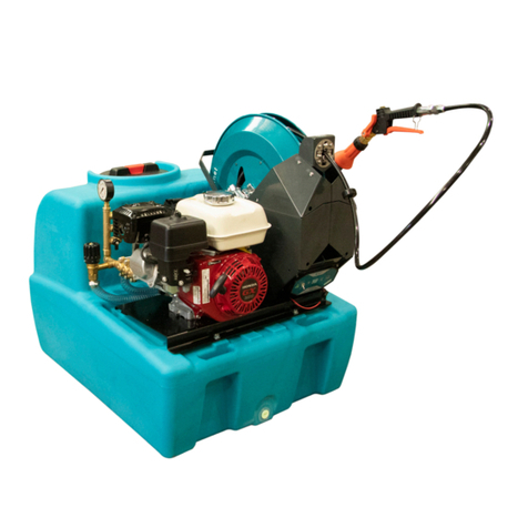
Rapid Spray Spray Marshal Plus+ SU0200AL0120H Service manual

Spray Marshal Plus+
Operator’s Handbook
SU0200AL0120H & SU0400BL0120H

Rapid Spray Marshal Unit Operator’s Handbook
Rapid Spray Equipment by Rapid Spray
Contents
01 Introduction
01 Warnings
03 Product Risk Assessment
04 Operation
05 Mixing & Filling
05 Calibration
06 Calibration Procedures
07 Calibration Guidelines for Spray Guns
07 Sprayer Decontamination
08 Maintenance
10 Unit Identification Diagram
11 Unit Specifications
11 Trouble Shooting
12 Exploded Diagram
13 Parts List
17 Warranty
19 Warranty Registration

01
Rapid Spray Marshal Unit Operator’s Handbook
Rapid Spray Equipment by Rapid Spray
Introduction
Congratulations on your purchase of a Rapid
Spray “Spray Marshal” which is complete and
ready for use. The unit is ideally suited to farmers
or spray contractors for weed spraying, fence
line spraying, spraying of drainage channels and
around buildings etc. This operator’s manual
is also applicable to the Spray Marshal model
SU0240L0120H and the SU0400AL0120H.
5. Before spraying, check the electrical and fuel
systems for damage or deterioration. Replace
parts as necessary. Do not modify equipment
or use any attachments other than those
specified by the manufacturer.
6. Select and wear appropriate Personal
Protection Equipment in accordance with
the label of the product you intend using
and your own safe work practices. Personal
Protection Equipment must still be worn while
decontaminating your sprayer. Any accidental
spills on the skin must immediately be washed
with clean water and soap.
7. Turn off the engine before filling the chemical
tank. Spray during the morning or evening
when it is cool. Intense sunlight will condense
chemicals and may cause damage. Care should
be taken when spraying in windy conditions as
spray drift may contaminate the air and may
affect the operator or damage adjacent non-
target vegetation.
Continued Over.../
Warnings
1. When mounting to any vehicle ensure that you
have read the Vehicle Owner’s Manual and that
you comply with all the weight restrictions
as specified by the vehicle manufacturer,
as overloading can cause injury or death.
Remember that 1 litre of water weighs 1
kilogram. Ensure equipment is secure during
transport.
2. To ensure your own safety and that of your
employees (if applicable) you must comply
with all relevant environmental, work place
health and safety legislation and codes of
practice.
3. You must be in good mental health to operate
this sprayer and not be under the influence
of alcohol or any drugs that could impair your
vision, physical strength, dexterity, judgement,
or other mental capacity.
4. Improper or careless use of this sprayer can
cause serious injury. Minors should never be
allowed to use this sprayer. This sprayer should
not be used when bystanders or animals are
in the area. This sprayer should never be used
while children are in the area.
REVB 03/02/2015
02
Rapid Spray Marshal Unit Operator’s Handbook
Rapid Spray Equipment by Rapid Spray
Warnings (Continued)
8. Spray only in well-ventilated areas away
from flames or cigarettes. Keep all hoses
and equipment away from the hot engine to
avoid fire hazards.
9. Do not eat, drink or smoke while spraying to
avoid ingestion of chemicals. Do not carry
or store lunch boxes or other food and drink
with spraying equipment.
10. Once the spraying operation has been
completed, decontaminate the spray
tank and spray accessories. Store any
remaining chemicals in a safe place in a
sealed container. Dispose of tank rinsings
in compliance with current environmental,
work place health and safety regulations.
11. Never leave the sprayer unattended without
turning off the engine and relieving the line
pressure, and flushing the sprayer of any
harmful chemicals.
12. Carry out maintenance once a year. Ensure
that the unit is cool and securely stabilised
on a level surface.

03
Rapid Spray Marshal Unit Operator’s Handbook
Rapid Spray Equipment by Rapid Spray
Product Risk Assessment
Task Hazards Risk Control Measures
1. Partially fill the tank with
water, connect the battery
(if applicable) & test the
spray unit.
Manual handling; slips,
trips or falls; finger
jammed; electric shock or
electrocution.
Medium Concentrate on tasks; follow safe
manual handling techniques: - don’t
lift on your own if > 20kg, bend knees
& keep back straight; keep fingers
clear; keep unit at least 8m away
from overhead powerlines; ensure
AS 3760:2001 Testing Electrical
Equipment applies; water away from
electrical sources.
2. Check weather & ground
conditions & select the
appropriate PPE to suit the
chemicals to be used.
Manual handling; slips, trips
or falls.
Low Put on PPE as per the chemical
requirements in the Material Safety
Data Sheet – coveralls, gloves, safety
footwear, glasses & respirator; follow
safe manual handling techniques: -
don’t lift on your own if > 20kg, bend
knees & keep back straight.
3. Mix chemicals & fill spray
tank units
As above; spray drift,
chemical spillage, emission
of vapours or flammability;
weather; untrained visitors.
Medium As above; user trained in the state’s
chemical mixing & administration
course e.g. Chem Cert; follow the
relevant Environment Protection
Authority requirements, fire
extinguisher present; keep visitors
away from the job unless wearing
full PPE.
4. Use spray unit As above; loss of load; work
in heat & cold; noise; exceed
load limit of vehicle; hose
entaglement; terrain &
slopes.
High As above; wear clothes to suit heat &
cold; wear hearing protection if pump
noise > 85 dBa; follow manufacturer’s
safe operation instructions for
the vehicle & the spray unit; don’t
overload-water weighs 1kg per 1 litre;
secure load to vehicle; hose tidy.
5. Clean up, maintenance &
storage.
As above. Low As above; continue to wear PPE for
clean up; store tank in a dry, well-
ventilated area.

04
Rapid Spray Marshal Unit Operator’s Handbook
Rapid Spray Equipment by Rapid Spray
PRE-START UP
• Familiarise yourself with the Unit
(see page 10 for drawing)
• Inspect unit for any broken or damaged components –
replace damaged/broken components as necessary.
• Familiarise yourself with the HONDA motor Instruction
manual (supplied with unit) and ensure you follow all
warnings and instructions contained within it.
• WARNING! Motor is shipped without oil or fuel, before
operation, fill the motor with the correct oil and fuel as
advised in the HONDA motor instruction manual.
START UP
• Confirm tank contains chemical/water.
• Push the priming pump on the carburettor several times until fuel begins to flow.
• Set the throttle lever to the LOW position. Set the choke lever to the CLOSE position when the
engine is cold.
• Turn the pressure regulating knob anti-clockwise to the BYPASS (“0” pressure) position.
• While holding the sprayer steady, grip the recoil starter handle and pull quickly.
• While checking the engine status after start-up, return the choke lever to the OPEN position.
• Allow engine to warm-up for 2-3 minutes before commencing spraying operation.
OPERATION – Manipulating the pressure regulating valve
• Turn the pressure regulating knob clockwise to increase pressure, and anti-clockwise to decrease
pressure. The sprayer requires less power when the regulating valve is set to low pressure or
the flow requirements are low. Running the engine with the throttle lever fully open will result
in unnecessary noise and increased fuel consumption. It is recommended to operate with the
throttle lever at a medium setting.
WARNING! Be aware, operating at too low a throttle setting will allow clutch to slip.
Operation
ON
OFF
Low Speed
Throle lever
Stop switch
High Speed

05
Rapid Spray Marshal Unit Operator’s Handbook
Rapid Spray Equipment by Rapid Spray
The following steps are given as a guide for the mixing and filling of the sprayer.
1. Read the product label and follow the instructions carefully, taking special note with regard to the
order in which the products are added to the tank.
2. Half-fill the spray unit with water only and commence agitation by following these steps;
• Pressure control knob must be in the bypass position. Turn the valve knob in anti-clock wise
direction to reduce pressure to “0” Bar.
• Measure the correct quantities of pesticides, using clean measuring jugs used only for this
purpose and add to the spray tank while still agitating.
• Rinse out the measuring jugs and empty containers and pour all rinsings into the spray tank.
• Top up the spray tank with clean water to the required level.
• Your spray tank should now be correctly filled and the product thoroughly mixed. Spraying can
now commence.
3. To commence spraying, rotate the pressure control knob clockwise until the desired pressure has
been reached. Open the spray gun or boom and commence spraying.
Accurate calibration is an essential element of any spraying function as it ensures that the chemical
is applied at the rate intended on the product label. Application in excess of the recommended rate is
prohibited, can damage plants/foliage and is uneconomical.
• Calibration must always be carried out:
• When spraying for the first time with new spray equipment
• At the beginning of each season
• After changes of nozzle tips, spraying pressures or speed
• After every 100 hectares of spraying
When calibrating a sprayer, a minimum of coverall, gloves and boots must be worn. A face shield and
PVC apron may be included depending on the task and the cleanliness of the equipment.
Mixing & Filling
Calibration

06
Rapid Spray Marshal Unit Operator’s Handbook
Rapid Spray Equipment by Rapid Spray
Calibration Procedures
This table gives a step-by-step guide to the standard method of sprayer calibration
Boom Sprayers Hydraulic Nozzles Example
Read the Label Spray Volume
Product Dose
Spray Quality
200 litres/hectare
50 litres/hectare
Medium
Measure TIME per
100 Metres
Measure time in seconds over land similar to that to be sprayed 41.9 seconds
Calculate SPEED SPEED = 360 divided by TIME
km/h seconds
360/41.9 = 8.6km/h
Measure nozzle
SPACING
Normally 0.5 metres (50cm) 0.5 metres
Measure TIME per
100 Metres
output = volume x speed x space ÷ 600
litres/min litres/hectare km/hr metre
200 x 8.6 x 0.5 ÷ 600
Select NOZZLE Refer to nozzle manufacturers data charts or other sources and select
the size and type of nozzle that will produce the calculated OUTPUT and
required spray QUALITY
Now, check the calibration on the sprayer
Check nozzle output With water, check outputs of 4 or more nozzles using a calibrated jug
or flow meter.
Check all nozzles are aligned correctly and spray patterns are good
Average output = 41.9
litres/minute
Calibrate SPRAYER SPEED = 360 divided by TIME
km/h seconds
1.40 x 600 ÷ 0.5 ÷ 8.6
As the nozzle output and therefore the spray volume are less than target figures, increase the pressure to, say 2.5 bar and
repeat the calibration to achieve 200 litres/hectare
Now, record the details as calculated
Nozzle Fitted 11004 - RED
Spray Volume 200 litres/hectare
Spray Pressure 2.5 bar
Spray Quality Medium
Forward Speed 8.6 km/h

07
Rapid Spray Marshal Unit Operator’s Handbook
Rapid Spray Equipment by Rapid Spray
Non-calibrated spray nozzles can lead to inaccurate application rates, spray patterns and droplet size,
which can reduce herbicide effectiveness. The first and most important step in sprayer calibration is to
choose the correct nozzle type and size for your application.
NOZZLES AND PRESSURES FOR DIFFERENT SPRAY VOLUMES
Prior to spraying, select a bush to
spray and decide what shape the
weed can be categorized as (either
dome or cylindrical). Spray that bush
normally to achieve good coverage to
the point of run-off. Time how long it
took you to spray. Repeat this process
spraying into a bucket. Measure the spray volume and compare this with the recommended spray and
water rate using the tables attached. Installing a flow meter on the high pressure hose next to the
hand gun will make calibration easier.
Spray volume Nozzle Diameter Output Pressure Psi
(L/ha) (mm) (L/min) (kPa)
1000-2000 D4 1.6 2.5 400 57
1500-3000 D5 2.0 3.8 500 71
2000-4000 D6 2.4 5.5 600 85
3000-6000 D7 2.8 7.8 700 100
4000-8000 D8 3.2 8.6 800 114
• After use, the sprayer must be thoroughly decontaminated, inside and outside – including
pump, hoses, boom and hand lance – to avoid damage to crops from harmful spray residues.
Decontamination prevents sprayer corrosion and abrasion. As a guide follow the decontamination
procedure below.
• After spraying, stabilise the unit on a level surface and allow the unit to cool. Rinse out the tank
with several changes of water plus a recommended cleaning fluid, brushing the inside of the tank.
• The suction filter mounted on the sprayer frame must be cleaned regularly. Unscrew the filter
cover and remove the filter screen and gasket. Soak in clean water, brushing with a nozzle brush.
Ensure the gasket is in position when reassembling.
• The filter basket strainer is removed by lifting it out of the filter ring. Clean the basket strainer the
same way as the suction filter. Replace the basket strainer by exerting a quick downward push to
seat the strainer correctly.
• Nozzles, nozzle filters, nozzle caps and gaskets should be cleaned by soaking in water, brushing
with a nozzle brush and allowed to dry. Never blow through the nozzles with your mouth, or use
wire or pins to clear any blockages. When reassembling ensure that the nozzle cap gasket is
correctly positioned.
Calibration Guidelines for Spray Guns
Sprayer Decontamination

08
Rapid Spray Marshal Unit Operator’s Handbook
Rapid Spray Equipment by Rapid Spray
Maintenance should be carried out regularly.
Pump Maintenance
• Check to make sure that all screws are tightened and that no parts are
missing
• Check to make sure there are no loose connections on hoses, nozzle,
lance or valves.
• Thoroughly clean the nozzle and filter (suction). Take the cap off the filter
housing and remove filter screen for cleaning. Ensure filter screen is
properly located before screwing cap back on.
Lubrication
• There are two grease cups (marked with “←” on the back of the pump)
• Always ensure grease cups are filled with grease. Screw grease cups 2-3
turns every 2 hours of operation.
Inspect the engine
• Check to make sure there are no loose or missing screws in any part of
the engine.
• Clean the air filter regularly – particularly if working in a dusty environment.
• Clean and adjust the spark plug as necessary.
• Clean the cooling fan, air intake opening and parts around the muffler.
• Check the engine oil and change it as necessary.
• Inspect the fuel line filter, check for fuel leaks.
Maintenance
Pump & motor
Lubricaon ports/
Grease cups

09
Rapid Spray Marshal Unit Operator’s Handbook
Rapid Spray Equipment by Rapid Spray
Long Term Cleaning and Storing
• When storing the sprayer, ensure that it is clean and dry and kept in a ventilated place where it
will not be subjected to freezing temperatures. Where frozen water may crack metal components
and void warranty
• Completely drain any water for the pump
• Pull the recoil starter handle slowly until there is resistance.
• After removing fuel from the tank, push the priming pump until fuel in the line runs out. Remove
fuel from the tank once more.
• Check the engine oil and change it if necessary.
• Set the throttle lever in the low speed position.
• Wipe away any dirt or dust.
943
2
6
8
7
1
5
10
943
2
6
8
7
1
5
10
OVERALL DIMENSIONS 1480(L) X 755(W) X 660(H)
ITEM CODE Description
1 AMPTC00400BFG 400 Litre Squat Tank
2,3,4 ARLP250VSR ø255 Lid Assembly
5 AMAXPM010BK 10 Litre Rinse Tank
6 ARLP100V 100mm screw lid with breather
7,8 CFNB20M 3/4” Poly Drain Bung & Seal
9 Stainless Steel Screws
10 CFVTP20M 3/4 20mm Poly Tap
OVERALL DIMENSIONS 910(L) X 730(W) X 620(H)
ITEM CODE Description
1 AMPTC00200AFG 200 Litre Squat Tank
2,3,4 ARLP250VSR ø255 Lid Assembly
5 AMAXPM010BK 10 Litre Rinse Tank
6 ARLP100V 100mm screw lid with breather
7,8 CFNB20M 3/4” Poly Drain Bung & Seal
9 Stainless Steel Screws
10 CFVTP20M 3/4 20mm Poly Tap
Dimensional Drawing – PTC00400BFGDimensional Drawing – PTC00200AFG

10
Rapid Spray Marshal Unit Operator’s Handbook
Rapid Spray Equipment by Rapid Spray
Unit Identification Diagram
Cap (Oil tank)
Hose assembly (for spraying)
Hose reel
Hose return
Crank
Filter (For sucon)Hose assembly (For sucon)
Pump
Throle lever
Stop
switch
Pressure
gauge
Pressure
regulang
valve
Recoil starter
Engine
Cap (Fuel tank)

11
Rapid Spray Marshal Unit Operator’s Handbook
Rapid Spray Equipment by Rapid Spray
Unit Specifications
Trouble Shooting
Engine Pump
MODEL GX35 Honda 4-Stroke Rapid Commando
TYPE 4-stroke, OHC single cylinder Duplex piston pump
MAX. POWER/PRESSURE 1.0kW (1.3HP) @ 7,000RPM 25BAR (360PSI)
MAX. FLOW 12L/min
OIL TYPE 10W/30 API SG SAE30/30W
OIL CAPACITY 0.1L (100ml) 0.1L (100ml)
Issue Possible Cause Resolution
Pump will not prime 1. Insufficient motor RPM
2. Air leak on suction plumbing
1. Increase motor RPM until pump
engages
2. Tighten/replace fittings
Pressure drops under load and pump
is noisy
Insufficient motor RPM to prevent
clutch slippage
Increase motor RPM
Pressure drops/fluctuates during
standard operation
1. Restriction on suction line
2. Pump sucking air
3. Residue on valves
1. Remove restriction
2. Tighten/replace fittings
3. Disassemble and clean valves/
replace broken valve springs if
necessary
Unable to get any pressure 1. Residue on valves
2. Broken regulator spring
1. Disassemble and clean valves/
replace broken valve springs if
necessary
2. Replace regulator spring

12
Rapid Spray Marshal Unit Operator’s Handbook
Rapid Spray Equipment by Rapid Spray
Exploded
Diagram

13
Rapid Spray Marshal Unit Operator’s Handbook
Rapid Spray Equipment by Rapid Spray
Parts List
No. Part Name Part Number Size Per. Set
1Engine GX35 1
2Clutch Drum CPUPP002 1
3Gearbox housing CPUPP003 1
4Housing Gasket CPUPP004 1
5Oil seal CPUPP005 17.28.7 1
6Steel Spacer 1
7O-ring CPUPP007 9x13 4
8Bearing 6201 CPUPP008 1
9Shaft 1
10 Bearing HK1010 CPUPP010 1
11 Washer CPUPP011 2
12 Bearing 608 CPUPP012 1
13 Gear shaft 1
14 Bearing 6203 CPUPP014 1
15 Bearing 6200 CPUPP015 1
16 Crank case CPUPP016 18mm 1
17 O-ring CPUPP017 G60 1
18 Crank case cover CPUPP018 1
19 O-ring CPUPP019 G25 1
20 Oil glass CPUPP020 1
21 Pump stand 1
22 O-ring CPUPP022 1
23 Drain plug CPUPP023 1
24 Screw M6x12 6
25 Nut M6 4
26 Spring washer M6 8
27 Rubber Mount CPUPP027 2
28 O-ring CPUPP028 1
29 Oil Filler Cap CPUPP029 1
30 Oil seal CPUPP030 2
31 Piston CPUPP031 18mm 1
32 O-ring CPUPP032 2
33 Fixed plate 2mm 2
34 Adjusting ring CPUPP034 2
35 Grease ring CPUPP035 2

14
Rapid Spray Marshal Unit Operator’s Handbook
Rapid Spray Equipment by Rapid Spray
No. Part Name Part Number Size Per. Set
36 V-packing upper seal CPUPP036 2
37 V-packing CPUPP037 4
38 Packing seat CPUPP038 1
39 Cylinder Head LEFT CPUPP039 1
40 Valve Assembly CPUPP040 1
40-1 Valve nut 1
40-2 Valve spring 1
40-3 Valve plug 1
40-4 Valve seat 4
40-5 Valve ring 1
40-6 Valve packing 1
41 Suction Manifold LEFT CPUPP041 1
42 Connector Nipple 2
43+44 Grease cup CPUPP043 & CPUPP044 1
45 Outlet Manifold CPUPP045 1
46 Regulator seat CPUPP046 1
47 Regulator ball CPUPP047 1
48 Regulator ball cup CPUPP048 1
49 Regulator Spring CPUPP049 1
50 Regulator valve Housing CPUPP050 1
51 Regulator Housing Nut CPUPP051 1
52 Regulator valve screw CPUPP052 1
53 Regulator knob CPUPP053 1
54 Nyloc nut CPUPP054 M6 1
55 Cylinder head RIGHT CPUPP055 1
56 Suction Manifold RIGHT CPUPP056 6
57 Outlet manifold LEFT 4
58 Elbow 1/4NPT 8
59 Pressure gauge CPUPP059 2
60 Pressure Manifold Hose CPUPP060 1
61 Suction manifold hose CPUPP061 1
62 Hose clamp CPUPP062 2
63 Bypass hose CPUPP063 1
64 Suction hose 2
66 Engine stand 1

15
Rapid Spray Marshal Unit Operator’s Handbook
Rapid Spray Equipment by Rapid Spray
No. Part Name Part Number Size Per. Set
67 Rubber Mount CPUPP067 2
68 Screw M6x45 2
69 Screw M6x75 2
70 Screw M6x12 2
71 Steel Frame CPUPP071 1
74 Screw M6x16 10
75 Hose Reel Spool CPUPP075 1
76 Hose reel swivel CPUPP076 1
77 Hose reel whip hose CPUPP077 1
78 Rubber Foot CPUPP078 4
79 Screw M8*25 4
80 Throttle mounting plate 1
81 Kill switch 1
82 Rubber sheath 1
83 Screw 3/16”x3/8”L 2
84 Washer 3/16” 2
85 Nut 3/16” 2
86 Throttle 1
87 Throttle Cable comp 1
88 Screw 2
89 Washer 2
90 Nut 2
93 Screw 2
94 Screw 2
122 Ball valve & tee piece CPUPP0122 1
Part Name Part Number Parts Included
Regulator Assembly for Rapid Commando CPUPK050
Spare Seals and Valves Kit CPUPK120 5, 7, 17, 19, 22, 28, 30, 32, 36, 37, 40
Spare Seals Kit for Rapid Commando CPUPK121 30x2, 32x2, 36x2, 37x4, 38x2
Regulator Spares Kit for Rapid Commando CPUPK122 7x3, 46x1, 47x1, 48x1, 49x1
Rubber Mount Kit for Spray Marshal CPUPK123 27x2, 67x2, 78x4, 79x4
30m Hose for Spray Marshal CPUPK130 Includes fittings
Spare Parts Kit

16
Rapid Spray Marshal Unit Operator’s Handbook
Rapid Spray Equipment by Rapid Spray

17
Rapid Spray Marshal Unit Operator’s Handbook
Rapid Spray Equipment by Rapid Spray
Warranty Policies and Procedures
The following warranty is the only warranty applicable to RAPID SPRAY products, and to the
maximum extent permitted by law, overrides any other conditions or warranties expressed or
implied on RAPID SPRAY products.
Other than legislative obligations to the contrary, RAPID SPRAY will not be liable for and
incidental or consequential damages arising from the ownership or use of a Product.
No person, including any dealer or representative of RAPID SPRAY is authorized to make any
representation or warranty on behalf of RAPID SPRAY in addition or inconsistent with these
provisions. Purchasers to whom these provisions apply agree to hold RAPID SPRAY not liable
for claims by their customers in excess of the obligations of RAPID SPRAY expressly set forth
herein.
NOTE: All tank and spray systems must have their warranty activated by returning warranty
card located at the end of this document or online www.rapidspray.net/warranty-registration
within 21 days of purchase by the end user.
The Warranty
All products sold by RAPID SPRAY are guaranteed to be free from defect in materials
workmanship or manufacture for a period of 12 months from the initial date of purchase,
excepting the following exclusions;
Any parts/products found by RAPID SPRAY to be defective, either in material or workmanship
will be replaced or repaired within this period, at no cost to the initial purchaser if following
conditions are met:
• The item has been operated in accordance with all instructions and warnings provided.
• Item is still owned and operated by original purchaser – proof of purchase is required to
obtain warranty
Warranty

18
Rapid Spray Marshal Unit Operator’s Handbook
Rapid Spray Equipment by Rapid Spray
Abuse Failure as a result of neglect, such as improper
operation. Lack of maintenance or continued operation
after discovery of a defect that leads to further
damage
Alterations Any unauthorized alteration, modification, attachments
or unauthorized repair to equipment.
Clean-Up Time RAPID SPRAY does not pay for cleaning of products,
parts or accessories or work area before or after the
warranty repair.
Damage Damages or machine/component failure caused by
carelessness/recklessness or accidental damage,
improper operation, excessive speed, inappropriate
storage or transportation.
Environmental Conditions &
Application
Deteriorated or failed components such as o-rings,
diaphragms, hoses, seals and connections damaged
by corrosive chemicals, dirt and sand, excessive heat,
moisture or other environmental impacts. Warranty
determination on these type of failures will be made
by RAPID SPRAY, only after inspection of the failed
component.
Inability | Unsuitability In no event shall RAPID SPRAY be liable to any person
for indirect or consequential damages or for injury or
commercial loss resulting from any use or inability to
use any RAPID SPRAY product.
Maintenance Component failure due to failure to perform
maintenance services such as, oil and grease changes/
top-ups, failure to clean tanks, pumps filters, nozzles
and spray lines. Failure to tighten or replace loose or
missing bolts, nuts, fittings, shields and covers.
Non-Genuine Parts Use of parts other than RAPID SPRAY parts for repair
of warranted items will automatically negate any
warranty. Warranted components must be replaced
with genuine parts.
The following things are expressly excluded from the above warranty.
This manual suits for next models
1
Table of contents
Other Rapid Spray Paint Sprayer manuals

Rapid Spray
Rapid Spray SPOT RANGER Service manual

Rapid Spray
Rapid Spray FIELDLINK ECO Service manual

Rapid Spray
Rapid Spray RapidLine SVL0020L0038 Service manual

Rapid Spray
Rapid Spray CHAPIN 79903 User manual

Rapid Spray
Rapid Spray BUDDY SMART REEL Service manual

Rapid Spray
Rapid Spray MARSHAL PRO Series Service manual