Rongpeng R805 User manual

- 1 -
AIR-POWERED SPRAY GUN
TOUCH UP SPRAY GUN
MODEL
INSTRUCTION MANUAL
IMPORTANT:
Read all safety rules and operating Instructions
carefully before starting the product.
Keep this Manual for future reference.
Residual Risks
Even when the tool is used as prescribed it is not possible to eliminate all residual risk factors.
The following hazards may arise in connection with the tool’s construction and design:
Wear gloves and respirator.
2018
R805

- 2 -
TABLE OF CONTENTS:
DESCRIPTION
TECHNICAL DATA
IMPORTANT SAFETY INSTRUCTION
KEY PARTS DIAGRAM
INSTRUCTIONS FOR OPERATION
MAINTENANCE
TROUBLESHOOTING
EXPLODED VIEW
PARTS LIST
Description
This VALU-AIR Air-powered Gravity-feed Spray Gun is a TOUCH UP sprayer. This tool applies paint
with less force, reducing the bounce of the material from the surface to be painted. It features a stainless steel
needle and nozzle to accommodate a variety of coatings. The spray gun is capable of forming very large
patterns.
Technical Data
TPYE:
R
Recommended air pressure 3.0-4.0bar
Type of Feed
Gravity
Max. pressure of air 4.0 bar (58psi)
Air inlet
1/4”
Avg. Air Consumption 3.5-6.0cfm
Standard Nozzle
0.8mm
Pattern Width 110-160mm
Optional Nozzle
0.8,1.0mm
Paint Capacity 125cc plastic cup
Important Safety Instructions
1. For toxic vapors produced by spraying certain materials can create intoxication and
serious damage to health. Always wear safety glasses, gloves and respirator to
prevent the toxic vapor hazard, solvent and pointing paint coming into contact your
eyes or skin. (see fig 1)
2. Never use oxygen, combustible or any other bottle gas as a power source or would
cause explosion and serious personal injury. (see fig 2)
3. Fluid and solvent can be highly flammable or combustible. Pls Use the tool only in
well-ventilated area, and avoid any ignition sources, such as smoking, open flames
and decrial hazard. (see fig 3)
4.Disconnect tool from air supply hose before doing tool maintenance and during
non-operation, for emerge stop and prevention of unintended operation, a ball valve
near the gun to air supply is recommend.
5. Use clean, dry and regulate compressed air rated at 3.0-4.0bar, never exceed
maximum permissive operating pressure 4.0bar (58psi) (see fig 4)
6. Never use homogenate hydrocarbon solvent, which can chemically react with
aluminum and zinc parts and chemically compatible with Alum. and zinc pats.
7. Never point gun at you and others at any time.
8. Before operating the tool, make sure all the screws & caps are securely tightened in case of leaking;
9. Before painting, make inspection for free movement of trigger and nozzle to insure tool can operate well.
10. Never modify this tool for any other applications. Only use parts, nozzles and accessories recommended
and accessories recommended by manufactures.
1
图表 1
2
3
4
805

- 3 -
Instructions For Operation
Key parts Diagram
1. Fluid Control: Controls the volume ofmaterial that travels through the fluidtip.
2. Pattern Control:Adjusts the spray pattern from a round pattern to a wide fan.
3. Air Flow Control: Controls the fluid pressure inside the spray gun.
4. Cap, nozzle and needle: Controls the spray pattern from vertical to horizontal.
5. Trigger: Two stage trigger. Stage one only releases compressed air for blowing off the work piece. Stage
two sprays material.
6. Cup: 125 ml cup allows for easy clean-up. Includes a vented cap.
Assembly
1. Insert the filter into the gun body
2. Screw the cup onto the top of the body.
3. Install the barbed hose fitting into the base of the gun handle and tighten in place with the lock nut.
4. Secure the air hose to the barbed fitting with a hose clamp.
5. Attach the spray gun to an air hose regulated between 43.5 and 58 PSI .
Preparation
1. After unpacking the product, inspect carefully for any damage that may have occurred during transit. Make
sure to tighten fittings, bolts, etc., before putting unit into service.
2. Thoroughly mix and thin paint in accordance with the paint manufacturer’s instructions. Most materials will
spray readily if thinned properly.
3. Strain material through filter, cheese cloth or a paint strainer.
4. Fill the canister about ¾ full and start the air compressor.
Cap, nozzle and needle
Cup
Fluid Control
Trigger
Air Flow Control
Pattern Control

- 4 -
WARNING DO NOT EXCEED Maximum Pressure of Spray Gun or any other parts in the compressor system.
5. After Connect the gun to air supply, please make sure that the fluid cap, container and air hose have been
connected tightly with spray gun.
6. Set up a piece of cardboard or other scrap material to use as a target and adjust for best spray pattern.
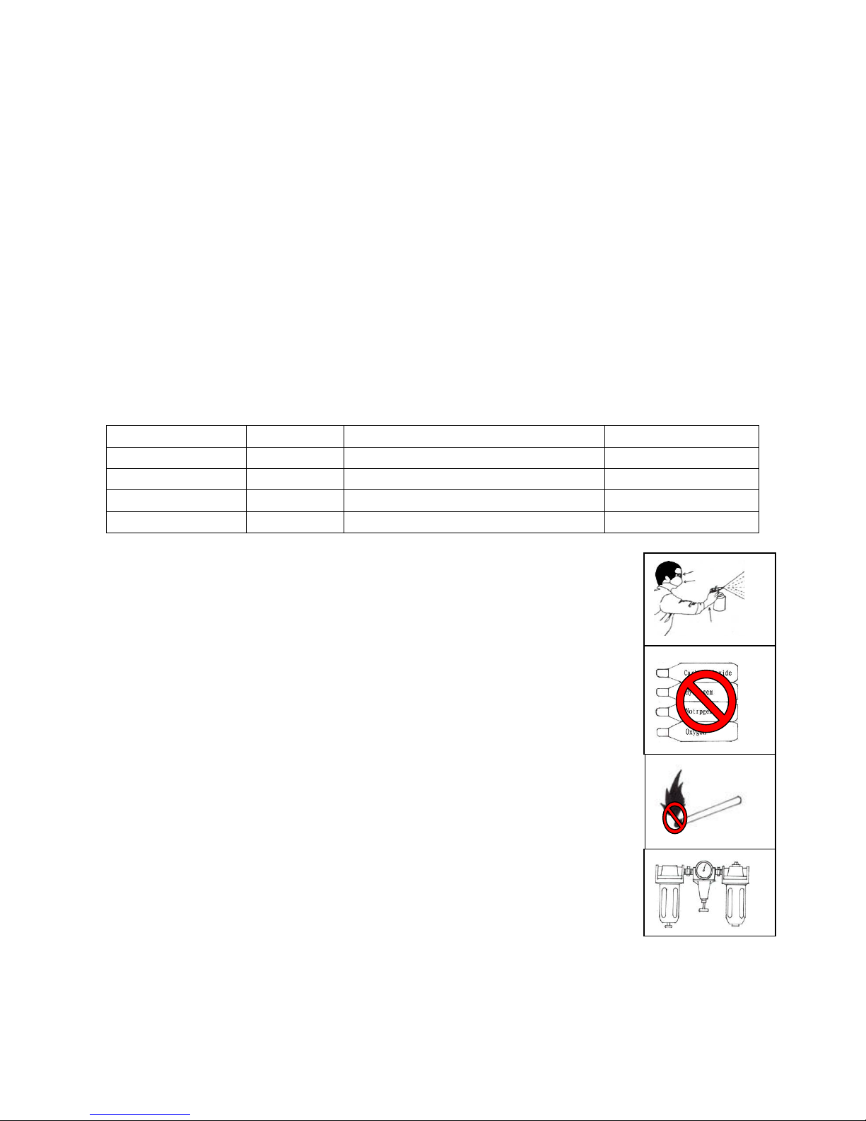
WARNING Never aim or spray at yourself or anybody else which would cause serious injury.
7. Test the consistency of the material by making a few strokes on a cardboard target. If material still appears
too thick, add a small amount of thinner. THIN WITH CARE! Do not exceed paint manufacturer’s thinning
recommendations.
Operation
1. Begin spraying. Always keep the gun at right angles to the work .
2. Keep the nozzle about 6 to 12 inches from the work surface. Grip the gun keeping perpendicular with
spraying area then move it parallel for several times, Stopping gun movement in mid-stroke will cause a
build up of paint and result in runs. Do not fan the gun from side to side while painting. This will cause a
build-up of paint in the center of the stroke and an insufficient coating at each end.
3. Trigger the gun properly. Start the gun moving at the beginning of the stroke BEFORE SQUEEZING THE
TRIGGER and release the trigger BEFORE STOPPING GUN MOVEMENT at the end of the stroke. This
procedure will blend each stroke with the next without showing overlap or unevenness .
4. The amount of paint being applied can be varied by the speed of the stroke, distance from the surface and
adjustment of the fluid control knob.
5. Overlap strokes just enough to obtain an even coat.
NOTE: Two thin coats of paint will yield better results and have less chance of runs than one heavy layer.
6. Use a piece of cardboard as a shield to catch overspray at the edges of the work to protect other surfaces.
Atomizing Cap and Fan Adjustments
1.The atomizing cap needs to be adjusted for horizontal or vertical spraying patterns. Spraying in the wrong
direction may lead to material build up on the atomizing cap horn. Many performance problems are caused by
clogged atomizing holes on the atomizing cap horns (see Cleaning).
2.Rotating the pattern adjustment control in will give you a range between the two patterns in Figure 8. .

- 5 -
Maintenance
Incomplete cleaning could cause function failures and a degradation of the fan form.
Proper cleaning is the best way to ensure trouble free performance from your spray gun. If your gun is not
thoroughly cleaned, damage and poor spraying will result. Problems caused by improper cleaning will not
be covered by the warranty. Clean the spray gun immediately after each use.
To clean your spray gun:
1. Spray a small amount of solvent through the spray gun.
Note: Check with local laws regarding this practice. If you are spraying on a regular basis, spraying
solvents into the air may be illegal. A cabinet style spray gun cleaner may be required.
2. Disconnect the gun from the compressed air!
3. Unscrew the cup.
4. Disassemble the gun by unscrewing the fluid control knob, removing the spring and needle.
5. Unscrew the atomizing cap with your fingers and the fluid tip with the service wrench. The fully
disassembled gun should look like Figure 9.
6. Rinse these parts thoroughly in solvent then dry with compressed air or let air dry.
Note: If the small holes in the atomizing cap become blocked, soak in clean solvent. If the blockage still
exists, clear the blockage with a small needle, taking great care to not enlarge or damage the hole.
Damage to the hole will create a disrupted spray pattern.
7. Use the cleaning brush with solvent to clean the inner orifice and other hard to reach areas on the outside
of the spray gun body.
8. Wipe the rest of the gun body with a shop towel and dry.
Clean the inside and outside of the spray gun(1)with a brush(2).
Clean the inside of the paint cup (1).

- 6 -
Remove and clean the inside and outside of the air cap with a brush soaked in cleaning solvent.
Note: Wash the air cap(1) carefully without causing any damage to its air hole as this would affect the
spraying pattern. Never use a steel wire or wire brush for cleaning.If the air hole is clogged, clean it using a
wooden toothpick(2).
WARNING:
NEVER USE METAL OR OTHER OBJECTS THAT COULD DAMAGE THE HOLES IN THE NOZZLE AND CAP. NEVER
IMMERSE THE SPRAY GUN COMPLETELY IN SOLVENT. NEVER USE COMPONENTS OR PARTS THAT ARE NOT
MANUFACTURER ORIGINALS.
Storing
When not using spray gun, turn the fluid adjustment knob counter-clockwise to open which
will reduce spring tension on needle fluid tip.
Spray gun MUST BE well cleaned and lightly lubricated.

- 7 -
Trouble shooting
WARNING Potential hazard that could result in serious injury or loss of life.
• If any of the following symptoms appear while the tool is in use, turn it off and disconnect it from the air supply
immediately. Failure to heed this warning could result in serious personal injury.
• Disconnect electrical plug and air supply from the tool before making any adjustments.
• Repairs must be performed by a qualified service technician only.
Symptom
Problems
Solution
Fluttering or
spitting
1. Dry or worn fluid tip seat permits
air to seep into fluid passage.
2. Material level too low.
3. Fluid tip or strainer obstructed.
4. Dry needle packing.
1. Tighten fluid tip or replace seat with
new one.
2. Add material.
3. Clean
4. Lubricate needle.
Uneven top or
bottompattern.
1. Atomizing cap holes are obstructed.
2. Build-up on top or bottom of fluid tip.
3. Build-up on atomizing cap is on needle seat.
1. Clear holes.
2. Clean.
3. Clean.
Right or left arc pattern.
1. Left or right side horn holes are plugged.
2. Build-up on left or right side of fluid tip.
3. Build-up of material inside atomizing cap.
1. Clear holes.
2. Clean.
3. Clean.
Heavy deposit of
material in center.
1. The material flow exceeds the atomizing cap
capacity.
2. Inlet air pressure is too low.
3. Material is too thick.
1. Lower fluid flow.
2. Increase inlet air pressure.
3. Thin material.
Narrow center pattern.
1. Volume control turned in too far.
2. Inlet air pressure too high.
3. Fluid pressure is too low.
4. Material is too thin.
1. Increase volume.
2. Reduce inlet air pressure.
3. Increase fluid pressure.
4. Adjust material.
Excessive overspray.
1. Fluid pressure too high.
2. Gun is too far from surface.
3. Spraying too fast.
1. R educe fluid pressure.
2. Keep gun at recommended distance.
3. Slow down and maintain consistent, even parallel stroke.
Unable to control
spray fan.
1. Pattern adjustment screw is not seating properly.
2. Atomizing cap is loose.
1. Clean or replace.
2. Tighten atomizing cap.
Runs and sags.
1. Damaged seal.
1. Replace damaged seals.
Material leaks from
cup.
1. Cap not secure.
2. Cup not tight on gun body.
3. Leaking from cap vent hole.
1. Tighten.
2. Tighten.
3. H old gun upright do not tilt.
Thick dimpled finish
aka "Orange Peel."
1. Holding gun too close to surface.
2. Inlet air pressure too low.
3. Material not properly mixed.
4. Surface is dirty or oily.
1. S pray at recommended distance.
2. Check inlet air pressure.
3. Follow manufacturer's instructions.
4. More surface
Dry Spray.
1. Inlet air pressure too high.
2. Gun too far from surface.
3. Gun stroke too fast.
1. Lower inlet air pressure.
2. Keep gun at recommended distance.
3. Slow down and maintain consistent even parallel stroke.
Gun leaks from fluid tip.
1. Debris will not let the needle
seat with the fluid tip.
1. Clean or replace both.
Contaminated paint.
1. Water or oil in the air line.
1. Install an in-line air filter.
2. Replace air line.

- 8 -
Explode view & Parts List
NO.
Description
Qty.
NO.
Description
Qty.
NO.
Description
Qty.
1
Air Adjustment Knob
1
17
Nut Sleeve
1
33
Cup cover
1
2
Air Adjustment Seat
1
18
O-ring 17*1.5
1
34
Hex nut
1
3
O-ring 2.5x2.1
1
19
Nozzle
1
35
Needle
1
4
Gasket
1
20
Nozzle Gasket
1
36
Needle spring
1
5
Air Inlet Spring
1
21
Guide Bolt
1
37
Nut
1
6
Air Valve Stem
1
22
Needle Sealing Gasket
1
38
Paint Adjustment Knob
1
7
Trigger Spring
1
23
Sealing Ring
1
39
Bolt
1
8
Trigger Stem
1
24
Depress Spring
1
40
Pattern Adjustment Nut
1
9
Foam Gasket
1
25
Trigger Pin Ⅰ
1
41
Pattern Adjustment Knob
1
10
O-ring 4.9x1.5
1
26
Trigger Pin Ⅱ
1
42
O-ring 2*1.5
1
11
Trigger Seat
1
27
Trigger
1
43
Snap Retainer d=2.5
1
12
Sealing Ring
2
28
Snap Retainer d=3
2
44
Pattern Adjustment seat
1
13
Sealing Screw
1
29
Cup
1
45
Gun body
1
14
Air Cap Nut
1
30
Collar nut
1
46
Air inlet plug
1
15
Air Cap Gasket
1
31
Filter
1
16
Air Cap
1
32
Paint Inlet Plug
1
Note:
If you need spare parts of this model, pls feel free to contact us or the distributor where you bought this tool.
Tks!
Table of contents
Other Rongpeng Paint Sprayer manuals