Raptor Photonics HAWK 252 User manual

1
HAWK-252/USER-MANUAL/REV1.0/02-20
HAWK 252
Model: HK252-CL
USER MANUAL

2
HAWK-252/USER-MANUAL/REV1.0/02-20
CONTENTS
1. INTRODUCTION................................................................................................................................. 3
1.1 Scope ............................................................................................................................................ 3
2. CAMERA CARE ................................................................................................................................. 3
2.1 Cleaning the Sensor Window........................................................................................................ 3
3. SPECIFICATION ................................................................................................................................ 4
3.1 Camera Overview ......................................................................................................................... 4
3.2 Datasheet ...................................................................................................................................... 4
4. DESIGN OVERVIEW .......................................................................................................................... 5
4.1 Mechanical Model ......................................................................................................................... 5
4.2 Physical Interface .......................................................................................................................... 6
4.3 Power Consumption ...................................................................................................................... 6
4.4 Mounting to a Tripod or Optical Table........................................................................................... 6
5. SOFTWARE COMPATIBILITY .......................................................................................................... 7
5.1 XCAP Compatibility ....................................................................................................................... 7
5.2 Custom Software Interfacing......................................................................................................... 7
6. CAMERA SETUP AND REQUIREMENTS ........................................................................................ 8
6.1 Connecting the Camera to the Frame Grabber ............................................................................ 8
6.2 Computer/Laptop System Requirements...................................................................................... 8
6.3 Frame Grabber Requirements ...................................................................................................... 8
7. XCAP IMAGING SOFTWARE............................................................................................................ 9
7.1 Downloading and Installing XCAP ................................................................................................ 9
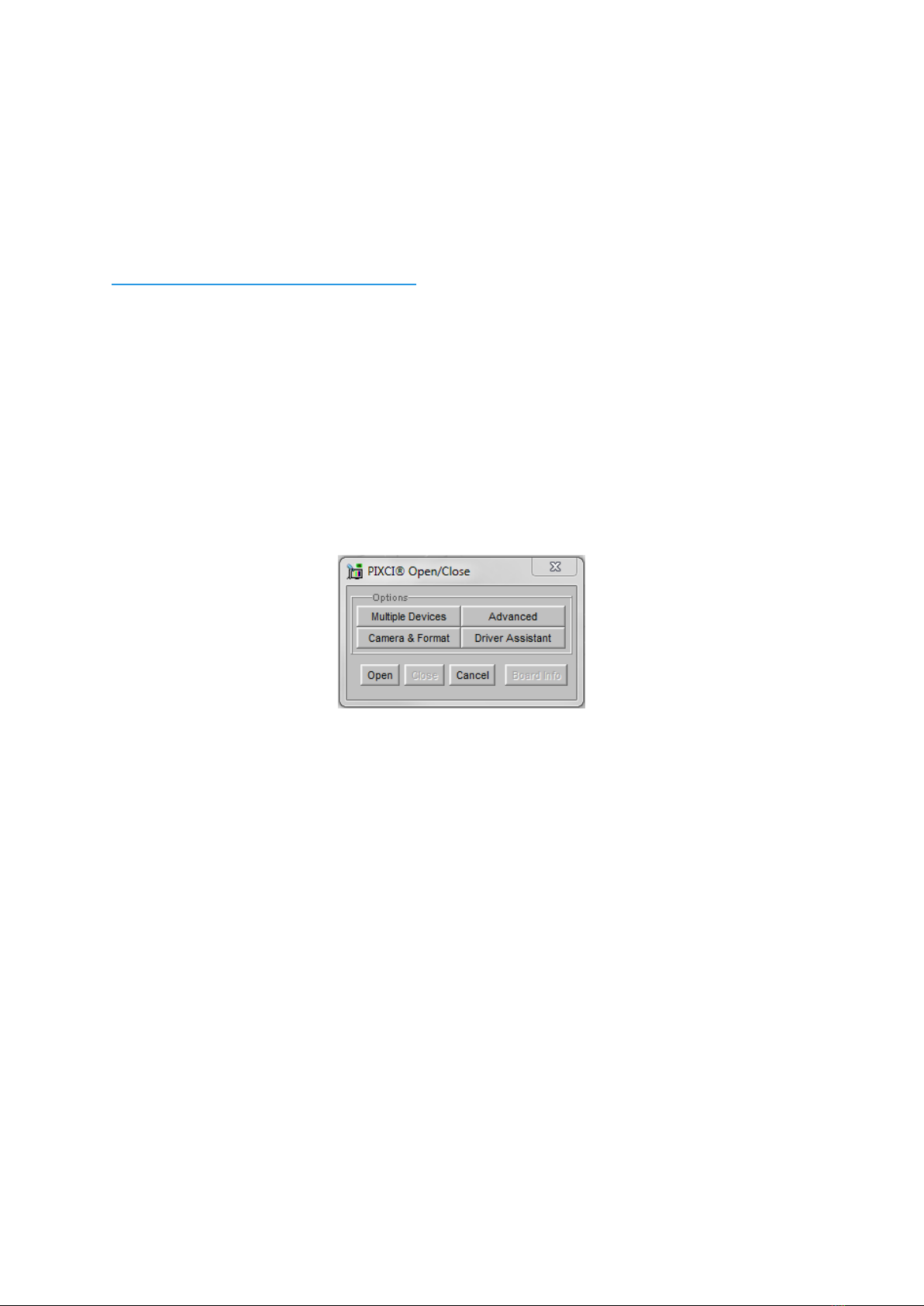
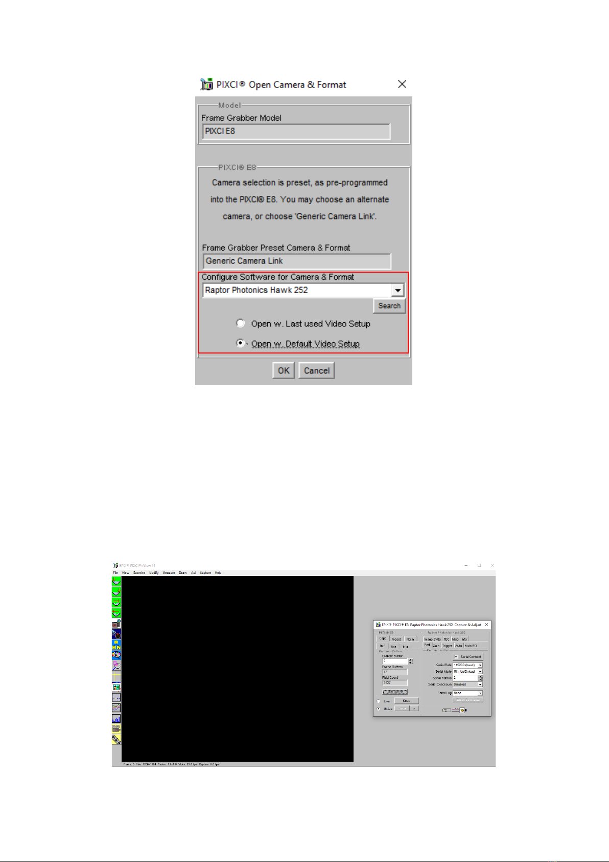
7.2 Opening the Camera Configuration .............................................................................................. 9
7.3 Acquiring a Live Image Sequence .............................................................................................. 11
8. CONTROLLING THE CAMERA (XCAP) ......................................................................................... 12
8.1 Exposure and Gain Control......................................................................................................... 12
8.2 Frame Rate and Triggering Modes ............................................................................................. 13
8.3 Automatic Light Control Adjustment............................................................................................ 14
8.3.1 Automatic Light Control Parameters .................................................................................... 14
8.3.2 Automatic Light Control Region of Interest ..........................................................................15
8.4 Image State ................................................................................................................................. 16
8.5 Thermoelectric Cooler ................................................................................................................. 17
8.6 Horizontal Flip and Micro Reset .................................................................................................. 18
8.7 Manufactures Data ...................................................................................................................... 19
9. XCAP CONTROL FEATURES......................................................................................................... 20
9.1 Saving Preset Settings................................................................................................................ 20
9.2 Contrast Modification (XCAP Std. Only) ..................................................................................... 21

3
HAWK-252/USER-MANUAL/REV1.0/02-20
1. INTRODUCTION
This document provides detailed instructions for the operation of the Hawk 252 EMCCD
camera. Raptor Photonics Limited reserves the right to change this document at any time
without notice and disclaims liability for editorial, pictorial or typographical errors.
1.1 Scope
This manual covers the Hawk 252 digital camera and all applicable components. Raptor
recommends that this manual be used to optimize camera operation. Details of the camera’s
mechanical and electrical interfaces are provided, as well as information on the camera
controls. Important precautions to be taken when using the camera are also stated.
Detailed information is also provided on each of the cameras control parameters. Each
camera control is discussed and explained with the use of XCAP Imaging software, which is
the core plug and play software package that is offered with Raptor cameras. An image of
the Hawk 252 is shown in Figure 1.
2. CAMERA CARE
2.1 Cleaning the Sensor Window
Raptor cameras require no regular maintenance except occasional external cleaning of the
sensor window (the glass window between the camera sensor and the microscope or lens).
Use optical grade isopropyl to clean this window. A cotton swab can be used, but may leave
some fibres on the window, so be careful. To avoid this, you could also use a lens tissue or a
cleaning swap such as a texwipe. Forced air can be applied to remove any loose particles.
Should any other issues occur please contact your local agent.
CAUTION — The camera’s sensor and circuits are sensitive to static discharge. Ensure that
you are using a static strap or completely grounded at all times to release any static energy
before you clean the window.
CAUTION — Do not use acetone.
Figure 1: Complete Camera Module.

4
HAWK-252/USER-MANUAL/REV1.0/02-20
3. SPECIFICATION
3.1 Camera Overview
The Hawk 252 is designed for applications that require high sensitivity and resolution (1280 x
1024). The camera is a cooled HD EMCCD, with back-illuminated EMCCD technology,
enabling ultimate sensitive imaging (<50μlux). High-speed low-noise electronics provide linear
response and sensitivity for rapid image capture.
The Camera Link digital interface provides the most stable platform for data transfer and the
camera will work on any Camera Link standard frame grabber.
3.2 Datasheet
For the full specification of the Hawk 252, the datasheet for the camera can be downloaded
from the Raptor Photonics website:
https://www.raptorphotonics.com/products/hawk-252/

6
HAWK-252/USER-MANUAL/REV1.0/02-20
4.2 Physical Interface
4.3 Power Consumption
Unit input power specification is +12V DC +/- 0.5V with <15W power dissipation when the
TEC is disabled. An additional 5W may be required if the full drive to the TEC is required.
This will be dependent on environmental conditions and the TEC temperature set point.
The set point for the TEC cooling is +15 °C. The TEC power is automatically adjusted to try
and achieve the set point temperature. For low ambient temperatures or with additional heat
sinking, less than 5W may be applied to the TEC to achieve the set point.
4.4 Mounting to a Tripod or Optical Table
The camera has a ¼-20 BSW (Whitworth), threaded hole to mount to a tripod or an optical
table.
2
3
4
1
1. 3M CameraLink connector
(TyOUT)
Part #: 12226-1150-00FR
2. SMA connector: Trigger Out.
Single ended, source impedance =
51 Ω, capable of sinking and
sourcing 32mA and will have an
output voltage of 3.3v i.e. TTL
compatible.
3. SMA connector: Trigger In.
Single ended, termination impedance
= 510 Ω, capacitive load = 200 pF,
TTL compatible.
4. 4 Pin Hirose connector
Part #: HR10A-7R-4PB(73)

7
HAWK-252/USER-MANUAL/REV1.0/02-20
5. SOFTWARE COMPATIBILITY
This section outlines the options relating to software that are available for the Hawk 252.
5.1 XCAP Compatibility
Raptor works closely with EPIX who integrate all Raptor camera models into their XCAP
Imaging Software package. XCAP is the core plug and play software package that is offered
with all Raptor cameras.
5.2 Custom Software Interfacing
The EPIX frame grabbers are the models that we offer with our cameras. We offer their
Software Development Kit (SDK) for interfacing with custom software (XCLIB). If using a
frame grabber from a different company, then you will have to obtain their SDK. Raptor can
provide a full ICD with all serial settings and serial commands to control the camera. This,
along with the SDK that you obtain, will enable you to integrate the camera into a custom
software package.

8
HAWK-252/USER-MANUAL/REV1.0/02-20
6. CAMERA SETUP AND REQUIREMENTS
This section will give instruction on setting up the camera with the frame grabber and also
states important requirements for the frame grabber and PC.
6.1 Connecting the Camera to the Frame Grabber
The Hawk 252 uses base Camera Link configuration, so therefore requires a frame grabber
that supports base Camera Link. The frame grabber that Raptor offer with this camera is the
EB1 model from EPIX. When using this frame grabber, one MDR – SDR Camera Link cable
is required to connect the camera to the frame grabber.
If demoing the camera with the Mini PC system that Raptor provides, you should connect the
left port of the frame grabber to the SDR port on the camera interface. This should be
labelled on the mini PC that is sent with the demo kit.
6.2 Computer/Laptop System Requirements
The basic system requirement is that the PCIe bus of the system must provide sufficient
bandwidth to handle video rate transfers. The amount of bandwidth required depends on the
camera in-hand. The Owl 640 S uses a base Camera Link interface which can be handled
with a x1 PCIe bus and PIXCI EB1 from EPIX, providing roughly 200MB/sec maximum
bandwidth. Contact EPIX Inc. for further information regarding minimum computer/laptop
specification requirements to run the XCAP Imaging Software.
6.3 Frame Grabber Requirements
It is a minimum requirement to use the EB1 frame grabber model if using EPIX. If using
another frame grabber from a different company, the specification of this frame grabber must
match that of the EB1 model.
If using a laptop, EPIX offers base Camera Link frame grabbers for a laptop system, such as
the ECB1/ECB1-34.

9
HAWK-252/USER-MANUAL/REV1.0/02-20
7. XCAP IMAGING SOFTWARE
This section will discuss downloading and installing XCAP, as well as acquiring an initial
image using the software package.
7.1 Downloading and Installing XCAP
The latest version of XCAP can be downloaded from the link below:
http://www.epixinc.com/support/files.php
please select the appropriate version of XCAP for your computer. Ensure that you download
from the section labelled “Pre-release version with support for the latest cameras and
latest PIXCI® imaging boards”.Open the downloaded file when complete and follow the
onscreen instructions in the installation wizard. If a pop-up message appears asking whether
to install the PIXCI driver, ensure that you click yes.
7.2 Opening the Camera Configuration
After opening XCAP, select “PIXCI Open/Close” from the “PIXCI” tab from the top menu bar
in the main window. A PIXCI Open/Close pop-up box will open as shown in Figure 2.
Click on “Camera & Format” that is highlighted in Figure 2 and a “PIXCI Open Camera &
Format” box will appear, as shown in Figure 3.
Figure 2: PIXCI Open/Close.

10
HAWK-252/USER-MANUAL/REV1.0/02-20
Using the dropdown menu highlighted, search for “Hawk 252”, which will bring up the Raptor
Photonics Hawk 252 camera configuration. Select ok on this configuration. Selecting “Open
w. Default Video Setup” will open the control panel with all control parameters set to the
default states. “Open w. Last used Video Setup” will open the control panel with all
parameters set at the last known state. Once this option between the two has been selected,
click “Ok”. To open the camera control panel and imaging window, click “Open” in the “PIXCI
Open/Close” window (Figure 2).
Two windows will now open in XCAP, and imaging window and control panel, as shown in
Figure 4.
Figure 3: PIXCI Open Camera & Format.
Figure 4: Imaging Window & Control Panel.

11
HAWK-252/USER-MANUAL/REV1.0/02-20
7.3 Acquiring a Live Image Sequence
There are two things to observe in the control panel that inform you that the camera is
connected and ready to image.
The serial connect checkbox must be ticked in the control panel. This informs you that you
have established a serial connection with the camera and can control the camera.
Secondly, the symbol near the bottom right of the control panel will have three moving dots.
This indicates that you are obtaining video data from the camera. The imaging statistics
displayed directly underneath the imaging window will also inform you if you are receiving a
video feed from the camera.
Once you have established a serial connection with the camera and are receiving video
data, you can now grab a live image feed. Clicking the “Live” button will grab a live image
sequence which you will now see in the imaging window.
When the camera is grabbing a live image sequence, you should immediately enable
contrast modification. Instructions on how to do this can be seen from section 10.2.
The symbols in the control app discussed above are displayed in Figure 5.
Figure 5: Checking Camera Connection and Acquiring a Live
Image.

12
HAWK-252/USER-MANUAL/REV1.0/02-20
8. CONTROLLING THE CAMERA (XCAP)
The sections below give information on using each control of the Hawk 252, giving a
description on how to use each control parameter and their effect on the camera’s
performance. The software used to illustrate the camera controls is XCAP.
8.1 Exposure and Gain Control
The exposure and gain (EM and digital) can be controlled automatically by using the
Automatic Light Control (ALC). When the ALC is enabled, the camera will automatically
adjust the exposure and gain of the camera based on the ALC parameters set. Adjusting the
ALC parameters is discussed in section 8.3.
If the ALC is disabled, the user will be able to select EM and digital gain values. Please take
great caution when manually controlling the EM gain. Using excessive levels of EM Gain
when not required can possibly cause damage and aging of the sensor. Raptor recommends
using the ALC to automatically control the EM gain.
The gain controls are shown in Figure 6.
Figure 6: Gain Controls.

13
HAWK-252/USER-MANUAL/REV1.0/02-20
8.2 Frame Rate and Triggering Modes
The frame rate state and trigger mode of the camera can be controlled from the “Trigger” tab
of the XCAP GUI, shown in Figure 7.
Currently, the camera runs only at 25Hz. This will eventually be adjusted so that a few
different discrete frame rate options can be selected.
The trigger state of the camera can also be adjusted. By default, the camera is set to Internal
trigger mode, Integrate Then Read. If wanting to externally trigger the camera, this can be
performed by selecting “Ext. Trigger” from the “Trigger Mode” dropdown box.
Figure 7: Frame Rate and Trigger Mode Controls.

14
HAWK-252/USER-MANUAL/REV1.0/02-20
8.3 Automatic Light Control Adjustment
The ALC can be fine tuned by adjusting a few different parameters. A Region of Interest
(ROI) of pixels can also be defined in which to drive the ALC. These controls are discussed
below.
8.3.1 Automatic Light Control Parameters
Peak and average video levels are derived and monitored for the active ROI and are used to
drive the ALC. The active video level used to compare to the set point can be adjusted from
full average to full peak or a percentage of both. The percentage used of the average and
peak video levels can be adjusted from the “Auto” tab in the XCAP GUI. An explanation of
the average and peak video levels are stated below.
Average Video Level: An average video level is calculated for the active ROI. This value
will be calculated in real time, i.e. as pixel data in the ROI is captured from the sensor, it is
fed directly to an accumulator. At the end of the frame, the accumulator is divided to give a
true average.
Peak Video Level: The peak video is determined from a rolling average of 4 pixels. Current
pixel + 3 previous pixels are used to derive a peak value. This peak value is monitored for
the ROI and latched at the end of frame.
Selecting a greater percentage from the average will drive the ALC to use greater exposure
and gain values. Selecting a greater percentage from the peak will have the opposite effect.
ALC Level: The ALC level can also be adjusted to fine tune the ALC. Increasing the level
will cause greater exposure and gain values to be set by the ALC. Decreasing the level will
have the opposite effect.
Both controls can be adjusted depending on the performance of the ALC in the current
imaging scene conditions set.
Figure 8: ALC Parameters.

15
HAWK-252/USER-MANUAL/REV1.0/02-20
8.3.2 Automatic Light Control Region of Interest
A Region of Interest (ROI) within the main active region of 1280 x 1024 may be defined. This
region is used to calculate peak and average video levels to drive the Automatic Light
Control (ALC) function of the camera (discussed in section 8.3.1).
The ROI offset and sizes are outlined in Figure 9.
The active ROI for the ALC can be adjusted from the “Auto ROI” tab in the XCAP GUI,
shown in Figure 10.
The ROI can be moved to within a resolution of 8 pixels in the X and Y axis and the ROI size
will have a resolution of 8 pixels. The default ROI settings are shown in Figure 10.
An optional ROI outline feature can be enabled that highlights a 1 pixel wide box around the
active ROI set. This can be enabled by selecting “ROI Box” from the “ROI Highlight”
dropdown box.
Figure 9: Region of Interest Size and Offset.
Figure 10: Region of Interest Size and Offset Controls.

16
HAWK-252/USER-MANUAL/REV1.0/02-20
8.4 Image State
The image state of the camera can be adjusted from the “Image State” tab in XCAP. The
camera has four different image state options:
•Gain Corrected
•Raw Data
•Test Pattern 1
•Test Pattern 2
By default, the camera will be running in “Gain Corrected” which is what Raptor recommends
using the camera in. If wanting to obtain the raw data from the camera without the gain
correction, the “Raw Data” state can be used.
There are two different test patterns which can also be enabled.
This controls are shown in Figure 11.
Figure 11: Image State Control.

17
HAWK-252/USER-MANUAL/REV1.0/02-20
8.5 Thermoelectric Cooler
The Thermoelectric Cooler (TEC) can be controlled from the “TEC” tab of the XCAP GUI, as
shown in Figure 11.
By default, the TEC will be enabled and set to 15 C. This is the optimum temperature of the
camera and the sensor temperature that the gain correction is performed. Raptor
recommends keeping the TEC set point at 15 C. The TEC set point can be set lower, but
there is a delta limit between the sensor and PCB temperature. Therefore, there will have to
be adequate heat sinking if wanting to use a lower set point. If imaging in an ambient around
room temperature, it may be difficult to hold a set point lower than 15 C.
The sensor temperature can also be read back by clicking “Update Temp”.
Figure 12: Thermoelectric Cooler.

18
HAWK-252/USER-MANUAL/REV1.0/02-20
8.6 Horizontal Flip and Micro Reset
The “Misc” tab on XCAP has the controls for the horizontal flip and the micro reset, shown in
Figure 13.
By default, the camera will have horizontal flip enabled, which flips the image in the Y axis.
There is also a button that enables a micro reset of the camera if required.
Figure 13: Miscellaneous Tab.

19
HAWK-252/USER-MANUAL/REV1.0/02-20
8.7 Manufactures Data
The “Info” tab displays the manufacturers data of the camera, such as the firmware version,
serial number etc. The sensor and PCB temperature can also be read from this tab. The
“Info”tab is shown in Figure 14.
Figure 14: Manufactures Data.

20
HAWK-252/USER-MANUAL/REV1.0/02-20
9. XCAP CONTROL FEATURES
XCAP has many different control functions and analytical tools that can be used when
imaging the camera. For the full XCAP user guide, please refer to the link below:
http://epixinc.com/manuals/pixci_e14el/index.htm
This section will discuss in detail a few features on XCAP that Raptor thinks would be of
immediate use when using the camera.
9.1 Saving Preset Settings
Different camera and frame grabber settings can be saved in the “Preset” tab under the
PIXCI (relevant frame grabber model number) section of the GUI, as shown in Figure 12.
Up to three different presets can be saved per settings file. If the camera is set to a desired
state outside of the default state, clicking “Save 1” will save all the current parameter states
that have been set.This can be done a further two times. These camera states can be
recalled at any time by using the recall buttons. The overall settings file can then be saved
and loaded in this tab also. Three preset states is the maximum number that can be saved in
a settings file.
Figure 15: Preset Settings.
This manual suits for next models
1
Table of contents
Other Raptor Photonics Digital Camera manuals

Raptor Photonics
Raptor Photonics Owl 640 II Series User manual

Raptor Photonics
Raptor Photonics Hawk User manual

Raptor Photonics
Raptor Photonics OWL 640 M User manual

Raptor Photonics
Raptor Photonics OWL 1280 User manual

Raptor Photonics
Raptor Photonics Ninox 640 SU User manual

Raptor Photonics
Raptor Photonics OWL 640 S User manual

Raptor Photonics
Raptor Photonics OWL 640 User manual

Raptor Photonics
Raptor Photonics OWL 640T User manual