Raptor Photonics Hawk User manual

Hawk Instruction Manual
Document number
Revision
File name
Date
Page
2015-07-22-05
V1.1
HK82x_IM_v1_1
30th Jul 2015
1 of 14
This document is the property of Raptor Photonics Limited and must
not be copied, shown or in any way be communicated to persons
other than those requiring the information for the execution of their
duty.
Project designation
Hawk 82x (Sony CCD) Camera
Document title
Instruction Manual

Hawk Instruction Manual
Document number
Revision
File name
Date
Page
2015-07-22-05
V1.1
HK82x_IM_v1_1
30th Jul 2015
2 of 14
DOCUMENT VALIDATION
Action
Name
Title
Date
Prepared
Paul Carson
Principal Engineer, Raptor Photonics Ltd
22nd July 2015
Reviewed
B Rolston
CTO
30-07-15
Reviewed
Approved
Authorized
DOCUMENT CHANGE RECORD
Issue
Date
Name
Pages/sections
affected
Comment
1.0
22nd July 2015
Paul Carson
All
Initial draft from HK247 IM1_22 & HK216OEM1
IM v1_2
1.1
30-07-15
Paul Carson
All
Changes accept4ed after review

Hawk Instruction Manual
Document number
Revision
File name
Date
Page
2015-07-22-05
V1.1
HK82x_IM_v1_1
30th Jul 2015
3 of 14
TABLE OF CONTENTS
1SCOPE ............................................................................................................... 5
2DESIGN OVERVIEW.......................................................................................... 6
2.1 Physical Interfaces.................................................................................................................................... 6
2.1.1 Power, Trigger & Communications - 9 pin Micro-D socket (Glenair MDM-9SBSP)......................... 6
2.1.2 Video Output - SMA ........................................................................................................................ 6
2.1.3 Iris Control - 4 pin socket................................................................................................................. 6
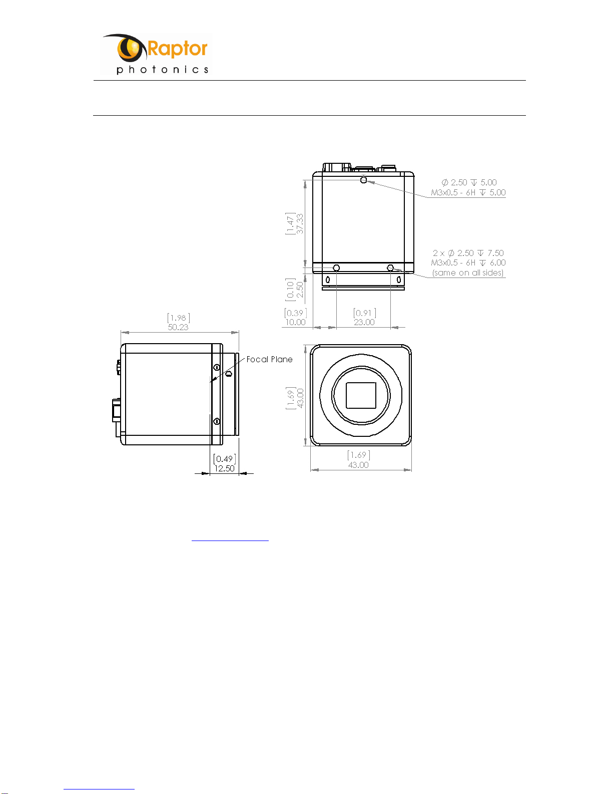
2.2 Mechanical Profile .................................................................................................................................... 7
3DESIGN DETAILS.............................................................................................. 8
3.1 Electrical Design....................................................................................................................................... 8
3.1.1 Power Input..................................................................................................................................... 8
3.1.2 Communications Interface............................................................................................................... 8
3.1.3 Trigger Output................................................................................................................................. 8
3.1.4 Analogue Video out......................................................................................................................... 8
3.1.5 Iris Control....................................................................................................................................... 9
3.2 Functionality.............................................................................................................................................. 9
3.2.1 Automatic Light Control (ALC)......................................................................................................... 9
4SERIAL COMMUNICATION (RS485) ...............................................................10
4.1 Overview..................................................................................................................................................10
4.2 ETX/Error Codes .....................................................................................................................................11
4.3 Set Commands........................................................................................................................................12
4.4 Query Commands....................................................................................................................................13
4.5 Examples.................................................................................................................................................14
4.5.1 Get System Status .........................................................................................................................14
4.5.2 Get Micro version...........................................................................................................................14
4.5.3 Read internal temperature..............................................................................................................14
4.5.4 Command acknowledge.................................................................................................................14
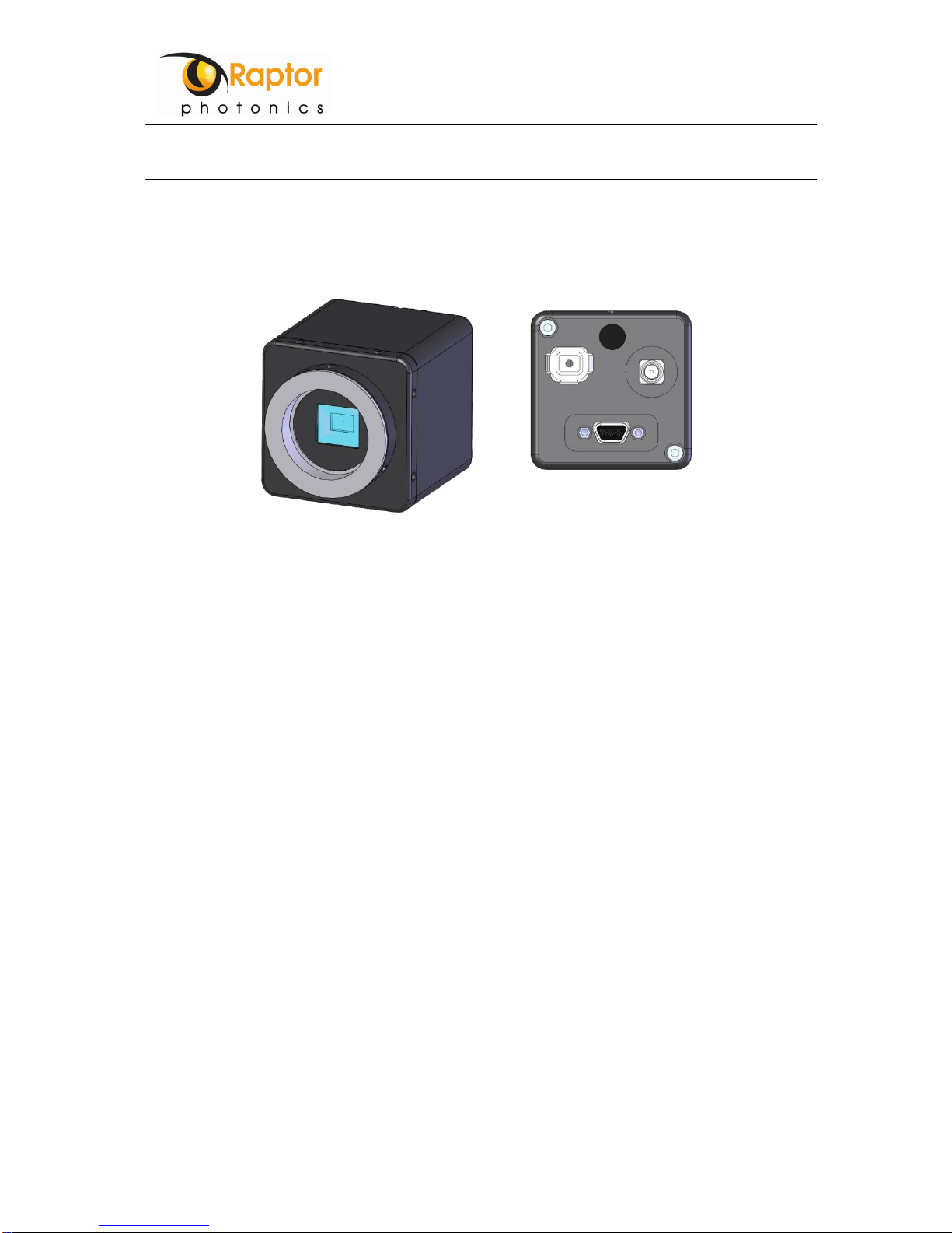
Figure 1: Mechanical profile drawing –SolidWorks model..................................................................................... 5
Figure 2: 9 Pin MDM connector............................................................................................................................... 6
Figure 3: Mechanical external dimensions.............................................................................................................. 7
Figure 4: Trigger Output HK829-AC........................................................................................................................ 8

Hawk Instruction Manual
Document number
Revision
File name
Date
Page
2015-07-22-05
V1.1
HK82x_IM_v1_1
30th Jul 2015
4 of 14
ACRONYMS
ALC
Automatic Light Control
CCD
Charge Coupled Device
EEPROM
Electrically Erasable Programmable Read Only Memory
FPGA
Field Programmable Gate Array
LSB
Least Significant Bit
MSB
Most Significant Bit
UART
Universal Asynchronous Receiver/Transmitter

Hawk Instruction Manual
Document number
Revision
File name
Date
Page
2015-07-22-05
V1.1
HK82x_IM_v1_1
30th Jul 2015
5 of 14
1 SCOPE
This document details the design for the Hawk 829 mono PAL, colour PAL & NTSC cameras (P/N: HK829-AP/
HK829-AC / HK247-AE). Details of the camera electrical interfaces and communication protocols are also
provided.
Figure 1: Mechanical profile drawing –SolidWorks model.

Hawk Instruction Manual
Document number
Revision
File name
Date
Page
2015-07-22-05
V1.1
HK82x_IM_v1_1
30th Jul 2015
6 of 14
2 DESIGN OVERVIEW
2.1 Physical Interfaces
2.1.1 Power, Trigger & Communications - 9 pin Micro-D socket (Glenair MDM-9SBSP)
The pin-out table is shown below (image seen from rear of camera).
The associated male connector part # is: MWDM2L-9P-xxx-xx.
Pin
I/O
Signal Name
Breakout Cable
(if applicable)
1
In/Out
RS485-A
Yellow
2
In/Out
RS485-B
Orange
3
In/Out
Trigger
Red
4
-
GND
Brown
5
In
+12V
Black
6
-
Reserved
Grey
7
-
Reserved
Violet
8
O
Reserved
Blue
9
-
GND
Green
Figure 2: 9 Pin MDM connector
2.1.2 Video Output - SMA
The camera has a 50Ω characteristic impedance SMA connector (Molex 73391-0070) on the rear panel for video
output. The internal circuit has a 75Ωsource impedance.
The pin-out table is shown below.
Pin
I/O
Signal Name
Inner
Out
Video
Outer
-
GROUND
Table 1: Video Connector Pinout
2.1.3 Iris Control - 4 pin socket
The iris connector (Kobi 163-158N-2-E) pin-out is shown in Table 2.
Pin
I/O
Signal Name
1
Out
+12V/ Damp-
2
Out
NC/Damp+
3
Out
Video/ Drive+
4
-
GROUND/ Drive-
Table 2: Iris connector pinout

Hawk Instruction Manual
Document number
Revision
File name
Date
Page
2015-07-22-05
V1.1
HK82x_IM_v1_1
30th Jul 2015
7 of 14
2.2 Mechanical Profile
Figure 3: Mechanical external dimensions
Notes:
-Drawing shown with CS mount ring fitted to camera
-CS-mount has a flange focal distance of 12.50mm.
-From the above drawing the estimated focal plane of the sensor can be found at 12.50mm from the front
of the CS ring.
-Note that the CS ring is adjustable to enable proper back focus of the camera.

Hawk Instruction Manual
Document number
Revision
File name
Date
Page
2015-07-22-05
V1.1
HK82x_IM_v1_1
30th Jul 2015
8 of 14
3 DESIGN DETAILS
3.1 Electrical Design
3.1.1 Power Input
The camera power specification is +12V +/- 10% and a maximum of 3.5W power dissipation.
3.1.2 Communications Interface
The RS485 communication interface has the specifications as listed in Table 3: RS485 Settings.
Baud rate:
115200 bps
Data bits:
8
Parity:
None
Stop bits:
1
Flow control:
None
Table 3: RS485 Settings
These settings are fixed and cannot be altered.
TIA/EIA-485A Standard Compliant, 120 Ωtermination.
3.1.3 Trigger Output
The trigger output has a 51Ω source impedance with a 3.3V pulse synchronised to the video out Vertical Sync
pulse, a HIGH indicates the first field and a LOW indicates the second field as shown in Figure 4.
.
Figure 4: Trigger Output HK829-AC
3.1.4 Analogue Video out
The camera is available with 3 video formats as detailed in Table 4.
Model
Part Number
Sensor
Resolution
Output
Hawk mono PAL
HK829-AC
752x582
CCIR 625 lines 50Hz field rate/ 25Hz frame rate
Hawk colour PAL
HK829-AP
752x582
PAL 625 lines 50Hz field rate/ 25Hz frame rate
Hawk mono NTSC
HK828-AE
768x494
EIA 525 lines 60Hz field rate/ 30Hz frame rate
Table 4: Camera Specifications

Hawk Instruction Manual
Document number
Revision
File name
Date
Page
2015-07-22-05
V1.1
HK82x_IM_v1_1
30th Jul 2015
9 of 14
Images are read from the Charge Coupled Device (CCD) sensor in progressive format, i.e. a complete is read
every 50/60Hz. Progressive to interlace conversion occurs within the camera firmware. The order of the odd/even
line combination is reversed for odd/even fields to preserve vertical resolution.
3.1.5 Iris Control
The camera Iris control circuit can be used with either a Video or DC lens. Further details of iris functionality are
provided in section 3.2.1.
3.2 Functionality
3.2.1 Automatic Light Control (ALC)
The ALC is enabled by default.
The ALC level is determined by an average across the whole image within a field.
Three modes of automatic light control exist:
1. Digital Gain: To achieve the set video level digital gain automatically adjusts the scaling on the internal
video signal. The set video level is compared with the average video in each video field to determine the
required digital gain to reach equilibrium. If ALC is disabled, digital gain remains fixed at the last level.
2. Auto EXP: Auto EXP will automatically adjust the internal Electronic Shutter to vary the effective
exposure of the CCD. The set video level is compared with the average video in each video field to
determine the required level of exposure to reach equilibrium. Note: Auto EXP only functions if ALC is
enabled. If ALC is disabled, exposure is fixed at the field period.
3. Auto Iris (Video and DC Iris lens modes): the camera has the capability to drive both Video Iris and DC
Iris lenses and can automatically detect which lens type is connected at power-up.
oVideo lens mode: the camera produces a separate iris video signal that is representative of the
image acquired by the CCD.
oDC lens mode: the camera produces a DC drive signal that is them inverse of the light level
acquired by the CCD, i.e. if the CCD light level is low the DC iris signal will be high to open the
iris.
Notes:
oIf ALC is disabled the exposure is fixed at 1 field period i.e. 20msecs and digital gain = 1.

Hawk Instruction Manual
Document number
Revision
File name
Date
Page
2015-07-22-05
V1.1
HK82x_IM_v1_1
30th Jul 2015
10 of 14
4 SERIAL COMMUNICATION (RS485)
4.1 Overview
For version 2.7 of the Micro firmware, the Power on default settings for camera serial port are;
-115200 baud
-1 start bit
-8 data bits
-1 stop bit
UART message format from Host to camera
Command
Data 1
Data 2
........
Data n
ETX
Chk_Sum
The first Byte is the command to the Microcontroller in the camera, following bytes contain data required by the
command, and the ETX byte terminates the command. 0x50 is always used to terminate the command. An
additional check sum byte may also be required to be sent by the host if check sum mode is enabled.
UART message format from camera to Host
Data 1
Data 2
........
Data n
ETX
Chk_Sum
All or none of the above bytes may be sent in response to commands from the host depending on the commands
sent by the host.
An optional mode of operation is included in the firmware for command acknowledge. Once enabled the camera
will respond to all commands send by the host. After the camera has received and processed the command from
the host, a single command acknowledge byte will be sent at the end of transmission (ETX) i.e. should the host
command require data to be sent from the camera then the ETX byte will be sent at the end of the requested
data.
Another optional mode of operation is included in the firmware is for check sum operation, this mode should only
be used when the command acknowledge mode is enabled. Once the check sum mode is enabled the camera
will only act upon commands that are received with the correct check sum byte sent at the end of the command
packet. Note that if the check sum feature is not enabled check sum bytes may still be sent at the end of a
command packet, the command will be processed and the check sum will be ignored. The check sum byte should
be the result of the Exclusive OR of all bytes in the Host command packet including the ETX byte.
When check sum mode is enabled data returned from the camera will include an echo of the checksum from the
host command
By default the camera will boot up with both command acknowledge and check sum operation disabled.
It is intended that the camera be operated from a higher level perspective whereby complete UART messages or
groups of UART messages are used to achieve required camera functionality.
Bits in registers that have not been identified in the documentation should be ignored.
Once a command has been received by the camera all sub sequent commands from the host will be ignored until
the command has been processed.

Hawk Instruction Manual
Document number
Revision
File name
Date
Page
2015-07-22-05
V1.1
HK82x_IM_v1_1
30th Jul 2015
11 of 14
4.2 ETX/Error Codes
Error codes will be sent as ETX characters by the camera in response to commands that have failed.
0x50
ETX
Command acknowledge, command processed successfully.
0x51
ETX_SER_TIMEOUT
Partial command packet received, camera timed out waiting for end of
packet. Command not processed
0x52
ETX_CK_SUM_ERR
Check sum transmitted by host did not match that calculated for the
packet. Command not processed
0x53
ETX_I2C_ERR
An I2C command has been received from the Host but failed internally
in the camera.
0x54
ETX_UNKNOWN_CMD
Data was detected on serial line, command not recognized
0x55
ETX_DONE_LOW
Host Command to access the camera EPROM successfully received
by camera but not processed as EPROM is busy. i.e. FPGA trying to
boot.

Hawk Instruction Manual
Document number
Revision
File name
Date
Page
2015-07-22-05
V1.1
HK82x_IM_v1_1
30th Jul 2015
12 of 14
4.3 Set Commands
Notes:
-Command 0x4F writes to the system status register, 0x49 reads from the system status register.
-Command 0x53 0xE0 write to the FPGA registers, 0x53 0xE1 read from the FPGA registers.
Set Command
Serial Packet
Comments
Set system state
0x4F 0xYY 0x50
Default = 0x16
YY Bit 6= 1 to enable check sum mode
YY Bit 4 = 1 to enable command ack
YY Bit 1 = 0 to Hold FPGA in RESET
YY Bit 0 = 1 to enable EEPROM communications
YY Bits 7,5,3,2 = reserved
Set FPGA CTRL
0x53 0xE0 0x02 0x00 0xYY 0x50
Default = 0x19
YY Bit 3 = 1 = to enable ALC (Default)
YY Bits 0-2,4-7 = unused
Set GAMMA / TEST
PATTERN
0x53 0xE0 0x02 0xFA 0xYY 0x50
Default = 0xE0
YY Bit 7 = 1 Gamma Enabled (Default)
Bit 3 Bit 2 Bit 1 Bit0 (of YY)
0 0 0 0 Disabled (Default)
0 0 1 0 Full White
0 0 1 1 ½ White
0 1 0 0 ¼ White
1 0 0 0 Black
1 0 0 1 Vertical Stripes
YY Bits 6,5,4 = unused

Hawk Instruction Manual
Document number
Revision
File name
Date
Page
2015-07-22-05
V1.1
HK82x_IM_v1_1
30th Jul 2015
13 of 14
4.4 Query Commands
Notes:
-Command 0x4F writes to the system status register, 0x49 reads from the system status register.
-Command 0x53 0xE0 write to the FPGA registers, 0x53 0xE1 read from the FPGA registers.
Query Command
Send Serial Packet
Comments
Get system status
0x49 0x50
1 Byte returned; Default = 0x16
YY Bit 6= 0 Check sum mode disabled
YY Bit 4 = 1 Command acknowledge enabled
YY Bit 1 = 1 FPGA enabled
YY Bit 0 = 0 EEPROM communications disabled
YY Bits 2,3,5,7 = reserved
Get FPGA CTRL
0x53 0xE0 0x01 0x00 0x50
0x53 0xE1 0x01 0x50
1 Byte returned; Default = 0x19
YY Bit 3 = 1 = to enable ALC (Default)
YY Bits 0-2,4-7 = unused
Get TEST PATTERN state
0x53 0xE0 0x01 0xFA 0x50
0x53 0xE1 0x01 0x50
1 byte returned; default = 0xE0
YY Bit 7= 1 Gamma Enabled (Default)
YY Bit 7= 0 Gamma Disabled
Bit 3 Bit 2 Bit 1 Bit0 (of YY)
0 0 0 0 Disabled (Default)
0 0 1 0 Full White
0 0 1 1 ½ White
0 1 0 0 ¼ White
1 0 0 0 Black
1 0 0 1 Vertical Stripes
Get internal temperature
0x53 0xE0 0x01 0x70 0x50
0x53 0xE1 0x01 0x50
0x53 0xE0 0x01 0x71 0x50
0x53 0xE1 0x01 0x50
2 bytes returned
1st byte = Top nibble (top 4 bits=0)
2nd byte = Lower byte
Counts = ((1st byte x 256)+2nd byte)
If counts<2048:
Positive Temperature oC=counts/16
If counts>2047:
Negative Temperature oC=(counts-4096)/16
Get Micro version
0x56 0x50
Two bytes transmitted from camera when command
received. 1st byte Major version 2nd byte Minor version.
Get FPGA version
0x53 0xE0 0x01 0x7E 0x50
0x53 0xE1 0x01 0x50
0x53 0xE0 0x01 0x7F 0x50
0x53 0xE1 0x01 0x50
Set address 7E (Major Version Byte)
Read address 7E, 1 byte
Set address 7F (Minor Version Byte)
Read address 7F, 1 byte
Get Unit Serial Number
0x4f 0x13 0x50
0x53 0xAE 0x05 0x01 0x00
0x00 0x02 0x00 0x50
0x53 0xAF 0x02 0x50
0x4f 0x12 0x50
Enable EEPROM access
2 bytes returned:
1st byte is the LSB
2nd is the MSB
Disable EEPROM access

Hawk Instruction Manual
Document number
Revision
File name
Date
Page
2015-07-22-05
V1.1
HK82x_IM_v1_1
30th Jul 2015
14 of 14
4.5 Examples
NOTE: an additional byte of 0x50 will be sent, by the camera, at the end of each command if cmd_ack is
enabled.
4.5.1 Get System Status
Command
TX bytes (to camera)
RX’d bytes (from camera)
Get system status
0x49 0x50
0x16
Checksum disabled, Command
Acknowledge enabled, FPGA
enabled, EEPROM
communications disabled
4.5.2 Get Micro version
Command
TX bytes (to camera)
RX’d bytes (from camera)
Get Micro version
0x56 0x50
0x02 0x07 (V2.7)
4.5.3 Read internal temperature
Command
TX bytes (to camera)
RX’d bytes (from camera)
Get internal temperature
0x53 0xE0 0x01 0x70 0x50
0x53 0xE1 0x01 0x50
0x53 0xE0 0x01 0x71 0x50
0x53 0xE1 0x01 0x50
0x02 0x64 = 612
Less than 2048 so positive. Divide
by 16:
612/16 = +38OC
4.5.4 Command acknowledge
Assume cmd ack = 0 to start
Command
TX bytes (to camera)
RX’d bytes (from camera)
Get system status
0x49 0x50
0x12
Binary OR status byte with 0x10
none
none
Enable Command Acknowledge
0x4F 0x16 0x50
0x50 (ack)
After ack is set
Command
TX bytes (to camera)
RX’d bytes (from camera)
Get Micro version
0x56 0x50
0x02 0x07 0x50 (v2.7+ack)
Table of contents
Other Raptor Photonics Digital Camera manuals

Raptor Photonics
Raptor Photonics OWL 640 S User manual

Raptor Photonics
Raptor Photonics OWL 640T User manual

Raptor Photonics
Raptor Photonics HAWK 252 User manual

Raptor Photonics
Raptor Photonics OWL 640 M User manual

Raptor Photonics
Raptor Photonics OWL 640 User manual

Raptor Photonics
Raptor Photonics Owl 640 II Series User manual

Raptor Photonics
Raptor Photonics OWL 1280 User manual

Raptor Photonics
Raptor Photonics Ninox 640 SU User manual