Raptor Photonics Ninox 640 SU User manual

NINOX 640 SU/USER MANUAL/01-21/REV1.0
NINOX 640 SU
Model: NXU-CL-640
USER MANUAL

NINOX 640 SU/USER MANUAL/01-21/REV1.0
CONTENTS
1. INTRODUCTION .............................................................................................................. 4
1.1 Scope ......................................................................................................................... 4
2. CAMERA CARE ............................................................................................................... 5
2.1 Cleaning the Sensor Window ................................................................................... 5
3. SPECIFICATION .............................................................................................................. 6
3.1 Camera Overview ...................................................................................................... 6
3.2 Datasheet ................................................................................................................... 6
4. DESIGN OVERVIEW ........................................................................................................ 7
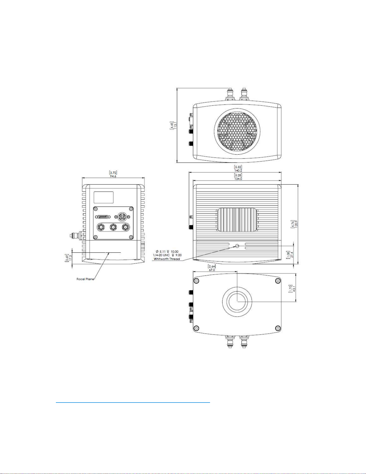
4.1 Mechanical Model ...................................................................................................... 7
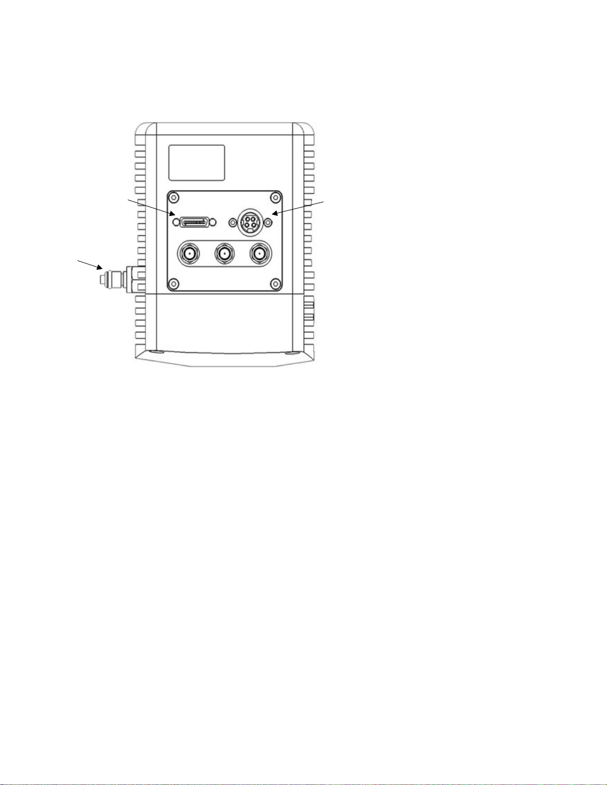
4.2 Physical Interface ...................................................................................................... 8
4.3 Power Consumption .................................................................................................. 8
4.4 Mounting to a Microscope ........................................................................................ 8
4.5 Mounting to a Tripod or Optical Table ..................................................................... 8
5. SOFTWARE COMPATIBILITY ......................................................................................... 9
5.1 XCAP Compatibility ................................................................................................... 9
5.2 LabView Compatibility .............................................................................................. 9
5.3 Custom Software Interfacing .................................................................................... 9
6. CAMERA AND CHILLER SETUP .................................................................................. 10
6.1 Connecting the Camera to the Frame Grabber ...................................................... 10
6.2 Connecting Camera to Chiller ................................................................................ 10
6.3 Recommended Coolants for Chiller ....................................................................... 10
6.4 Setting the Coolant Temperature for Re-circulation ............................................. 10
6.5 Draining the Chiller, Camera and Tubing ............................................................... 11
7. FRAME GRABBER AND SYSTEM REQUIREMENTS ................................................... 12
7.1 Computer/Laptop System Requirements ............................................................... 12
7.2 Frame Grabber Requirements ................................................................................ 12
8. XCAP IMAGING SOFTWARE ........................................................................................ 13
8.1 Downloading XCAP ................................................................................................. 13
8.2 Opening the Camera Configuration ....................................................................... 13
8.3 Acquiring a Live Image Sequence .......................................................................... 15
9. CONTROLLING THE CAMERA (XCAP) ........................................................................ 16
9.1 Exposure Time and Frame Rate ............................................................................. 16
9.2 Gain Mode ................................................................................................................ 17
9.3 Trigger Mode ............................................................................................................ 18
9.4 Thermoelectric Cooler (TEC) .................................................................................. 19

NINOX 640 SU/USER MANUAL/01-21/REV1.0
9.5 Manufacturers Data ................................................................................................. 20
10. XCAP CONTROL FEATURES ..................................................................................... 21
10.1 Saving Preset Configuration Settings .................................................................. 21
10.2 Contrast Modification (XCAP Std. Only) .............................................................. 22

NINOX 640 SU/USER MANUAL/01-21/REV1.0
1. INTRODUCTION
This document provides detailed instructions for the operation of the Ninox 640 SU camera.
Raptor Photonics Limited reserves the right to change this document at any time without
notice and disclaims liability for editorial, pictorial or typographical errors.
1.1 Scope
This manual covers the Ninox 640 SU digital camera and all applicable components. The
Ninox 640 SU is the lowest noise camera available. With an ultra-low typical readout noise
(rms) of 30e- and a typical dark current reading of <300e-/p/s at -80°C, the Ninox 640 SU
improves even further on its noise performance. Raptor recommends that this manual be
used to optimize camera operation. Details of the camera’s mechanical and electrical
interfaces are provided. Important precautions to be taken when using the camera are also
stated.
Detailed information is also provided on each of the cameras control parameters. Each
camera control is discussed and explained with the use of XCAP Imaging software, which is
the core plug and play software package that is offered with Raptor cameras. An image of
the camera is shown in Figure 1.
Figure 1: Complete Camera Module.

NINOX 640 SU/USER MANUAL/01-21/REV1.0
2. CAMERA CARE
2.1 Cleaning the Sensor Window
Raptor cameras require no regular maintenance except occasional external cleaning of the
sensor window (the glass window between the camera sensor and the microscope or lens).
Use optical grade isopropyl to clean this window. A cotton swab can be used, but may leave
some fibres on the window, so be careful. To avoid this, you could also use a lens tissue or a
cleaning swap such as a texwipe. Forced air can be applied to remove any loose particles.
Should any other issues occur please contact your local agent.
CAUTION — The camera’s sensor and circuits are sensitive to static discharge. Ensure that
you are using a static strap or completely grounded at all times to release any static energy
before you clean the window.
CAUTION — Do not use acetone.

NINOX 640 SU/USER MANUAL/01-21/REV1.0
3. SPECIFICATION
3.1 Camera Overview
The Ninox 640 SU is a 16-bit deep cooled SWIR camera. The camera has a response in the
SWIR region from 0.9µm to 1.7µm.
The Ninox 640 SU is an ultra-high sensitivity camera, offering a low dark current of <300 e/p/s
with a typical readout noise of 30e-. The camera has a high intra-scene dynamic range for
simultaneous capture of light and dark regions of a scene.
The Camera Link digital interface provides the most stable platform for data transfer and the
camera will work on any Camera Link standard frame grabber.
3.2 Datasheet
For the full specification of the Ninox 640 SU, the datasheet for the camera can be
downloaded from the Raptor Photonics website using the link below:
https://www.raptorphotonics.com/products/ninox-640-su/

NINOX 640 SU/USER MANUAL/01-21/REV1.0
4. DESIGN OVERVIEW
4.1 Mechanical Model
Units shown in mm and inches [in]
PDF of mechanical model available from our website:
https://www.raptorphotonics.com/products/ninox-640-su/

NINOX 640 SU/USER MANUAL/01-21/REV1.0
4.2 Physical Interface
4.3 Power Consumption
Unit input power specification is +12V +/- 0.5V with a maximum of 6W power dissipation with
the cooling fan switched on and the thermoelectric cooler (TEC) switched off. Additional
current is required when the TEC is enabled. The total maximum power dissipation is <110
Watts.
4.4 Mounting to a Microscope
The camera has a standard C-mount that should easily screw onto any microscope port.
4.5 Mounting to a Tripod or Optical Table
The camera has a ¼-20 BSW (Whitworth) threaded hole to mount to a tripod or an optical
table.
1. 3M CameraLink connector
Part #: 12226-1150-00FR
2. Power Connector
Part #: KPJX-PM-4S
3. Water Taps
Part #: CPC; MCD2402
4. SMA Connector: Trigger Out (Frame)
Single ended, termination
impedance = 51Ω, capable of sinking
and sourcing 32mA and will have an
output voltage of 3.3V i.e., TTL
compatible.
5. SMA Connector: Trigger In. Single
ended, termination impedance = 510
Ω, captive load = 200 pF, TTL
compatible.
6. SMA Connector: Trigger Out (Exp).
Single ended source impedance = 51
Ω, capable of sinking and sourcing
32mA and will have an output
voltage of 3.3V i.e,., TTL compatible.
2
3
4
5
1
6

NINOX 640 SU/USER MANUAL/01-21/REV1.0
5. SOFTWARE COMPATIBILITY
This section outlines the options relating to software that are available for the Ninox 640 SU.
5.1 XCAP Compatibility
Raptor works closely with EPIX who integrate all Raptor camera models into their XCAP
Imaging Software package. XCAP is the core plug and play software package that is offered
with the Ninox 640 SU.
5.2 LabView Compatibility
Raptor can supply a LabView .icd file which can be used to control the camera on National
Instruments imaging tools such as NI MAX. The file may also be useful if attempting to
create your own LabView VI.
5.3 Custom Software Interfacing
Raptor works closely with EPIX Inc, who integrates all Raptor cameras into their software
package, XCAP. The EPIX frame grabbers are the models that we offer with our cameras.
We offer their Software Development Kit (SDK) for interfacing with custom software (XCLIB).
If using a frame grabber from a different company, then you will have to obtain their SDK.
Raptor can provide an ICD which includes a list of all serial commands to control the
camera. This would be required along with the SDK from the frame grabber device to
integrate the camera.

NINOX 640 SU/USER MANUAL/01-21/REV1.0
6. CAMERA AND CHILLER SETUP
This section will give instruction on connecting the frame grabber to the camera, as well as
outlining important frame grabber and PC requirements.
6.1 Connecting the Camera to the Frame Grabber
The camera has the shrunk SDR port on the interface. The main frame grabber that Raptor offer
with this camera has the normal MDR port (EPIX EB1). Therefore, one MDR – SDR Camera Link
cable is required to connect the camera to this frame grabber.
If demoing the camera with the Mini PC system that Raptor provides, you should connect to
the left port of the frame grabber in the Mini PC. This should be stated on the Mini PC.
6.2 Connecting Camera to Chiller
Raptor uses a Chiller from Thermotek, the T257P Precision Chiller. For the datasheet and
full user manual from Thermotek, please contact Raptor and we can provide this. The
instructions to set up the chiller are as follows:
1. Connect the T257P chiller to the Ninox 640 SU using the tubing provided. You will hear a
click which indicates a solid connection. The polarity of the tubing connections does not
matter.
2. Keep the chiller horizontal and on a level surface.
3. Make sure there is a minimum 12” clearance and free path for flow of air entry and exit at
the left side and right side of the T257P chiller prior to operation.
4. Remove the reservoir cap and add coolant to the reservoir until the fluid reaches the
bottom of the neck. Please refer to section 6.3 for recommended coolants.
5. Close the cap securely to the reservoir. Make sure not to overfill the reservoir.
6. Install the appropriate end of the power cord into the unit and connect to the mains
electricity.
If using another chiller model, please refer to it’s manual for start-up instructions.
6.3 Recommended Coolants for Chiller
The recommended coolants are:
Option 1: Distilled Water
Option 2: 95% distilled water and 5% isopropyl alcohol mixture prevents bio growth.
Option 3: 80% distilled water and 20% inhibited Glycol mixture for set temperatures below
5C.
Raptor recommends using option 3. If purchasing the Thermotek model from Raptor or using
a demo kit provided by Raptor, there will be inhibited Glycol mixture provided to mix with
water.
6.4 Setting the Coolant Temperature for Re-circulation
When powering up the chiller, the screen will immediately give the option to set the
temperature of the coolant. It is recommended to set a 20 C set point. After the set

NINOX 640 SU/USER MANUAL/01-21/REV1.0
point has been configured, selecting start will initiate the coolant re-circulation. For
more detailed information on all the operating modes of the T257P Precision Chiller,
please refer to the Thermotek user manual.
WARNING: Please ensure the temperature set point of the chiller is above your ambient
dew point, otherwise condensation can form around the sensor package and cause
damage.
6.5 Draining the Chiller, Camera and Tubing
If using the Thermotek T257P Precision Chiller, it is recommended that a coolant
change be implemented at a minimum, every six months, to keep the system in working
order. Based on the amount of use, you may need to perform this more frequently. For more
detailed information, please refer to the Thermotek user manual. If using another model of
chiller, please refer to its user manual for the recommended time frame for coolant changes.
If finishing the testing of a demo kit, please disconnect the tubing and drain all of the camera,
chiller and tubing before sending the equipment back to Raptor. Shorter draining tubes will
be supplied with the demo kit. Two draining tubes (with the appropriate mating connectors)
need to be connected to both connecters on each of the camera, chiller and tubing to drain
each individually.

NINOX 640 SU/USER MANUAL/01-21/REV1.0
7. FRAME GRABBER AND SYSTEM REQUIREMENTS
7.1 Computer/Laptop System Requirements
The basic requirement is that the PCIe bus of the system must provide sufficient bandwidth
to handle video rate transfers. The amount of bandwidth required depends on the camera in-
hand. The Falcon III uses a Base Camera Link interface which can be handled with a x1
PCIe bus and PIXCI EB1, providing roughly 200MB/sec maximum bandwidth. Contact EPIX
Inc. for further information regarding minimum computer/laptop specification requirements to
run the XCAP Imaging Software.
7.2 Frame Grabber Requirements
If using a computer, it is a minimum requirement to use an PIXCI EB1 frame grabber. If
using a frame grabber from another company, the specification requirements of this frame
grabber must meet those supplied by the PIXCI EB1 model.
If using a laptop, EPIX offers base Camera Link frame grabbers for a laptop system, such as
the ECB1/ECB1-34.
.

NINOX 640 SU/USER MANUAL/01-21/REV1.0
8. XCAP IMAGING SOFTWARE
This section will discuss downloading and installing XCAP, as well as acquiring an image
using the software package.
8.1 Downloading XCAP
The latest version of XCAP can be downloaded from the link below:
http://www.epixinc.com/support/files.php
please select the appropriate version of XCAP for your computer. Ensure that you download
from the section labelled “Pre-release version with support for the latest cameras and
latest PIXCI® imaging boards”. Open the downloaded file when complete and follow the
onscreen instructions in the installation wizard. If a pop-up message appears asking whether
to install the PIXCI driver, ensure that you click yes.
8.2 Opening the Camera Configuration
After opening XCAP, select “PIXCI Open/Close” from the “PIXCI” tab from the top menu bar
in the main window. A PIXCI Open/Close pop-up box will open as shown in Figure 2.
Click on “Camera & Format” that is highlighted in Figure 2 and a “PIXCI Open Camera &
Format” box will appear, as shown in Figure 3.
Figure 2: PIXCI Open/Close.

NINOX 640 SU/USER MANUAL/01-21/REV1.0
Using the dropdown menu highlighted, search for “Raptor Photonics Ninox 640 SU”. You will
see the configuration for “Raptor Photonics Ninox 640 SU”. Selecting “Open w. Default
Video Setup” will open the control panel with all control parameters set to the default states.
“Open w. Last used Video Setup” will open the control panel with all parameters set at the
last known state. Once this option between the two has been selected, click “Ok”. To open
the camera control panel and imaging window, click “Open” in the “PIXCI Open/Close”
window (Figure 2).
Two windows will now open in XCAP, an imaging window and control panel, as shown in
Figure 4.
Figure 4: Imaging Window and Control Panel.
Figure 3: PIXCI Open Camera & Format.

NINOX 640 SU/USER MANUAL/01-21/REV1.0
8.3 Acquiring a Live Image Sequence
There are two things to observe in the control panel that inform you that the camera is
connected and ready to image.
The serial connect checkbox must be ticked in the control panel. This informs you that you
have established a serial connection with the camera and can control the camera.
Secondly, the symbol near the bottom right of the control panel will have three moving dots.
This indicates that you are obtaining video data from the camera. The imaging statistics
displayed directly underneath the imaging window will also inform you if you are receiving a
video feed from the camera.
Once you have established a serial connection with the camera and are receiving video
data, you can now grab a live image feed. Clicking the “Live” button will grab a live image
sequence which you will now see in the imaging window.
The symbols in the control app discussed above are displayed in Figure 5.
Figure 5: Checking Camera Connection and Acquiring a Live
Image.

NINOX 640 SU/USER MANUAL/01-21/REV1.0
9. CONTROLLING THE CAMERA (XCAP)
The sections below will give information on using each control of the Ninox 640 SU, giving a
description on how to use each control parameter and their effect on the camera’s
performance. The software used to illustrate the camera controls is XCAP.
9.1 Exposure Time and Frame Rate
The exposure time can be controlled under any camera control tab in the XCAP GUI and
remains constant on the GUI.
The minimum and maximum exposure times that the camera can set are shown in the table
below in Figure 6.
High Gain
Low Gain
Min. Exposure Time 15µs 15µs
Max.
Exposure Time
Frame Period
(ms)
–
10.2ms
Frame Period
(ms)
–
10.2ms
Exposure Resolution
13.89ns 13.89ns
Frame Rate: The frame rate can also be set using the frame rate user input box located
under the Trigger tab. By default, the frame rate is set to 25fps. The maximum frame rate of
the camera is 100fps. If an exposure time is selected that exceeds the exposure time limit of
the current frame rate set, then the exposure time will dominate, and the frame rate will be
decreased. Alternatively, if the user selects a frame rate that is too fast for the current
exposure time set, XCAP will decrease the exposure time.
Figure 7: Exposure Time & Frame Rate Controls.
Figure 6: Minimum and Maximum Exposure Times.

NINOX 640 SU/USER MANUAL/01-21/REV1.0
9.2 Gain Mode
The camera has two modes of operation, high gain mode and low gain mode (default). The
gain mode of the camera can be toggled from the “Gain” tab on the GUI.
High gain mode provides the best noise performance and can provide better images for low
scene illumination e.g. night imaging.
Low gain mode provides the best dynamic range and can provide better images for high
scene illumination e.g. daytime imaging or using large exposure times.
The gain mode control is shown in Figure 10.
Figure 10: Gain Mode Control.

NINOX 640 SU/USER MANUAL/01-21/REV1.0
9.3 Trigger Mode
The trigger mode of the camera and additional trigger controls can be controlled from the
“Trigger” tab in the GUI, shown in Figure 11.
The trigger mode of the camera can be toggled from the “Readout Mode” dropdown box. By
default, the camera will be set to internal trigger. This mode is indicated by the “Live” option
in the dropdown box.
The camera can be switched to external trigger mode by selecting the “Ext. Triggered”
option. When this mode is enabled, the “Trigger Polarity” (rising or falling edge) dropdown
input box will become available. By default, the camera will run with a rising edge trigger
polarity. A trigger delay can also be set when external trigger mode is enabled.
Figure 11: Trigger Mode.

NINOX 640 SU/USER MANUAL/01-21/REV1.0
9.4 Thermoelectric Cooler (TEC)
The Ninox 640 SU uses a TEC to cool the sensor temperature of -80 C. The TEC status is
shown in the “TEC” tab of the XCAP GUI, shown in Figure 13.
The TEC control can be enabled/disabled from this tab. By default, the TEC will be enabled
and set to a -80 C set point. Raptor recommends keeping the set point at this temperature,
as the camera is tested at this temperature under QC, and this is the specification TEC set
point of the camera.
To achieve a sensor temperature of -80 C, liquid cooling is required. For more information
on this, please refer to section 6.2. If the camera is in a room temperature environment, the
TEC set point of -50 C should be achievable using only the fan. By default, the fan is
enabled.
The sensor temperature can also be read back from this tab. Clicking “Update Temp.” will
read the current sensor temperature.
Figure 13: Thermoelectric Cooler (TEC) Control.

NINOX 640 SU/USER MANUAL/01-21/REV1.0
9.5 Manufacturers Data
The “Info” tab displays the manufacturers data of the camera, such as the firmware version
and serial number etc. The PCB and sensor temperature can be read back from this tab by
clicking “Update Temp.” The “Info” tab is shown in Figure 15.
Figure 15: Manufacturers Data.
This manual suits for next models
1
Table of contents
Other Raptor Photonics Digital Camera manuals

Raptor Photonics
Raptor Photonics OWL 640 User manual

Raptor Photonics
Raptor Photonics OWL 1280 User manual

Raptor Photonics
Raptor Photonics Hawk User manual

Raptor Photonics
Raptor Photonics OWL 640 S User manual

Raptor Photonics
Raptor Photonics Owl 640 II Series User manual

Raptor Photonics
Raptor Photonics HAWK 252 User manual

Raptor Photonics
Raptor Photonics OWL 640 M User manual

Raptor Photonics
Raptor Photonics OWL 640T User manual