Raptor Photonics NINOX 640 II User manual

NINOX 640 II/USER MANUAL/09-20/REV1.1
NINOX 640 II
Model: NN1.7-VS-CL-640
USER MANUAL

NINOX 640 II/USER MANUAL/09-20/REV1.1
CONTENTS
1. INTRODUCTION .............................................................................................................. 4
1.1 Scope .......................................................................................................................... 4
2. CAMERA CARE ............................................................................................................... 5
2.1 Cleaning the Sensor Window ....................................................................................... 5
3. SPECIFICATION .............................................................................................................. 6
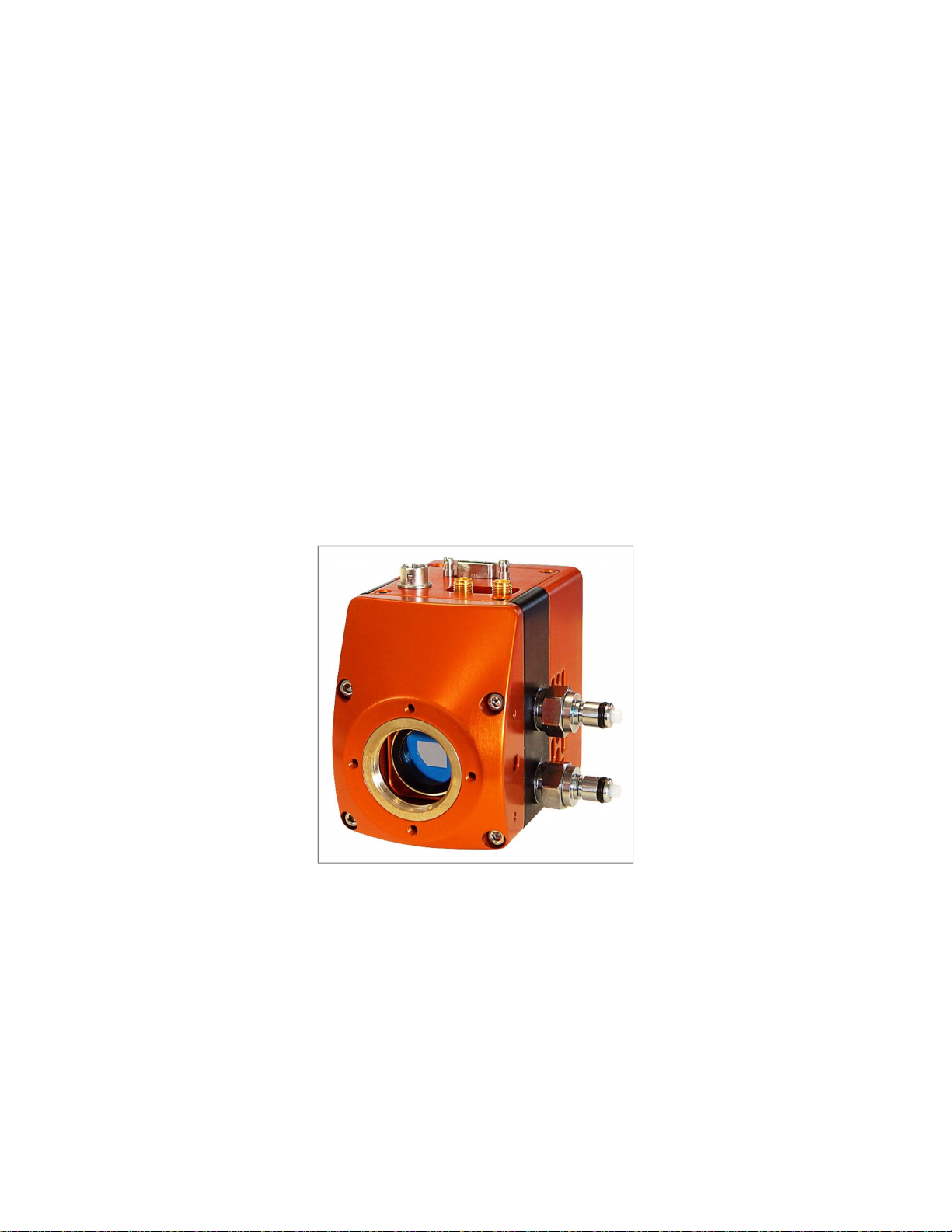
3.1 Camera Overview ........................................................................................................ 6
3.2 Datasheet .................................................................................................................... 6
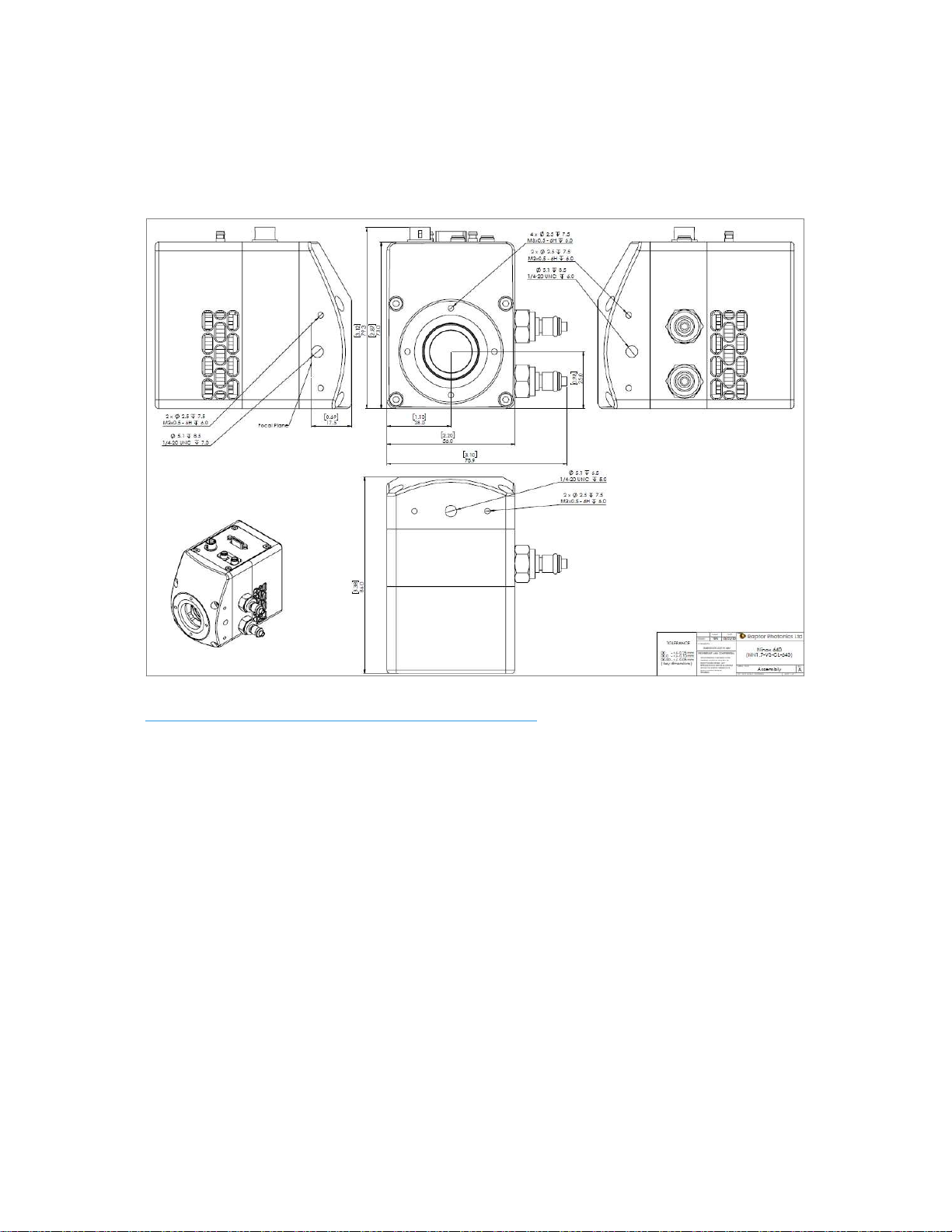
4. DESIGN OVERVIEW ........................................................................................................ 7
4.1 Mechanical Model ........................................................................................................ 7
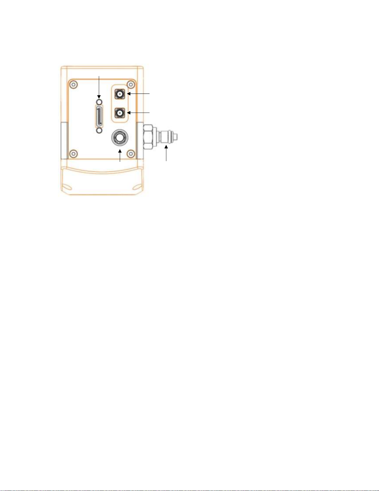
4.2 Physical Interface ........................................................................................................ 8
4.3 Power Consumption .................................................................................................... 8
4.4 Mounting to a Microscope ............................................................................................ 8
4.5 Mounting to a Tripod or Optical Table .......................................................................... 8
5. SOFTWARE COMPATIBILITY ......................................................................................... 9
5.1 XCAP Compatibility ..................................................................................................... 9
5.2 Micro-Manager Compatibility ....................................................................................... 9
5.3 LabView Compatibility ................................................................................................. 9
5.4 Custom Software Interfacing ........................................................................................ 9
6. CAMERA SETUP AND REQUIRMENTS ........................................................................ 10
6.1 Connecting the Camera to the Frame Grabber .......................................................... 10
6.2 Computer/Laptop System Requirements ................................................................... 10
6.3 Frame Grabber Requirements ................................................................................... 10
7. CHILLER SETUP & LIQUID COOLING (IF APPLICABLE) ............................................ 11
7.1 Liquid Cooling Requirement....................................................................................... 11
7.2 Connecting the Camera to the Chiller ........................................................................ 11
7.3 Recommended Coolants for the Chiller ..................................................................... 11
7.4 Setting the Coolant Temperature for Re-circulation ................................................... 12
7.5 Draining the Chiller, Camera and Tubing ................................................................... 12
7. XCAP IMAGING SOFTWARE ........................................................................................ 13
7.1 Downloading XCAP ................................................................................................... 13
7.2 Opening the Camera Configuration ........................................................................... 13
7.3 Acquiring a Live Image Sequence ............................................................................. 15
8. CONTROLLING THE CAMERA (XCAP) ........................................................................ 16
8.1 Exposure Time and Frame Rate ................................................................................ 16
8.2 Automatic Light Control Adjustment ........................................................................... 18

NINOX 640 II/USER MANUAL/09-20/REV1.1
8.2.1 Automatic Light Control Parameters ............................................................................. 18
8.2.2 Automatic Light Control Region of Interest................................................................... 19
8.2 Gain Mode ................................................................................................................. 20
8.3 Trigger Mode ............................................................................................................. 21
8.4 Non-Uniformity Correction (NUC) .............................................................................. 22
8.5 Thermoelectric Cooler (TEC) ..................................................................................... 23
8.6 Miscellaneous Tab ..................................................................................................... 24
8.7 Manufacturers Data ................................................................................................... 25
9. XCAP CONTROL FEATURES ....................................................................................... 26
9.1 Saving Preset Configuration Settings ........................................................................ 26
9.2 Contrast Modification (XCAP Std. Only) .................................................................... 27
10. MICRO-MANAGER ...................................................................................................... 28
10.1 Downloading and Installing Micro-Manager (Windows) ............................................ 28
10.2 Creating Camera Configuration File ......................................................................... 29
10.3 Pre-made Configuration File .................................................................................... 33
10.4 Imaging and Controlling the Camera ....................................................................... 34

NINOX 640 II/USER MANUAL/09-20/REV1.1
1. INTRODUCTION
This document provides detailed instructions for the operation of the Ninox 640 II camera.
Raptor Photonics Limited reserves the right to change this document at any time without
notice and disclaims liability for editorial, pictorial or typographical errors.
1.1 Scope
This manual covers the Ninox 640 II digital camera and all applicable components. The
Ninox 640 II is the next generation of the highly successful Ninox 640. With an ultra-low
typical readout noise (rms) of 18e- and a typical dark current reading of <1,500e-/p/s at -
15°C, the Ninox 640 II improves even further on its noise performance. The mechanical
design of the camera is also much improved and the camera is significantly more compact
than the initial Ninox 640. It is one of the most compact scientific SWIR cameras available on
the market. Raptor recommends that this manual be used to optimize camera operation.
Details of the camera’s mechanical and electrical interfaces are provided. Important
precautions to be taken when using the camera are also stated.
Detailed information is also provided on each of the cameras control parameters. Each
camera control is discussed and explained with the use of XCAP Imaging software, which is
the core plug and play software package that is offered with Raptor cameras. An image of
the camera is shown in Figure 1.
Figure 1: Complete Camera Module.

NINOX 640 II/USER MANUAL/09-20/REV1.1
2. CAMERA CARE
2.1 Cleaning the Sensor Window
Raptor cameras require no regular maintenance except occasional external cleaning of the
sensor window (the glass window between the camera sensor and the microscope or lens).
Use optical grade isopropyl to clean this window. A cotton swab can be used, but may leave
some fibres on the window, so be careful. To avoid this, you could also use a lens tissue or a
cleaning swap such as a texwipe. Forced air can be applied to remove any loose particles.
Should any other issues occur please contact your local agent.
CAUTION — The camera’s sensor and circuits are sensitive to static discharge. Ensure that
you are using a static strap or completely grounded at all times to release any static energy
before you clean the window.
CAUTION — Do not use acetone.

NINOX 640 II/USER MANUAL/09-20/REV1.1
3. SPECIFICATION
3.1 Camera Overview
The Ninox 640 II is the next generation of the Ninox 640, offering lower noise and smaller
mechanics. The camera has a response in the VIS-SWIR region from 0.4µm to 1.7µm.
The Ninox 640 II is a compact, rugged and high sensitivity camera. With a typical readout
noise of 18e-, the camera has a high intra-scene dynamic range for simultaneous capture of
light and dark regions of a scene.
The Camera Link digital interface provides the most stable platform for data transfer and the
camera will work on any Camera Link standard frame grabber.
3.2 Datasheet
For the full specification of the Ninox 640 II, the datasheet for the camera can be
downloaded from the Raptor Photonics website using the link below:
https://www.raptorphotonics.com/products/ninox-640-ii/

NINOX 640 II/USER MANUAL/09-20/REV1.1
4. DESIGN OVERVIEW
4.1 Mechanical Model
Units shown in mm and inches [in]
PDF of mechanical model available from our website:
https://www.raptorphotonics.com/products/ninox-640-ii/

NINOX 640 II/USER MANUAL/09-20/REV1.1
4.2 Physical Interface
4.3 Power Consumption
Unit input power specification is +12V +/- 0.5V with a maximum of 5W power dissipation
when the TEC is disabled. An additional 5W may be required if the full drive to the TEC is
required. This will be dependent on environmental conditions and the TEC temperature set
point. On power up, the peak power due to inrush current will be <12W.
4.4 Mounting to a Microscope
The camera has a standard C-mount that should easily screw onto any microscope port.
4.5 Mounting to a Tripod or Optical Table
The camera has a ¼-20 BSW (Whitworth) threaded hole to mount to a tripod or an optical
table.
1. 4 Pin Hirose Connector
2. SDR Camera Link Connector
3. SMA Connector: Trigger OUT
Single ended, source impedance =
51Ω, capable of sinking and
sourcing 32mA and will have an
output voltage of 3.3V i.e. TTL
compatible.
4. SMA Connector: Trigger IN
Single ended, termination
impedance = 510Ω, capacitive load
= 200pF [TTL compatible].
5. Liquid cooling IN/OUT valve
coupling (x2 IN/OUT)
1
2
3
4
5

NINOX 640 II/USER MANUAL/09-20/REV1.1
5. SOFTWARE COMPATIBILITY
This section outlines the options relating to software that are available for the Ninox 640 II.
5.1 XCAP Compatibility
Raptor works closely with EPIX who integrate all Raptor camera models into their XCAP
Imaging Software package. XCAP is the core plug and play software package that is offered
with the Ninox 640 II.
5.2 Micro-Manager Compatibility
The Ninox 640 II can be controlled and imaged using the free open source software
package, Micromanager. Using the camera with this software package is discussed in
section 10.
5.3 LabView Compatibility
Raptor can supply a LabView .icd file which can be used to control the camera on National
Instruments imaging tools such as NI MAX. The file may also be useful if attempting to
create your own LabView VI.
5.4 Custom Software Interfacing
Raptor works closely with EPIX Inc, who integrates all Raptor cameras into their software
package, XCAP. The EPIX frame grabbers are the models that we offer with our cameras.
We offer their Software Development Kit (SDK) for interfacing with custom software (XCLIB).
If using a frame grabber from a different company, then you will have to obtain their SDK.
Raptor can provide an ICD which includes a list of all serial commands to control the
camera. This would be required along with the SDK from the frame grabber device to
integrate the camera.

NINOX 640 II/USER MANUAL/09-20/REV1.1
6. CAMERA SETUP AND REQUIRMENTS
This section will give instruction on connecting the frame grabber to the camera, as well as
outlining important frame grabber and PC requirements.
6.1 Connecting the Camera to the Frame Grabber
The camera has the shrunk SDR port on the interface. The main frame grabber that Raptor
offer with this camera has the normal MDR port (EPIX EB1). Therefore, one MDR – SDR
Camera Link cable is required to connect the camera to this frame grabber.
If demoing the camera with the Mini PC system that Raptor provides, you should connect to
the left port of the frame grabber in the Mini PC. This should be stated on the Mini PC.
6.2 Computer/Laptop System Requirements
The basic system requirement is that the PCIe bus of the system must provide sufficient
bandwidth to handle video rate transfers. The amount of bandwidth required depends on the
camera in-hand. The Ninox 640 II uses a Base Camera Link interface which can be handled
with a x1 PCIe bus and PIXCI EB1 from EPIX, providing roughly 200MB/sec maximum
bandwidth. Contact EPIX Inc. for further information regarding minimum computer/laptop
specification requirements to run the XCAP Imaging Software.
6.3 Frame Grabber Requirements
If using a computer, it is a minimum requirement to use an PIXCI EB1 frame grabber. If
using a frame grabber from another company, the specification requirements of this frame
grabber must meet those supplied by the PIXCI EB1 model.
If using a laptop, EPIX offers base Camera Link frame grabbers for a laptop system, such as
the ECB1/ECB1-34.

NINOX 640 II/USER MANUAL/09-20/REV1.1
7. CHILLER SETUP & LIQUID COOLING (IF APPLICABLE)
This section discusses setting up the chiller if using the liquid cooling. The use of liquid
cooling is not essential with the camera. In most situations, the use of solely the fan should
be able to reach the sensor cooling spec of -15 C.
7.1 Liquid Cooling Requirement
There is a maximum delta of roughly 40 C between the PCB and sensor temperature.
Therefore, in situations where imaging in higher ambient temperatures, the PCB temperature
may rise too high for the TEC to be able to cool the sensor to -15 C. This is where liquid
cooling would be required, as liquid cooling dissipates heat away from the device more
effectively than the fan. The PCB temperature would therefore stay more stable at a lower
temperature, allowing the TEC to reach the -15 C set point.
7.2 Connecting the Camera to the Chiller
Raptor uses a chiller from Thermotek, the T257P Precision Chiller. If the Thermotek chiller
has been purchased from Raptor, the full chiller user manual will be included. Raptor
recommends referring to this manual for full instruction and precautions to take when using
the chiller. Raptor can also provide the T257P Precision Chiller datasheet and user manual if
required. The instructions to set up the chiller are as follows:
1. Connect the T257P chiller to the Falcon III using the tubing provided. You will hear a click
which indicates a solid connection. The polarity of the tubing connections does not matter.
2. Keep the chiller horizontal and on a level surface.
3. Make sure there is a minimum 12” clearance and free path for flow of air entry and exit at
the left side and right side of the T257P chiller prior to operation.
4. Remove the reservoir cap and add coolant to the reservoir until the fluid reaches the
bottom of the neck. Please refer to section 6.3 for recommended coolants.
5. Close the cap securely to the reservoir. Make sure not to overfill the reservoir.
6. Install the appropriate end of the power cord into the unit and connect to the mains
electricity.
If using another chiller model, please refer to it’s manual for start-up instructions.
7.3 Recommended Coolants for the Chiller
The recommended coolants are:
Option 1: Distilled Water
Option 2: 95% distilled water and 5% isopropyl alcohol mixture prevents bio growth.
Option 3: 80% distilled water and 20% inhibited Glycol mixture for set temperatures below
5 C.
Raptor recommends using option 3. If purchasing the Thermotek model from Raptor or using
a demo kit provided by Raptor, there will be inhibited Glycol mixture provided to mix with
water.

NINOX 640 II/USER MANUAL/09-20/REV1.1
7.4 Setting the Coolant Temperature for Re-circulation
When powering up the chiller, the screen will immediately give the option to set the
temperature of the coolant. It is recommended to set a 20 C set point. After the set point has
been configured, selecting start will initiate the coolant re-circulation. For more detailed
information on all the operating modes of the T257P Precision Chiller, please refer to the
Thermotek user manual.
WARNING: Please ensure the temperature set point of the chiller is above your
ambient dew point, otherwise condensation can form around the sensor package and
cause damage.
7.5 Draining the Chiller, Camera and Tubing
If using the Thermotek T257P Precision Chiller, it is recommended that a coolant change be
implemented at a minimum, every six months, to keep the system in working order. Based
on the amount of use, you may need to perform this more frequently. For more detailed
information, please refer to the Thermotek T257P Precision Chiller user manual. If using
another model of chiller, please refer to its user manual for the recommended time frame for
coolant changes.
If finishing the testing of a demo kit, please disconnect the tubing and drain the camera,
chiller and tubing before sending the equipment back to Raptor. Shorter draining tubes
should be supplied with the demo kit. Two draining tubes (with the appropriate mating
connectors) need to be connected to both connecters on each of the camera, chiller and
tubing to drain each individually. If there are no draining tubes, both liquid connectors on
each component need to be pressed simultaneously in order for the liquid to drain.

NINOX 640 II/USER MANUAL/09-20/REV1.1
7. XCAP IMAGING SOFTWARE
This section will discuss downloading and acquiring an image using XCAP.
7.1 Downloading XCAP
The latest version of XCAP can be downloaded from the link below:
http://www.epixinc.com/support/files.php
please select the appropriate version of XCAP for your computer. Ensure that you download
from the section labelled “Pre-release version with support for the latest cameras and
latest PIXCI® imaging boards”. Open the downloaded file when complete and follow the
onscreen instructions in the installation wizard. If a pop-up message appears asking whether
to install the PIXCI driver, ensure that you click yes.
7.2 Opening the Camera Configuration
After opening XCAP, select “PIXCI Open/Close” from the “PIXCI” tab from the top menu bar
in the main window. A PIXCI Open/Close pop-up box will open as shown in Figure 2.
Click on “Camera & Format” that is highlighted in Figure 2 and a “PIXCI Open Camera &
Format” box will appear, as shown in Figure 3.
Figure 2: PIXCI Open/Close.
Figure 3: PIXCI Open Camera & Format.

NINOX 640 II/USER MANUAL/09-20/REV1.1
Using the dropdown menu highlighted, search for “Ninox 640 II”. You will see the
configuration for “Raptor Photonics Ninox 640 II”. Selecting “Open w. Default Video Setup”
will open the control panel with all control parameters set to the default states. “Open w. Last
used Video Setup” will open the control panel with all parameters set at the last known state.
Once this option between the two has been selected, click “Ok”. To open the camera control
panel and imaging window, click “Open” in the “PIXCI Open/Close” window (Figure 2).
Two windows will now open in XCAP, an imaging window and control panel, as shown in
Figure 4.
Figure 4: Imaging Window and Control Panel.

NINOX 640 II/USER MANUAL/09-20/REV1.1
7.3 Acquiring a Live Image Sequence
There are two things to observe in the control panel that inform you that the camera is
connected and ready to image.
The serial connect checkbox must be ticked in the control panel. This informs you that you
have established a serial connection with the camera and can control the camera.
Secondly, the symbol near the bottom right of the control panel will have three moving dots.
This indicates that you are obtaining video data from the camera. The imaging statistics
displayed directly underneath the imaging window will also inform you if you are receiving a
video feed from the camera.
Once you have established a serial connection with the camera and are receiving video
data, you can now grab a live image feed. Clicking the “Live” button will grab a live image
sequence which you will now see in the imaging window.
The symbols in the control app discussed above are displayed in Figure 5.
Figure 5: Checking Camera Connection and Acquiring a Live
Image.

NINOX 640 II/USER MANUAL/09-20/REV1.1
8. CONTROLLING THE CAMERA (XCAP)
The sections below will give information on using each control of the Ninox 640 II, giving a
description on how to use each control parameter and their effect on the camera’s
performance. The software used to illustrate the camera controls is XCAP.
8.1 Exposure Time and Frame Rate
The exposure time and frame rate can be controlled under any camera control tab in the
XCAP GUI and remains constant on the GUI.
Exposure Time: By default, the auto exposure control (ALC) will be enabled, meaning that
the exposure time and digital gain cannot be manually selected. The ALC will automatically
adjust these parameters based on the signal strength. The ALC can be fine tuned in multiple
ways. These controls are discussed in section 8.2.
If the ALC is disabled, the user will be able to set a fixed exposure time and digital gain,
using either the manual input box or the slider bar. The maximum exposure time that the
camera can perform is ~26.8s. However in practice, with the sensor only cooled to -15 C,
the image would display a lot of dark noise at this exposure time. In practice, the maximum
useable exposure time is probably closer to ~5s. Regardless, the limit on the exposure bar
slider on XCAP is 26800ms. An exposure time can be set either using the user input box or
the slider.
The minimum and maximum exposure times that the camera can set are shown in the table
below in Figure 6.
High Gain Low Gain
Min. Exposure Time
450
µs
50
µs
Max. Exposure Time
Frame Period
–
Readout Time
Frame Period
–
Readout Time
Maximum possible exposure time that the camera can perform is
~
26.8s.
Frame Rate: The frame rate can also be set using the frame rate user input box. By default,
the frame rate is set to 60fps. If an exposure time is selected that exceeds the exposure time
limit of the current frame rate set, then the exposure time will dominate, and the frame rate
will be decreased. Alternatively, if the user selects a frame rate that is too fast for the current
exposure time set, XCAP will decrease the exposure time.
Frame Rate and Maximum Exposure Time: The maximum exposure time is a function of
the frame period (1/frame rate) and the readout time. The relationship between these three
parameters is shown below:
𝑀𝑎𝑥𝑖𝑚𝑢𝑚 𝐸𝑥𝑝𝑜𝑠𝑢𝑟𝑒 𝑇𝑖𝑚𝑒 = 𝐹𝑟𝑎𝑚𝑒 𝑃𝑒𝑟𝑖𝑜𝑑 − 𝑅𝑒𝑎𝑑𝑜𝑢𝑡 𝑇𝑖𝑚𝑒
The readout time for the Ninox 640 II is dependent on whether the camera is in low (LG) or
high (HG) gain. The readout times for each gain mode are as follows:
Readout Time (LG) = ~6ms
Readout Time (HG) = ~10ms
Figure 6: Minimum and Maximum Exposure Times.

NINOX 640 II/USER MANUAL/09-20/REV1.1
When using an example of a frame rate of 25fps in low gain, the maximum exposure time
possible at this frame rate would be:
𝑀𝑎𝑥𝑖𝑚𝑢𝑚 𝐸𝑥𝑝𝑜𝑠𝑢𝑟𝑒 𝑇𝑖𝑚𝑒 = 1
25−(6×10)
= 34𝑚𝑠
The exposure time and frame rate controls on XCAP are shown in Figure 7.
Figure 7: ALC and Manual Exposure Time Controls.

NINOX 640 II/USER MANUAL/09-20/REV1.1
8.2 Automatic Light Control Adjustment
The ALC can be fine-tuned by adjusting a few different parameters. A Region of Interest
(ROI) of pixels can also be defined in which to drive the ALC. These controls are discussed
below.
8.2.1 Automatic Light Control Parameters
Peak and average video levels are derived and monitored for the active ROI and are used to
drive the ALC. The active video level used to compare to the set point can be adjusted from
full average to full peak or a percentage of both. The percentage used of the average and
peak video levels can be adjusted from the “Auto” tab in the XCAP GUI. An explanation of
the average and peak video levels is stated below.
Average Video Level: An average video level is calculated for the active ROI. This value
will be calculated in real time, i.e. as pixel data in the ROI is captured from the sensor, it is
fed directly to an accumulator. At the end of the frame, the accumulator is divided to give a
true average.
Peak Video Level: The peak video is determined from a rolling average of 4 pixels. Current
pixel + 3 previous pixels are used to derive a peak value. This peak value is monitored for
the ROI and latched at the end of frame.
Selecting a greater percentage from the average will drive the ALC to use greater exposure
and digital gain values. Selecting a greater percentage from the peak will have the opposite
effect.
ALC Level: The ALC level can also be adjusted to fine tune the ALC. Increasing the level
will cause greater exposure and digital gain values to be set by the ALC. Decreasing the
level will have the opposite effect.
Both controls can be adjusted to optimise the ALC for the current imaging scene conditions.
Figure 8: ALC Parameters.

NINOX 640 II/USER MANUAL/09-20/REV1.1
8.2.2 Automatic Light Control Region of Interest
A Region of Interest (ROI) within the main active region of 640 x 512 may be defined. This
region is used to calculate peak and average video levels to drive the Automatic Light
Control (ALC) function of the camera (discussed in section 8.3.1).
The ROI offset and sizes are outlined in Figure 9.
The active ROI for the ALC can be adjusted from the “Auto ROI” tab in the XCAP GUI,
shown in Figure 10.
The ROI can be moved to within a resolution of 4 pixels in the X and Y, and the ROI size will
have a resolution of 4 pixels.
An optional ROI outline feature can be enabled that highlights a 1 pixel wide box around the
active ROI set. This can be enabled by selecting “ROI Box” from the “ROI Highlight”
dropdown box. If the ROI highlight box is enabled or disabled, all pixels will have a gain of
1x.
If “ROI Contrast” is enabled, all pixels outside of the ROI selected will have a gain of 0.75x.
Figure 9: Region of Interest Size and Offset.

NINOX 640 II/USER MANUAL/09-20/REV1.1
8.2 Gain Mode
The camera has two modes of operation, high gain mode and low gain mode (default). The
gain mode of the camera can be toggled from the “Gain” tab on the GUI.
High gain mode provides the best noise performance and can provide better images for low
scene illumination e.g. night imaging.
Low gain mode provides the best dynamic range and can provide better images for high
scene illumination e.g. daytime imaging or using large exposure times.
The gain mode control is shown in Figure 10.
Figure 10: Gain Mode Control.
This manual suits for next models
1
Table of contents
Other Raptor Photonics Security Camera manuals