Raptor R00190 User manual

R00190
Wolseley UK, CV31 3HH
0344 292 7060
help@raptortool.co.uk
www.raptortool.co.uk
Before using the instrument, please read this manual
carefully and save for future reference.

Safety information
LASER RADIATION. Do not stare into
beam. Class 2 laser product. Turn the
laser beam on only when using this tool.
1 2
1. Do not remove or deface the product
labels.
2. Avoid direct eye exposure. The laser
beam can cause flash blindness.
3. Do not operate the tool around
children or allow children to operate
the tool.
4. Do not place the tool in a position
that may cause anyone to stare at the
laser beam, whether intentionally or
unintentionally.
5. Do not use on surfaces such as sheet
steel that have shiny, reflective
surfaces. The shiny surface could
reflect the beam back at the operator.

6. Always turn the laser tool off when
not in use. Leaving the tool on
increases the risk of someone
inadvertently staring into the
laser beam.
7. Do not attempt to modify the
performance of this laser device in
any way. This may result in a
dangerous exposure to the
laser radiation.
8. Do not attempt to repair or
disassemble the laser measuring
tool. If an unqualified person
attempts to repair this product,
serious injury may occur. Any repair
required on this laser product should
be performed only by qualified
service personnel.
2
Safety information

3 4
Safety Information.
Please read the User Manual before operating
the instrument
Important notices against hazards.
Compliant with EU legal requirements.
Warning!
Laser must be prevented from aligning itself
towards human eyes or reflective surfaces.
WEEE Directive 2012/19/EU At the end of
the product life, dispose of the instrument
& batteries in a corresponding recycling
centre. Do not dispose of the unit with the
usual domestic refuse.
Do not burn the product.
Safety information
LASER RADIATION
DO NOT STARE INTO BEAM
CLASS 2 LASER PRODUCT
Wavelength: 630-660nm Output of laser radiation: < 1mW
IEC/EN 60825-1:2014
• Safety Symbols
Beam Divergence: 1mrad
Protection is based on exposure being limited
by the natural aversion response (0.25secs)

4
Maintenance Information.
• Use a dry, clean cloth to clean the instrument.
Do not use solvents.
• For extra protection, always store the
instrument in the case provided when not
in use.
Important Information.
• If there is a sudden change in the
environmental temperature, the instrument
should be acclimatised for a minimum of
30 minutes. This will ensure the ambient
temperature is the same, both inside &
outside of the Thermometer
• The electromagnetic field from electric
welding and inductive heating must be
minimized.
• Do not place the Thermometer near to
hot objects
• The meter must be kept clean so that dust
is denied access to the lens cone.
Maintenance /
Important information
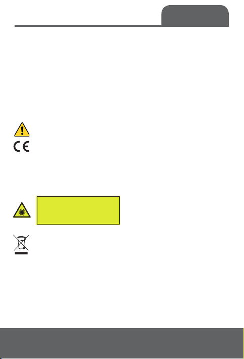
This instrument complies with the standards
provided below:
EN61326-1 EN60825-1 EN62471

Features
5 6
Physical Appearance.
1.
2.
3.
4.
5.
6.
7.
8.
9.
10.
11.
LED Green / Red alarm indicator
Colour LCD screen
Laser control key / numeric adjustment key
Mode key
UV light control key / numeric adjustment key
Infrared sensor’s sensing area
Laser aperture
UV light
K Type Thermocouple socket
Measure trigger
Battery cover
Height - 163mm
Width - 48mm
Length - 105mm
Weight - 310g
K-TYPE

6
LCD Screen.
1.
2.
3.
4.
5.
6.
7.
8.
9.
Primary display panel: displays measured
temperature.
Functional indication: displays Max PRb (K Type
probe), HAL (high LED alarm level), LAL (low
LED alarm level), E (emissivity) (adjust the
instruments emissivity).
Secondary display panel
Fahrenheit unit
Celsius unit
Low battery indicator
Temperature measurement indication
Data hold function
Laser enabling indication
Features

Measurement
Method
7 8
Measurement Method.
Setting the HAL (high) LAL (low) alarm.
1. Pull trigger and press mode key once, then
release trigger. This will show HAL (fig.1). Use
the left and right buttons / to set the
required HAL level LED alarm.
Example: Set the HAL to 30°C, when
temperature readings are being taken, the LED
above the screen will indicate green - until
the temperature reaches 30.1°C, it will then
indicate Red LED. (high alarm).
2. Once HAL values are set, press the mode button
one more time & this will show LAL (fig.2).
Use the left & right buttons / to set the
required LAL level LED alarm.
Fig.1

Measurement
Method
8
Example: Set the LAL to -10°C when temperature
readings are being taken. The LED above the
screen will show green until the temperature
reaches -10.1°C, it will then indicate red LED
(low alarm).
If you then pull the trigger for 2 seconds, the
instrument is ready for use.
The IR thermometer will stay at the set values
until the power is disconnected or battery
depleted. The default temperature value from
set up / battery replacement is 5°C / 41°F in HAL
and -5°C / 23°F in LAL.
Fig.2

Measurement
Method
9 10
Setting the emissivity
3. To set the emissivity, pull the trigger and
press mode twice. Pull trigger once, the
display shows E. Press mode once, the
display shows (fig.3). The emissivity can now
be set (see values on page 17/18).
Press mode once - shows E - the emissivity is
now set.
Pull the trigger to start taking temperatures.
The value will remain, until the power is
disconnected or battery depleted. The default
value from set up / battery replacement is 0.95.
Setting the Celsius & Fahrenheit
4. To set the temperature °C/°F on the
thermometer, press the Mode key for 2 seconds.
This will switch to the required °C/°F on the
right hand side of the LCD screen (fig.4/5).
Fig.3

Measurement
Method
10
Setting the Celsius & Fahrenheit
4. To set the temperature °C/°F on the
thermometer, press the Mode key for 2 seconds.
This will switch to the required °C/°F on the
right hand side of the LCD screen (fig.4/5).
Enabling the Laser
5.Enable / disable laser. Press key to
enable or disable laser. The instrument will
display the symbol for laser (fig.4)
Switching on the UV function
6. Turn on / off the UV light by pressing .
Leak detection: Leaks within domestic &
commercial air conditioning systems, or other
high pressure systems can be detected
quickly by ultraviolet. Fluorescent agent is
injected into the air conditioning system &
circulated, when the air conditioning system
has a leak, fluorescence leakage under the
irradiation of ultraviolet light can help
identify the leak.
Fig.4 Fig.5

Measurement
Method
11 12
Non-contact temperature measurement
7. Target the IR thermometer at an object
and pull the trigger. Hold the trigger to take
continuous measurement of temperature.
After display becomes stable, release the
trigger this will hold measurement results.
This is indicated on screen by (fig.6 point 8).
Having the Laser pointer enabled will help
position the laser more accurately.
Fig.6
K-TYPE

Measurement
Method
12
When the trigger is pressed, the instrument’s
secondary display panel (fig.7/8) will first
show the set emissivity and then display the
maximum measured temperature.
Attaching a K Type probe
8. A K Type Thermocouple / probe can be
attached via the K Type socket (fig.9)
(K Type Thermocouple supplied only).
Insert the K Type Thermocouple / probe into
the K Type socket (see fig.9) next page.
Ensure the legs of the plug are inserted into
the correct +/- socket; (+) narrow leg and
(-) wide leg. Once plugged in, the LCD
screen will show PRb (fig.10) and its
temperature reading bottom right (fig.10).
Fig.7 Fig.8

Measurement
method
13 14
Fig.9
Fig.10
K-TYPE

14
Proportion between the distance from the
instrument to an object and the diameter of
the object to be measured (D:S)
The IR Thermometer has a certain angle and
field of vision, as shown in the diagram below:
It must be ensured that the object to be
measured is fully within the field of vision
afforded by the IR Thermometer, that is, the
laser ring can see nothing but the object to
be measured. The greater the object to be
measured, the further the distance between the
object & thermometer must be. The smaller the
object is, the shorter the distance between the
object & thermometer must be. The proportion
between the distance to be measured and the
size of the object to be measured (D:S) is 12:1, as
shown on next page (fig.11).
Distance to Spot
Ratio (D:S)
The object to be
measured
Lens
Photosensitive element

15 16
While measuring an object, the instrument
will emit an indicative ring. The measured
temperature of the surface is the internal
temperature of the ring.
The indicative ring
should not exceed the
size of the object.
X
✓
Distance to Spot
Ratio (D:S)
Fig.11
K-TYPE

Emissivity
16
Emissivity
Emissivity refers to the ability of an object
to emit infrared ray. The greater the emissivity
is, the stronger the emission ability of the
surface of an object is.
The emissivity of most organic substances or
oxidized surfaces of metals falls within the
range of 0.85 0.98. The default emissivity of
this measurement device is 0.95.
The instrument’s emissivity is set to be
consistent with that of the object to be
measured at the moment of measurement
result must be noticed at the time of
measurement.

Emissivity
Reference Table
17 18

18
Emissivity
Reference Table

19 20
Battery.
When the battery power is low (top right),
The battery symbol indicator will show
at the (top right) on the LCD screen
(page 11, fig.6 point 6).
At such moment you must replace the existing
battery. Open the battery cover and replace
the old battery with a new 9V battery.
Refer to the diagram below:
Battery
Replacement
Note:
All set values
in HAL-LAL &
Emissivity will
return to the
default readings.
HAL +5°C/41°F
LAL -5°C/23°F
E - 0.95
*9V 6F22 Battery
(included)
K-TYPE
Other manuals for R00190
1
Table of contents
Other Raptor Thermometer manuals