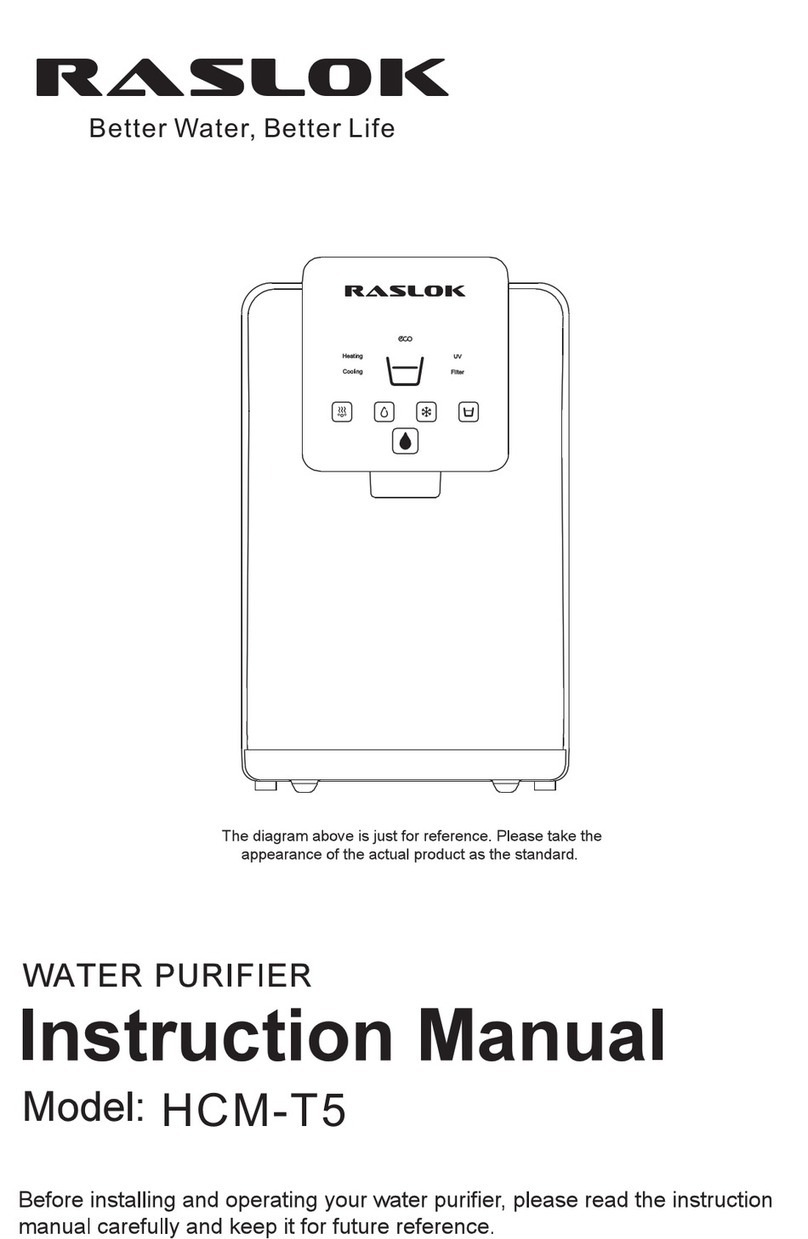
RASLOK HCM-T1 User manual

Page 1of 18
RASLOK
Better Water, Better Life
Operating Instructions
RASLOKTM Water Purifier
Model: HCM-T1
© 2012 RASLOK Pte. Ltd. All rights reserved.
RASLOK™ is a trademark of RASLOK Pte. Ltd., Singapore.
Website: www.raslok.com Email: sales@raslok.com
●
Design and color may differ from the picture.
●
Unit appearance, specification, etc. are subject to change without prior notice if necessary for improving unit performance.
●
The rated voltage of this unit is AC 220V/50Hz only.

Page 2of 18
Table of Contents
Safety Information....................................................................................... 3
NOTICE ................................................................................................... 4
Product Description (General Overview)
............................................................. 5
Touch Panel (Operation User Interface)........................................................... 6
Description of Button Operation ..................................................................... 8
System Settings.......................................................................................... 9
Diagrams of Machine’s internal workings
.......................................................... 13
Troubleshooting guide ................................................................................ 16
Technical specifications
................................................................................ 17
Warranty
.................................................................................................. 18

Page 3of 18
Safety Information
Read, understand, and follow all safety information contained in these instructions prior to
use of the RASLOK Water Purifier HCM-T1.
Retain these instructions for future reference.
Intended Use:
The RASLOK
TM
Water Purifier HCM-T1 is intended for use in filtering tap water for drinking purposes. The system
is typically installed at point of use and must be installed by a RASLOK authorized professional installer
according to installation instructions.
Explanation of Signal Word Consequences:
WARNING
Indicates a potentially hazardous situation, which, if not avoided,
could result in death or serious injury and/or property damage.
NOTICE
Indicates a situation which, if not avoided, could result in property
damage.
WARNINGS
About the Power Supply
To reduce the risks associated with hazardous voltage and fire:
●
Do not plug-in multiple devices into the same power outlet or extension cord simultaneously.
●
Plug the power cord into a 220 V outlet with at least a rating of 10 A and power surge protection.
●
Please ensure the power plug and power outlet is clean and dry.
●
Damaged parts or machine malfunction are only to be repaired or replaced by RASLOK
authorized professionals.
To reduce the risks associated with hazardous voltage:
●
Do not operate the machine with wet hands.
●
Do not bend the power cord excessively or put heavy objects over the power cord. Ensure your pets do
not damage the power cord.
●
Do not use the equipment if there is any damage to power cord, plug or the outlet.

Page 4of 18
Important guide during installation / Use
To reduce the risks associated with fire and explosion:
●
Do not place the equipment in area with potential gas leak, or near heating devices.
●
Do not put candles, lit cigarettes, or any heating devices on the unit.
To reduce the risks associated with hazardous voltage, fire and/or property damage:
●
Do not put water containers, chemicals (volatile materials, organic solvents etc.), small metal objects etc. on top of
unit to avoid accidental spillage into the unit to cause electric shock or fire.
To reduce the risks associated with fire and/or property damage:
●
Do not place the equipment in an enclosed space where ventilation is difficult, causing overheating
atthe
electricalparts.
To reduce the risks associated with contaminated water and/or property damage:
●
Do not clean the equipment with chemicals that could contaminate the water.
NOTICE
●
Do not install in direct sunlight or outdoors exposed to rain /snow. The equipment is designed for indoor
use only. Large amount of moisture or dust in the equipment surroundings may damage the equipment.
●
Do not tilt the equipment over 45° when transporting the unit. Install and keep the equipment on a flat
stable surface. Unstable surface and inclination will cause performance degradation or equipment
malfunction.
●
Do not connect to hot water source over 40 °C.
●
Keep equipment approximately 10 cm away from the wall and ensure proper ventilation behind the
equipment.
●
Ensure tubing are securely connected and is not bent or pressed down by any heavy objects.
●
The disposable filter cartridge must be replaced every 12 months, or if any noticeable reduction in flow
rate occurs (whichever sooner), to ensure filter effectiveness.
●
Ensure the product is connected to water mains by a detachable tubing hose. When you relocate and
reinstall the appliance, please use a new tubing hose.
●
This appliance is intended to be used indoors.
●
Close supervision is required when any appliance is used by or near children.
Safety Information

Page 5of 18
Product Description (General Overview)
1. User Interface/UI
2. Decorative plate
3. Waterspout
4. Front Panel
5. Top Cover
6. Drip Collector
7. Control Panel
8. Side Panel
9. Black Panel
10. Power Cord
11. Water Inlet
12. Heating System Switch
13. 1st Filter (Sediment & Carbon
Composite)
14. 2nd Filter (UF&ACF Composite)

Page 6of 18
Touch Panel (Operation User Interface)
Description of button functions
1). - Hot Water Dispensing Button (Red & White lights); used to start dispensing
of Hot water.
* light will turn red when the machine is heating and turn back white when
heating is finished.
* light will remain red during dispensing of hot water. Press any Button to
stop dispensing.
2). -Clock/Timer (White light): used to display time and settings data.
3). - Cold Water Dispensing Button (Blue & White lights); used to start
dispensing of Cold water.
* light will turn blue when the machine is cooling and turn back white when

Page 7of 18
cooling is finished.
* light will remain blue during dispensing of cold water. Press any Button to
stop dispensing.
4). - Volume selection Button (White light); used to select volume of water
dispensed from one of 3 values: 180ml, 220ml, or 1000ml.
* To avoid over dispensing, machine will automatically stop dispensing if more
than 1.5L of water has been dispensed continuously, or if it has been dispensing for
more than 2 minutes.
5). - Smart sensor: used to auto start and stop energy saving mode.
6). - Extra Hot Button (Red & White lights): Used to start and stop the extra hot
function. Button will turn red after being pressed until extra hot heating is
completed.
7). - Water Dispensing/Mixed Water/Setting Confirm Button (Red & White
lights): Press button after pressing or to dispense cold or hot water
respectively. Press the button alone will result in mixed water dispensing, which
dispenses some amount of cold water first and then mixes with hot water based on
the volume selected. (Indicated by the colour of the Waterspout, blue for cold
water and red for hot water)
When the life of the filter is about to expire, button will turn red and alert the
user to replace the filters.
8). - Setting/UVC LED Button (Blue and White lights); used to set time displayed
on , set temperature of hot and cold water, check filter lifespan, set flow
volume, turn energy saving mode off/on, and toggle the UVC LED sterilizer.

Page 8of 18
Description of Button Operation
Hot Water
Press the button, which will turn red. Press the Button
while button is still red to dispense a predetermined
amount of hot water, after which will turn back white.
Press any button during the dispensing to stop immediately.
Note:1. Pressing Button before or after button will allow you to
select the predetermined volume.
2. Button will turn red when the machine is heating or after you press
the button.
Cold Water
Press the button, which will turn blue. Press the
Button while button is still blue to dispense a
predetermined amount of cold water, after which will turn
back white. Press any button during dispensing to stop
immediately.
Note:1. Pressing Button before or after button will allow you
to select the predetermined volume.
2.
Button will turn blue when the machine is cooling or after you
press the button.
Lukewarm Water
Press the button to dispense a mixture of cold and
hot water based on a predetermined volume.
Extra hot water
1. Press the button to heat the water to the extra hot
temperature. (Both and buttons will turn red
during the heating, wait till the two buttons change back
to white (approximately 1 to 2 minutes).
2. Press button again, which will turn red, then press
the button while button is still red to dispense a
predetermined amount of extra hot water.
Volume selection
Press the Button to select the desired volume
among 3 options 180ml, 220ml or 1000ml.

Page 9of 18
System Settings
1.Time setting
1.1 Press and hold button for 5 seconds to enter time setting status.
will start flashing, allowing you to adjust the hours. Press
to increase and to decrease.
1.2 Pressing button again will cause to flash, allowing you to
adjust the minutes. Press to increase and to decrease.
2. Hot water temperature (Default is 92°C)
2.1 After the time setting is completed, press button again to
enter hot water temperature setting status. will start
flashing, displaying the set hot water temperature. Press to
increase and to decrease. (Hot water temp range is 40-
94°C )
3. Extra hot water temperature (Default is 95°C )
3.1 After the hot water temperature setting is completed, press to enter
extra hot water temperature setting status. will start flashing,
displaying the set extra hot water temperature. Press to increase
and to decrease. (Extra hot water temp range is 85-96°C )
4. Cold water temperature (Default is 5°C )
4.1 After the extra hot water temperature setting is completed, press to
enter cold water temperature setting status. will start flashing,
displaying the set cold water temperature. Press to increase and
to decrease. (Cold water temp range is 3-10°C )

Page 10 of 18
5. UVC LED Sterilizer (Default is always “ON”)
5.1 After the cold water temperature setting is completed, press to enter
UVC setting mode status. Press to “ON” UVC LED Sterilizer mode
and to “OFF”.
5.2 light will turn blue when the UVC LED Sterilizer is in use. Every 8
hours, the UVC LED Sterilizer will be activated for the first 4 hours. The
control logic might vary according to manufacturer product batches and
/ or versions.
6. Filter Lifespan Setting
6.1 After the UVC LED Sterilizer setting is completed, press to enter Filter
lifespan setting mode status. will start flashing to show the filter
lifespan, displaying pattern “00/01/02/03”on the right-hand side.
6.2 Filter life pattern comparison table
Flow Left
≥2100L
≥1400L
≥700L
≥200L
Pattern
Number
00
01
02
03
6.3 When the lifespan of filter is less than 200ml, dispensing button will
turn red. When filter lifespan is due, the buzzer will sound 3 times every
six hours until the lifespan is reset.
6.4 Press or to reset filter life to “00”.

Page 11 of 18
6.5 Filter Replacement instructions
Step 1: Take out Water Tray
Step 2: Take out Front Panel
Step 3: Twist to take out old
filter and replace with new
Step 4: Reinstall Front Panel and Water Tray
Item No.
Description
Function
Lifespan
HCMT1-F1
Sediment &
Carbon
Composite
Sediment-removes sand, dust, impurities,
rust and other substances.
Carbon-removes odors, colors, residual
chlorine and organic substances, leads to
better water taste.
2100L
HCMT1-F2
UF Membrane &
ACF Composite
UF-removes bacteria, rust colloids &
impurities.
ACF-further removes chlorine,
macromolecules and organic substances etc.
2100L

Page 12 of 18
7. Energy-Saving Mode (Default is “OFF”)
7.1 After the filter life setting is completed, press to enter energy-saving
setting status. Press to “ON” and to “OFF” energy-saving mode.
7.2 If the energy-saving sensor detects less than 0.5Lux for more than 3
minutes (Dark environment), machine will enter energy-saving mode.
Description of Energy-saving mode:
1. Under energy-saving mode, all lights except will turn off. Heating
and cooling functions will cease working.
2. If any button is touched, machine will exit energy-saving mode
immediately and resume all functions. Machine will also exit energy-
saving mode if energy-saving sensor detects light intensity of above
0.5Lux for more than 30s.
8. End setting
8.1 When energy-saving mode is completed, press to exit setting mode.
Display window will go back to display the time. Pressing will
immediately exit the setting mode.
Standby Status:
When the machine is not operated for more than 10 minutes, it will enter
standby status, where all lights except the clock and dispenser button will
turn off. Heating and cooling systems will continue to operate normally.
Press any button to exit standby status.

Page 13 of 18
Diagrams of Machine’s internal workings
Circuit Diagram
WATERWAY

Page 14 of 18
Installing and Unpackaging
Warning: Please switch off water supply to the dispenser before replacing
filters.
1. Unpack the product, install the drip tray.
2. Use of the Quick Connector:
Connect the tubing
The system includes push-in fittings for quick tubing connection. Review the
following instructions before connecting the tubes in the next step.
Cut the tubing to length
1) Use a sharp cutter to cut the end of tubing.
2) Inspect the end (about 30mm) of the tubing to make sure there are no
nicks, scratches or rough spots. Cut the tubing again if needed.
Connect tubes
1) Push tubing through collet until it engages the O-ring. Continue pushing
until the tube bottoms out against the back of the fitting. (Stopping when
the tubing just engages the O-ring may lead to future leaks) Tubing will
be fully engaged when 20mm of tubing has entered the fitting.
Disconnect tube:
1) Push the collet inwards with fingertips and hold it.
2) Pull the tubing out.
3. Take out the quick joint and install it on the water pipe.
Tube partially engaged with fitting
Tube fully engaged with fitting

Page 15 of 18
4. When installing the machine, please pay attention to the installation
dimension in case there is blocking of air inlet and outlet.
5. Drip tray must be properly placed within the counter. Do not suspend it mid
air or it may fall off.
6. Take out the blue securement clip at the rear of the product’s base plate, followed by
the white stopper. Insert the water inlet PE pipe in the quick joint and fasten the clip
back.

Page 16 of 18
Failure & Error
Code
Cause
Solutions
Small Water flow
Low water pressure
Check the tap water
Filter Lifespan is up
Contact local service agency to replace filter
Water leakage
Pipe not connected properly
Inspect the connector and connect the pipe properly
Water and PE pipe bursting
Replace the water and PE pipe
Electric leakage
Machine is poorly grounded
Use a three-pin socket with earth wire, making sure
that the machine is grounded properly
Noisy operation
Not installed steadily
Place the machine on a steady and solid surface
Machine fails to run
Insufficient power supply
Switch on power supply
E1:00
Cold water NTC error
Contact the local service agency for support
Heating and cooling function cannot start
E2:00
Hot water NTC error
Contact the local service agency for support
Heating and cooling function cannot start
E3:00
Flow meter error
Contact the local service agency for support
Heating and cooling function cannot start
E4:00
UVC LED error
Contact the local service agency for support
E5:00
Water shortage error
Check the tap water supply
E6:00
Dry heating alarm
Power off and power on again. If problem persists,
contact the local service agency for support
Troubleshooting guide

Page 17 of 18
Technical specifications
Item
Power Supply
220-240 volts
1
Voltage
Frequency
Cooling Power
Heating Power
UVC LED Power
Total Power
Current
Refrigerant gas
Climate class
230V, 1 phase
50/60Hz
80W
500W
0.4W
580.4W
3A
R134a/38G
ST/T
2
Cold water Output
Cold water Temp range
3.0L/H
3-10°C
3
Hot water Output
Hot water Temp range
Extra Heating Temp range
5L/H
40-94°C (set point +- 5 °C )
85-96°C (set point +- 5 °C )
4
1st Sediment & Activated carbon block
composite
2nd-UF Membrane & ACF composite
1st Lifespan: 2100L(550GAL)
2nd-Lifespan: 2100L(550GAL)/180 Days
5
Applicable water pressure
0.1-0.4Mpa
6
Rate Pure water Flow
(Water pressure 0.1-0.4Mpa)
1.0-1.2UM
0.26-0.31 GAUM
7
Applicable water
Tap/City Water
8
Product size
Packing size
418(L)*185(W)*394(H) MM
465(L)*245(W)*435(H) MM
9
Net. Weight
Gross Weight
11.5kgs/25.5Ibc
12.5 kg/ 27.5 lbs

Page 18 of 18
Limited Warranty:
RASLOK Pte Ltd warrants this Product
will be free from defects in material and manufacture for the following periods
from the date of purchase: One (1) year warranty subject to terms and conditions. This warranty does not cover
failures resulting from abuse, misuse, alteration, or damage not caused by RASLOK Pte Ltd or failure to follow
installation and use instructions.
This warranty gives you specific legal rights in Singapore, and you may have other rights which may vary from country to
country.
Limitation of Liability:
RASLOK Pte Ltd will not be liable for any loss or damage arising from this product, whether direct,
indirect, special,
incidental, or consequential, regardless of the legal theory asserted, including warranty, contract, negligence or strict
liability. Some countries do not allow the exclusion of limitation of incidental or consequential damages, so the above
limitation or exclusion may not apply to you.
Warranty
This manual suits for next models
2
Table of contents
Other RASLOK Water Filtration System manuals
Popular Water Filtration System manuals by other brands

DuraVent
DuraVent Hepa Tower Installation and operation manual

Tebas
Tebas MINI Saturn Owners manual & instruction

THERMEx
THERMEx Water filter Installation and user instructions

Microline
Microline T.F.C. - 435 Installation, operation & service manual

Bosch
Bosch F026402864 installation instructions

Pentair
Pentair freshpoint GRO-350B Installation and operating instructions