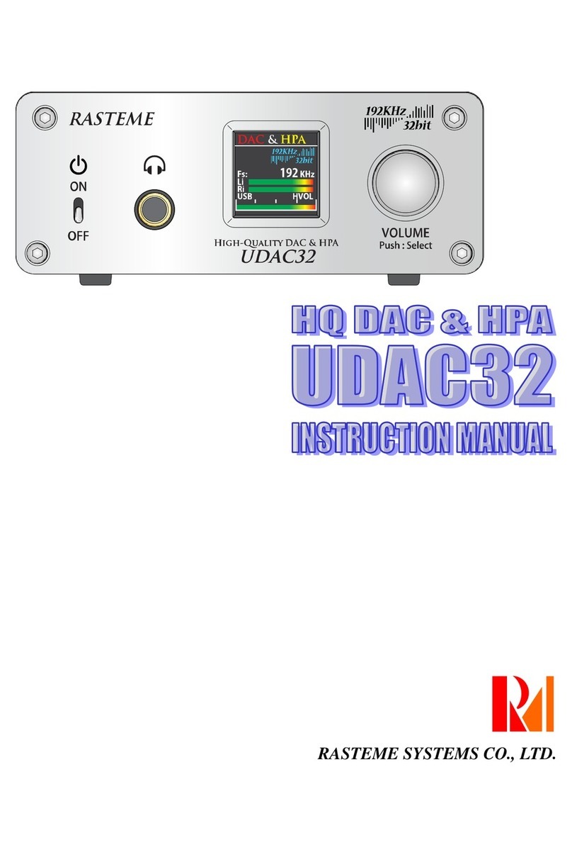
Rasteme Systems RAD192D User manual

RAD192D Instruction Manual
INSTRUCTION MANUAL
RASTEME SYSTEMS CO., LTD.

2
CONTENTS
RAD192D Instruction Manual .........................................................................................................................1
CONTENTS....................................................................................................................................................2
Safety Notices.................................................................................................................................................4
1. Accessories.................................................................................................................................................7
2. Features......................................................................................................................................................8
3. Part Names and Functions .........................................................................................................................9
Front panel..................................................................................................................................................9
Rear panel...................................................................................................................................................9
4. Installation of USB Audio Driver................................................................................................................10
4-0.System requirements.......................................................................................................................... 10
4-1. Installation.......................................................................................................................................... 10
4-1-1. USB audio driver installation.......................................................................................................10
4-1-2. DSD audio driver installation....................................................................................................... 11
4-2. MAC PC............................................................................................................................................. 11
5. Connection Method...................................................................................................................................12
5-0. Connection notice..............................................................................................................................12
5-1. Analog input signal connection........................................................................................................... 12
5-2. USB audio signal connection.............................................................................................................13
5-3. DSD OUT signal connection..............................................................................................................13
5-4. Digital audio output signal connection................................................................................................ 14
5-5. Power cable connection.....................................................................................................................14
6. Operation of Main Unit..............................................................................................................................15
6-1. Power input........................................................................................................................................15
6-2. Output volume adjustment................................................................................................................. 15
6-3. Output sampling rate change.............................................................................................................16
6-3-1. PC is not connected with USB .................................................................................................... 16
6-3-2. Windows PC is connected with USB...........................................................................................16
6-3-3. Mac PC is connected with USB...................................................................................................18
6-3-4. DSD is recording.........................................................................................................................20
6-4. Input source change...........................................................................................................................21
6-5. Meter change.....................................................................................................................................21
6-6. Input range adjustment ......................................................................................................................22
6-7. Display change ..................................................................................................................................22
7. Remote Control Operation Method...........................................................................................................23
7-1. Preparation ........................................................................................................................................23
7-2. Part names and functions ..................................................................................................................23
7-3. Output volume adjustment.................................................................................................................24
7-4. Mute................................................................................................................................................... 24
7-5. Output sampling rate change.............................................................................................................25
7-6. Input source change...........................................................................................................................25
7-7. Meter change.....................................................................................................................................25
7-8. Input range adjustment ......................................................................................................................26
7-9. Display change ..................................................................................................................................26
7-10. Battery replacement......................................................................................................................... 27
8. LCD Display.............................................................................................................................................. 28
8-1. Setting area........................................................................................................................................29
8-1-1. Connection status........................................................................................................................29
8-1-2. Output frequency.........................................................................................................................30
8-1-3. Input source ................................................................................................................................30
8-1-4. Level meter ................................................................................................................................. 30

3
8-1-5. Input range..................................................................................................................................31
8-1-6. Image setting...............................................................................................................................31
8-2. Level meter area................................................................................................................................32
9. SETTING switch ....................................................................................................................................... 33
10. Power Management Setting.................................................................................................................... 34
11. Monitor.................................................................................................................................................... 34
12. Abnormal Conditions............................................................................................................................... 34
Main Specifications....................................................................................................................................... 35
Contact us.....................................................................................................................................................38

4
Safety Notices
While using this machine, please follow the following guidelines to secure the safety.
The meanings of the marks are described as below.
Please read to understand them.
Warning It is possible that a user suffers death or serious injury because of
improper use.
Caution It is possible that a user suffers death or serious injury and property
damage because of improper use.
※The so-called property damage is including house, house belongings, livestock, and related
damage such as the pet, etc.
Meaning of marks
The left mark means general caution, warning and hazard.
The left mark means general prohibition.
The left figure means general compulsion (must do).

5
Please observe the following instructions in order to use safely.
Warning
Please do not disassemble or modify this machine because it
may cause electric shock and breakdown. Please observe
the instruction manual to repair or replace parts. Otherwise, no
action should be carried out.
Please do not use or store this machine in following places.
○extremely high temperature place (under direct sunlight,
near heater, on top of a machine which is hot and running.)
○Near water (bathroom, washing basins, wet floors etc.) and
humid places
○Dusty place
○Easy-to-vibrate place
○Poor-ventilated place
Please never put any external objects (flammable thing, coins,
metal needles etc.) and fluid (water, juice etc.) into this
machine.
Please make sure to insert the power plug into a safety
approved power socket within the designated power range.
Warning
Please do not bend the power cable with force, and do not put
heavy things on power cable. When the power cable is
defective, it may cause fire.
The volume setting may cause permanent unpleasant volume,
please do not use disagreeable high volume for long time
when you connect this machine with an amplifier and
headphone for use. In case of hearing loss or tinnitus, stop
using it at once and consult a physician.
In following situations, please turn off power at once and
disconnect power cable from power socket, and ask for repair.
○When the power cable or plug is damaged.
○When external objects or fluid goes into the machine.
○When the machine is wet.
○When the machine fails or malfunctions.
Please do not connect or disconnect power plug with wet hand
as it may cause electric shock.

6
Caution
Please locate the machine in a well-ventilated place during use.
Please hold the power plug for disconnecting or connecting the
power cable.
If the machine is not in use for a long time, please disconnect
power plug from the power socket.
When moving this machine, please make sure to disconnect all
the cables before moving it.
Please always install the machine in a flat location. Unsteady
and tilted places should be avoided.
Do not put volatile gases (pesticides etc.) on the machine or let
it touch gum, vinyl product for long time.
Please do not use thinner and benzene for cleaning the
machine. Use water-diluted neutral detergent and moisten with
cloths to wipe.
Caution USB does not support OS prior to Windows XP (Windows 98 /
Me / NT / 2000). They’ll cause system error and turn the screen
into blue and hang up.
Caution It is necessary to use our special USB audio driver for Windows
Vista/ 7 PC.
Please use the attached CD-ROM for driver installation.
Caution During the PCM USB recording on Windows PC, the OS other
than Windows vista and Windows 7 are not supported.

7
1. Accessories
Please make sure you have all the following accessories.
○Remote control: 1
○AC power cable: 1
○USB cable (USB (A type) ⇔USB (B type)): 1
(for USB AUDIO / DSD USB use)
○Instruction manual (on CD-ROM): 1
○DsdRecorder instruction manual: 1
○CD-ROM: 1
If the above accessories are not complete, please contact the purchase shop or contact us.
※Cables other than above mentioned are not attached. Please purchase separately.

8
2. Features
■192KHz/24bit PCM and DSD64 / DSD128 output compatible analog/digital converter (ADC).
■Support 5 digital audio outputs: PCM × 2 ( USB × 1 and OPTICAL × 1 ), COAXIAL × 2, AES/EBU × 1
compatible with max. 192KHz / 24bit.
■Compatible with USB Audio Class 2.0 (High-Speed, 192KHz/24bit) digital audio output.
■USB audio is Windows Vista / 7 (32/64bit special driver attached) compatible.
■DSD audio output is the output from USB(DSD OUT), making the direct recording on PC (Windows
XP~) available.
■DSD audio output is DSD2.8MHz(DSD64) and DSD5.6MHz(DSD128) compatible.
■OPTICAL output is S/PDIF 192KHz/24bit compatible x 1 Toslink connector.
■COAXIAL output is S/PDIF 192KHz/24bit compatible x 2 gold-plated Teflon®-isolated RCAconnectors.
■Built in highly accurate ±1.0ppm TCXO (Temperature Compensated Crystal Oscillator (-30ºC ~ +85
ºC)) that compresses the sound deterioration clock jitters and performs fast sampling, High bit rate
audio data processing and faithfully playback the sound source without distortion.
■Built in 2 analog inputs: RCA jack (unbalanced input) and XLR connector (3-pin balanced input)
compatible, available to switch from the machine or by remote control.
■Built in 3.5” TFT LCD display for displaying output sampling rate or sound wave.
■Built in electronic volume controller for controlling the output level. It’s available to adjust the output
level from the machine or by remote control.
Note: You can use our DAC (UDAC32, UDAC32R, UDAC192H) headphone or your existing DAC as
monitor during the recording.

9
3. Part Names and Functions
Front panel
1 POWER switch
POWER LED Power ON / OFF for this machine.
When the power is on, blue light will appear around the power switch.
2 IR receiver Receive signal from attached remote control.
3
Display area Display the current input source, output sampling rate, audio wave etc.
4 LEVEL / SELECT
Push: Menu Each time pushing this button, you can move the changeable items
and turn the button right or left to change the setting content.
When there is no item for selection, please change the output volume
setting.
Rear panel
5 RCA Analog audio (unbalanced) input connector.
6
XLR Analog audio (balanced) input connector.
7
USB AUDIO Output the USB audio signal to PC.
8
DSD OUT Output the DSD audio data to PC.
9
OPTICAL Output the digital signal (S/PDIF, TOSLINK).
10
COAX-1、2 Output the digital signal (S/PDIF, COAXIAL).
11
AES/EBU Output the digital signal (S/PDIF, AES/EBU).
12
SETTING For doing setting change.
13 AC100V
/ 220~240V Please use the attached power cable to plug to the power socket on
the wall.

10
4. Installation of USB Audio Driver
4-0.System requirements
CPU
Core i5 2.4GHz or above
Memory
4GB or above
VGA
1024×768, True Color (24bit) or above
Compatible OS
Windows Vista / 7 (32bit/64bit compatible)
※user account control needed.
Others
USB 2.0 available.
Internet connection available.
CD ROM driver available.
4-1. Installation
4-1-1. USB audio driver installation
It is necessary to install the special driver for Windows Vista / 7 (32bit / 64bit compatible) PC.
※Before installation, please connect the PC with the USB Audio OUT of this machine with the USB
cable.
Insert the attached CD-ROM into the PC, the Windows web browser will initiate and the menu screen
will be auto displayed. As soon as the menu is displayed, following screen will appear. Then, please
click [YES].

11
If the menu is not auto displayed, please click the「index.html」on the CD-ROM.
Then, click the 「RAD192D USB Audio Driver Installation (please do this for the first time)」from the
menu.
Besides, please use the browser of Microsoft Internet Explorer.
If security control screen as follows appears, please click the [Run(R)].
If installer has started, please click [Next>].
No matter how many times the screen appear, please click [Next>]to continue.
Soon, the driver installation will be completed.
4-1-2. DSD audio driver installation
Please refer to separate 「DsdRecorder」instruction manual for the DSD audio driver installation.
4-2. MAC PC
Under MAC, it works with the standard MAC OS driver 10.6.3 or later version. Do the [5-2. USB audio
signal connection], turn on the machine, the MAC OS will be auto detected and it’ll be available for use.

12
5. Connection Method
5-0. Connection notice
Incomplete connection will cause malfunction action or noise.
◎Please make sure the power switch must be always OFF when doing the connection.
◎Please do not connect the power cable until all the connections are completed.
◎Please make sure the plug is inserted firmly.
5-1. Analog input signal connection
It can connect the LINE (AUX) output terminal of record player ( phono equalizer ), master tape ( open
tape ), cassette disk, CD/DVD player, or mixer ( for live recording ) etc. via RCAor XLR cable.
※Except above listed connections, it’s possible to connect all other analog (Line / AUX) output
terminals.

13
5-2. USB audio signal connection
Connect the PC USB terminal with this machine’s [USB Audio OUT] connector.
The USB audio recording OS is compatible with Windows Vista, 7 and MAC OS 10.6.3 or later version OS.
※The high spec PC is recommended as it needs to do high speed data transmission during recording.
5-3. DSD OUT signal connection
Connect the PC USB terminal (USB2.0) with this machine’s [DSD OUT] connector.
The DSD recording OS is compatible with Windows XP, Vista, 7, 8.
※When both the USB Audio OUT and DSD OUT are connected, the DSD signal recording will have the
first priority. When the DSD recording begins, the USB Audio OUT will become invalid. Only when the
DSD recording is finished can the USBAudio OUT become valid.
※Please use the attached 「DsdRecorder」software for DSD signal recording.
※The high specification PC is recommended as it needs to do high speed data transmission during
recording.
※During the DSD recording, all speed from output connectors will become 176.4KHz.

14
5-4. Digital audio output signal connection
Connect this machine with the digital audio device’s (digital amplifier etc.) digital input terminal. Besides, it
can also connect a PC with digital input terminal.
(The signal output from RAD192D is stereo linear PCM. It is not compatible with AC3 or 5.1ch etc.)
When the COAXIAL cable becomes loose, please press the outer metal part (ground part) inwards and
make sure it will not loosen again.
Most cables are made to have slit for adjustment.
5-5. Power cable connection
Connect the attachedAC power cable to the machine’s power terminal on the rear panel and the power
socket on the wall.

15
6. Operation of Main Unit
6-1. Power input
1 Please double check whether the connection is
correct or not.
2 Press the POWER switch, the power will become
ON.
At this moment, the blue light will appear around
the POWER switch.
3 When the power is on, the machine will perform the
initialization, the [Opening Image] will be displayed,
then the Main image will appear and the machine
will become ready for operation.
6-2. Output volume adjustment
1 When no items can be selected, turn the LEVEL /
SELECT knob, the output volume will become
adjustable.
Turn the knob to the left (counterclockwise), the
volume will become smaller. Turn the knob to the
right (clockwise), the volume will become bigger.
2 When the volume value is changed, the volume
value (The value is displayed by figure and bar.) in
the setting area will change accordingly.

16
6-3. Output sampling rate change
6-3-1. PC is not connected with USB
1 Press the LEVEL / SELECT knob some times until
the 「Freq.」becomes orange color.
2 Turn the LEVEL / SELECT knob, the setting of
output sampling rate from each S/PDIF output will
become changeable. Please do the sampling rate
change based on following sequences.
⇔
44.1KHz
⇔
88.2KHz
⇔
176.4KHz
⇔
48KHz
⇔
96KHz
⇔
192KHz
⇔
6-3-2. Windows PC is connected with USB
When the Windows PC is connected with USB, it is not possible to do the sampling rate change from
RAD192D main unit
Please do the setup of sampling rate under PC sound properties.
Regarding sound properties,
please click the 「Hardware and Sound」in the control panel.

17
Then, click 「Sound」.
Push the recording tab, the recording device will appear. Please select 「RAD192D」.
Do the sampling rate setting under the [Advanced].
※For Windows PC, only 44.1KHz, 48KHz, 96KHz, 192KHz are available for selection.
(Windows does not support the 88.2KHz and 176.4KHz.)
※Output sampling rate from each digital audio output connectors are the same as the USBAudio.
※You can do the USB Audio recording by using the Windows attached [Sound recorder] or other sound
editing software. Please refer to their respective user manual or help for the software setup.

18
6-3-3. Mac PC is connected with USB
When MAC PC is connected with the machine’s USB, it is not possible to do the sampling rate change
from RAD192D main unit.
Please select “RAD192D” under sound setting. Then, do the sampling rate setting under Audio MIDI
setting.
Open [Apple mark] →[System Preferences…], or double click [System Preferences] in the
[Applications].
When the [System Preferences] is open, please click [Sound] under the hardware.

19
Select [Input] under [Sound]. Then, select [Line 1 (type:USB)].
If the [Line 1 (type:USB)] does not appear here, it is possible the power of this machine is not on or the
USB cable has not been connected. Please double check the cable connections etc.
When multiple USB input devices are connected, the number in [Line 1] may become different.
Under this situation, please select RAD192D as the input device.

20
Then, do the input sampling rate setting.
Open the [Audio MIDI setup] according to the
sequence shown in the left picture.
Finder → Applications → Utilities
→ Audio MIDI Setup
The [Audio Devices] window is open.
Select the [Line 1] from the left device list.
Then, it is possible to select the input sampling frequency from the right [Format].
※The sampling rate from each digital audio output connectors will be output based on above setup.
※You can do the USB Audio recording by using the MAC OS attached [GarageBand] or other sound
editing software. Please refer to their respective user manual or help for the software setup.
6-3-4. DSD is recording
It is not possible to change the sampling rate during the DSD recording. All signals output from S/PDIF
will become 176.4KHz. Furthermore, the USB Audio OUT will become invalid during the DSD recording.
※Please do the DSD recording with the attached 「DsdRecorder」software.
※Please refer to separate 「DsdRecorder」instruction manual for the software operation.
Table of contents
Other Rasteme Systems Media Converter manuals