WITTUR iAStar AS380 User manual

Manual
iAStar AS380
frequency converter with integrated lift control
system
Version E2.0 (MAI)

Content
Table of Contents
1. iAStar AS380..................................................................................................1
Characteristic...................................................................................................1
scope of operation...........................................................................................1
2.Overview of system.........................................................................................3
Integrated frequency converter iAStar AS380................................................3
Car controller panel SM02..............................................................................3
Command board panel SM03..........................................................................3
Display & control board SM04.......................................................................3
Special board SM09........................................................................................4
Functional overview........................................................................................4
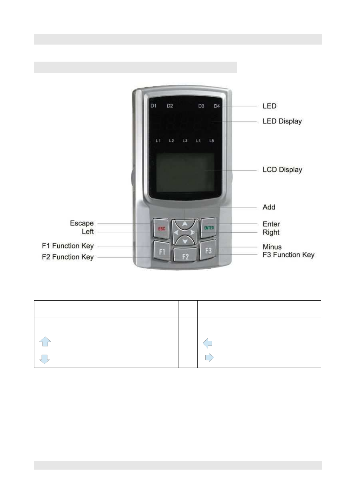
3. Hand device....................................................................................................7
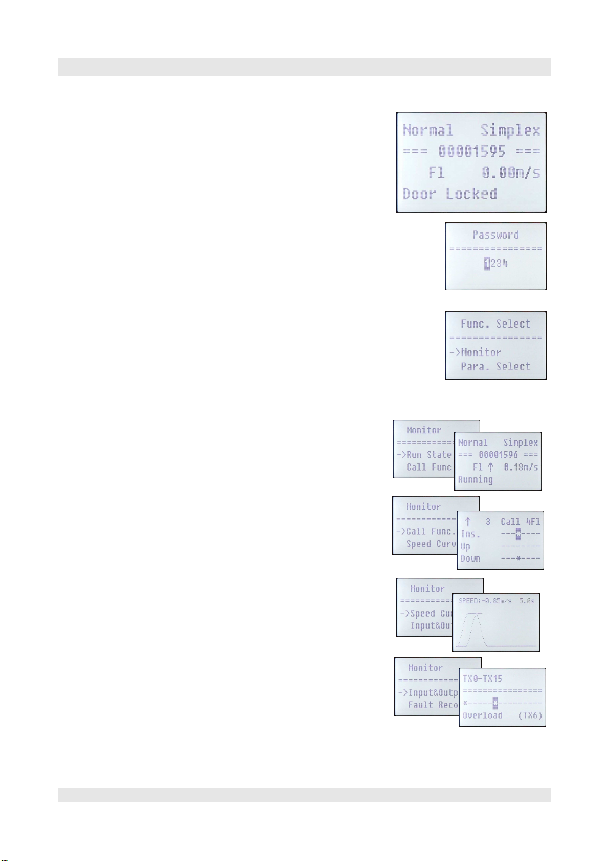
operation:.........................................................................................................8
Log in:..............................................................................................................8
Menu................................................................................................................8
State menu under „Monitor“..........................................................................8
To set parameter in the submenu Para.Select..................................................9
different functions (Func.Select)...................................................................11
4. Menu tree & parameter..............................................................................13
Basic Parameter.............................................................................................15
Comfort Adjust:S-Curve...............................................................................15
Comfort Adjust: PI Adjust............................................................................16
5. Commissioning -Installation run................................................................17
Condition for commissioning run:................................................................17
Groupfunction................................................................................................18
Security loop – Return-motion -control........................................................18
First movement with the Return-motion -control..........................................18
Setting the parameters on AS.T030...............................................................18
Checking parameters for commissioning and eventually adapt....................20
Parameter speed controller............................................................................22
HDR Lock Error............................................................................................23
6.shaftcopying..................................................................................................25
Re-levelling -sensor.......................................................................................26
Magnetic switch............................................................................................26
Correction switches.......................................................................................26
Inspection endswitches..................................................................................26
Intelligent Magnetic sensors iMS45...........................................................27
Design and function.......................................................................................27
Correct signal Inputs at AS.T030 (LEDs)....................................................28
7.AS380 Main board AS.T029........................................................................31
AS.T029 connections:...................................................................................31
8.SM02/H cartop box module.......................................................................35
9.SM09IO/B Add-ON module.......................................................................37
10.SM02/G car panel board-module.............................................................39
SM03 button-module.....................................................................................40
11.SM04HRF floor module.............................................................................41
12.Security Section..........................................................................................43

Content
Security circuit..............................................................................................43
Optional security switch................................................................................43
Security circuit..............................................................................................44
Components...................................................................................................44
Additional Monitoring by control.................................................................45
Scan control at the security circuit................................................................45
N-wire............................................................................................................46
check..............................................................................................................46
Pilot relay.......................................................................................................46
Monitoring of run..........................................................................................46
CHECK..........................................................................................................46
13.Advice of acceptance test...........................................................................47
Generally.......................................................................................................47
Isolation measurement:..................................................................................47
Check of run-time monitoring:......................................................................48
End switch movement:..................................................................................48
Effectiveness of the brakes ( one-sided brake)..............................................48
Contactor monitoring:...................................................................................48
Brake monitoring switch:..............................................................................48
Measurements in security circuit...................................................................49
Triangle monitoring „DKU“.........................................................................49
Instruction for A3 check................................................................................51
14.Parameterlist...............................................................................................55
15.Error code...................................................................................................69
16.Displaycodes................................................................................................73

Manual-overview of system
1. iAStar AS380
Characteristic
•
Converter and control in one unit
•
Reduced wiring
•
simplified parametrisation and commissioning
•
32bit processor ARM7 industry standard
•
Dual processor design for enhanced safety requirement
•
2x CAN interfaces for internal & external communication
•
High EMc-stability (EFT-4000V)
•
High ESD-stability (ESD 8000V)
•
EN81, GB7588, CE certified
scope of operation
•
For synchronous and asynchronous drive
•
numerous parameterizable operations for almost all types of lifts.
•
Lifts from 0,1m/s to 10m/s.
•
Up to 64 stops
•
2 group cluster integrated
•
up to 8 in one group with group controller
•
prepared for call control
•
shaft copying by shaft encoder and magnetic sensor
•
compensation of load during start with and without load
measuring unit
•
ID-card system( id card-transponder) integrable
•
remote monitoring local and global
•
7 segment disply on board
•
graphic LCD on separated handtool
•
depiction of driving cycle, input & output state,statusinformation
•
error memory (20 errors) with real time registration plain text display.
•
Standard for two cabindoors
•
numerous special functions eg automatic evacuation .with load dependant selection of direction
Seite 1

Manual-overview of system
2.Overview of system
SmartCom is a modern, on newest technology based control system
especially for elevators.
The system consists basicly on compnents as follows:
•Control circuit terminal iAStar AS380 with integrated frequency
converter
•car controller panel SM02G
•command board SM03 panel for keys
•Car top control board SM02H
•Display& control board SM04
•Extension board SM09
Different variations from each of the the panels/ boards enables an
otimal match between the control system and the elevator in the
required range.
Simple or complex controls based on the always consistent CAN-
records could be implemented.
All components are combinable and extensible due to the CAN-
system .
Integrated frequency converter iAStar AS380
This modul optionally in the shaft or outside consists of the frequency converter and the central unit
SM01 of the elevator control. It includes all functions, especially the drive control, detection of car-
position and a lot of special functions, which are normally allocated in the shaft or engine room.
It communicates via the CAN-Bus with the other modules.
Car controller panel SM02
All functions which are related to the cabin are realised by the car controller panel . It is connected
via CAN-bus with the control circuit terminal.
There are two variations. The „classic“ which only one SM02/03, and now with the 32bit board
F5021 established fragmented variation. In this case there is integrated one SM02/H in car top
control panel and one SM02/G the car controller panel. Thus the 36-pole cable is reduced to a 12-
pole control casble between the car top panel and the car controller panel. The connection from up
to three additional car controller panels/ console panel is now very easy via CAN-bus.
Command board panel SM03
This board is connected to the car controller panel. Up to 8 panels can be connected to an SM02.
One command board provides 8 inputs & 8 outputs for the related confirmations.
Display & control board SM04
Those boards could somehow used as floor-display in the cabin or other as floor display for each
floor with indication of floornumber and continuing indicator.
Seite 3

Manual – overview of system
The adressing is made by DIL-switch or the floor button.
The SM04 is available in different designs: Horizontally, vertically and vertically-slim. The
diplays varies in design and circumference and can also be customized.
All SM04 can communiucate via CAN-bus and are combinable in any order.
In the floors on the SM04 Modulen (Disply+CAN-Modul) the push-buttons for the hallway calls
and the key-switch for special function. Newer panels permit also to connect a loudspeaker for the
EN81-70 required beep.
Special board SM09
Via those customized special functions could be realised without changing the control circuit. For
example the electronic electronic custodian system of the customer or additional fault-messages.
Functional overview
Standardfunctions
1 Group controllers Collecting hall calls with respect to the given direction
2 Inspection run Up or down. In the door zones the door open button can be used to open
the door.
3 Self liberation with slow drive If you miss the door zone in normal mode the elevator drives slowly with
closed door into the levelling position and opens the door.
4 Testrun For Testpurposes the elevator can make a determined number of random
testruns
5 Realtimeclock Errors are registrated with date and time. Functions can be temporary
activated
6 Time to keep doors open Dependant of the kind of call ( Interior, exterior, service, special call),
the time to keep the doors open can be indicated.
7 Door opening by local calls Is the elevator allready in the floor from which the call comes, the door
opens.
8 Premature closing of the door. With the door close button the door can be closed before the „Door
open-Time“.
9 Forced opening of doors Inside the the door area with the door open button the door opening can
be forced for closed doors which are actually closed.
10 Return motion automatic In case the cabin is not closed within 15 sec. after arrival at the door-
close endswitch, the door open again for a new try.
11 Monitoring of door opening If 15 sec. After opening of the door the final door switch is not the door
closes for a new try.
12 Cancelling of call Via double -CLICK of a call button the call can be cancelled.
13 Terminal landings In the upper terminal the UP command is deleted; in the lower terminal
the down command is deleted.
14 Direct drive Direct drive without rat run. Is activated when incremental copying and
analogue control. The travel curve at this will be created by the
controller,
15 Cabin Full If full load, the cabinet do not stop anymore for hall calls
16 Cabin door light OFF After 5 Minutes without activity the cabin light is switched OFF
17 Parking drive After a ajustable time without activity the elevator drives into main floor
18 LCD control Graphic display with extensive status information and menu navigation
19 Analogue speed setting. The rotation frequency of frequency converter is guided by the analogue
output.
20 Digital speed inputs Optional the speed can be set via contacts.
Seite 4

Manual-overview of system
21 Error storage 'the last 20 errors are stored with time, floor no and error code
22 Learning movement for shaft infos The control learns via encoder and the floor flags the shaft measurements
and braking distances. After this the elevator can drive in normal mode.
23 Clearance of floors Setting of floors which can be reached.
24 Setting of floor indicator. The signs which appears in each floors can be selected
Liftboy control The elevator is driven manually via car controller panel. Hall calls are
served.
26 Priority inside Hall calls are deactivated. Only inside commands are effective.The door
had to be closed by door close button. The button has to be pushed until
door close final switch is reached.
27 LED-dot matrix display,
LCD graphic display In each floor is a dot matrix display which indicates floor stand, direction
and status. The user can see wether something is going on.
28 Display with roll funbction According to the drive direction the display is rolling.
29 Automatic correction of shaft datas. The shaft informations are continously corrected..
30 Remote deenergisation The elevator can be disengaged at which all ongoing car/ cabin
commands are executed prior to shut off..
31 Door is only opening in door zones. Out of the door zones the the cabin door cannot be opened.
32 Light barrier/ light curtain Light barrier/ light curtain is evaluated by control and prevent door
closing if activated
33 Overload When overloaded the door remains open and buzzer is going on.
34 Misuse detection If cabin is empty the cabin calls are limited.
35 Direction of rotation Is a wrong direction of rotation is detected elevator stops.
Route monitoring Is the cabin not moving despite active drive the drive stops after 40 sec.
New runs only after reset possible.
37 Monitoring traction Is cabin moving despite stop od drive alarm is engaged.
Limit switch inspection run Limit switches prevent that elevator is running into emergency limit
switches during learning movement or bring-back run.
39 Contractor monitoring This control checks during every run the function of main and brake
contactors.
40 Speed monitoring When overspeed >emergency stop!
41 CPU Monitoring The processor is monitored via watchdog and restarted if necessary.
Optional functions
1 Preopening doors Via safety circuit
2 Fine levelling with open door Via safety circuit. For hydraulic standard function
3 Fire control system When fire signal run elevator in fireman floor and stays with open door.
Fireman control All commands are dropped and the elevator runs into fireman floor. Now
the firemen can use elevator.The doors doesn't open automatically but
has to be opened with door open button. Release of button actuates
immediate closing-european (EN81) und russian (PUBEL) option
5 2
nd
car controller panel A second car controller panel can be easily fixed.
6 Car controllerpanel for 2. door selective door control
7 Handicap panel Own panel (eg desk panel) for handicaped people longer door open time
8 Duplex-Function Via 2
nd
CAN-Bus two elevator can be connected to a 2group-system.
The elevators share the calls correspondant the actual situation in order
to reduce the waiting time to a minimum.
Addionally a function could be activated which brings the nearest
elevator to the parking level to dispose him (waiting).
9 Groupfunction In an optimal control up to 8 elevators can be combined to a group.
The group control collect the hall calls and dispatches correponding the
actual location of the elevators to reduce finally the waiting time to a
minimum.
10 Rush hour filling building Via internal time settings the haul capacity can be adapted ( typically
Seite 5

Manual – overview of system
office building)
11 Rush hour emptying building Via internal time settings the haul capacity can be adapted ( typically
office building)
12 Dispatch waiting elevator When all calls are executed after 1 min the elevators of a group are
distributed in the building; one is going to the main parking floor the
others remaining in different parking positions to reduce waiting time.
13 Interface to building control system RS485 interface to link to PC for building control
14 Remote monitoring The elevator can be integrated in an overall remote monitoring system.
15 Drive in Gong During the landing approach a gong under the floor or over the ceiling of
the cabin informs about the arriving cabin.
16 Driving on displays HOP In the hall indicator panels with an accoustic and optical display could
be integrated.
Floor gong In every floor a Gong could be provided.
18 Card reader in the cabin With a transponder card could either a specific call be released or
presetted calls be released
19 Card reader in the floors Release of hall calls
20 Selective door control Back-and frontdoor could be separated.
21 Push mode After 1 min the door is closing slowly despite the light array.
22 VIP Service A key switch in the HOP deletes all hall calls and brings the empty
cabine. Now several inside calls could be setted. After this the elevator
switches back in normal mode.
23 PIN entry via call button For specific selection of floors the call buttons can be used to entry a
PIN
24 Floor activation locally controlled For simple or duplex elevators an altered setting of floors can be entered
via key switch.
25 Floor activation via group control Floor settings can be temporarily changed via groupannexe
Temporarily blockade from
individual floors Floors could be blocked for short time from the user.
27 Automatic Evacuation In case of a power failure with following emergency power supply the
cabin runs to the next floor
8 Emergency power evacuation For elevator groups the evacuation is made one after another.
9 Earth quake Function Elevator stops during run and brought to the evacuation stop.
30 announcement Serial and parallel connection for announcements
Seite 6

Manual-overview of system
3. Hand device
ESC Parameter/leave menu ENTER Select parameter,
set parameter/take over param.
F1 & F2 Quick select from error storage, In-Out
display- , CAN- and shaft encoder F3 Quick select graphic drive curb
Next Parameter/menupoint
Increase of choosen decimalplace Jump back 10 parameters/
one decimal point left
previous Parameter/Menupoint
Decrease of choosen decimal point Jump forward 10 parameter
one decimal point right.
Seite 7

Manual – overview of system
operation:
In normal case the state, the group affiliation, actual floor, actual
speed and the actual state of doors or drive
The number in the 2
nd
line depicts the counter of runs can also be
setted for another value.
Log in:
To see the state or to set parameter you have first to login. After
pushing the ENTER button appears the password. Standard for the
Password „1234“. After login under Chg.Password“ the password could be
changed.. Attention! Don't forget Password! The control can be unlocked only in
the fatcory without Password!
Menu
The complete menu tree you'll find under „ Menu tree & parameter.
The Startwindow shows state, group affiliation, actual floor, actual speed and the
actual state of doors or drive.
With „ Enter“ you're going to main menu. Again Enter select Monitor-Menu,
which has all diagnosis windows.
State menu under „Monitor“
Run State conforming to the start
In the first line you see mode (Normal, Inspection, Fire Return, Firemen, Park)
and state of group (Simplex, Group).
Below counter of runs, Floor, speed and the actual action.
In Call. Func. The actual calls are depicted and you can also set calls (with the
arrow up/ dwn and Enter).
Cabin calls, hall calls up and down.
Speed Curve is the graphic depiction from speed encoder.
Above the actual speed and running time is indicated.
In the window Input&Output all inputs and outputs are depicted.
With the up/dwn buttons youre switching between the 16er groups.
With right/left a single input/ outout could be marked. In the line below
appears the function of this input/ output.
The designation X (Input SM01) and Y (Output SM01), plus TX (Input
SM02) and TY (Output SM02) you'll find in the electrical circuit.
Seite 8
Startwindow
Login
Main menu

Manual-overview of system
In the fault Record the last 20 faults are depicted with date, time and which
floor.
The newest fault ist always shown at first.
With UP/ down you're moving between the entries in the list. With ENTER a
new window appears with date, time and clear text entries.
The list Shaft Data includes the floor positions which had been determined
during the learning movement in mm. By this you can easily check wether the
positions had been correctly detected during the learning movement.
The windows Encoder Eva und Communication are helpful when problems
with the encoder or CAN-bus occurs.
In the version window date and version number of the firmware are shown.
Before updating you should check wether the update is more actual then the
existing one.
To set parameter in the submenu Para.Select
Via the parameter menu you can acceed on numerous parameters.
There are groups of parameters where the parameters are thematically
arranged. For example motor or door parameters. There is also a list where
parameters are asorted though numbers.
Most of parameters could only be set in inspection -or return motion mode. If
the warning appears switch to inspection mode.
All parameter are set in 16bit integer numbers. Most of them in decimal
numbers together with the unit.
Eg 50 with a setting of 0,1 s means 5 seconds.
Some of the parameters only exist as a bitmask. Depicted is a decimal value,
but as soon you want to set a value the bitmask appears and with left/ right you
can move and set or delete the values.
(* means set, - deleted).
In the lower line appears the description of the Bits.
By this for every input the logic break/ make contact could be individually set.
Seite 9

Manual – overview of system
Insp.Option include all parameters which are necessary for the start-up in the
inspection mode
S Curve is needed for the use of the analogue Output of the converter control.
Lvl.Mic.Adj. Enables the correction of each levelling at every floor.
Normally not necessary because the floors are calibrated during the learning
movement.
Multi Speed includes all parameter, which are necessary for the run of the
converter in multistep-mode ( parallel control).
Door Control enables the parametrisation for door control.
Flr.Disp. Leads to the list of the floor idicators.
For every floor you can set individually the displayed letter combination (for
Step SM04 displays). The announcement for the landings on each floor is
fixed by this dsiplay code.
The Display codes are stated in a chart in the appendix.
Service Floor determines the enabled floors. Also the floors which are only
enabled by key-switch are determinded.
Block Floor permits blocking of a floor via time or key switch..
Comp. Stop (enforced stop) defines stops where the elevator is brought to an
enforced stop when passing by. Make sense in some cases for Hotels.
Heavy Traf. Permits the function „emptying/ filling building“.
So the haul capacity of a office building could be increased
In Test Run the parameter F34 can be set for a number of runs, which the
elevator should make without any command for testing purpose.
Para. Setup is the access to the complete parameterlist.
Reset brings all parameters to factory setting. Has only be made if absolutely
neccessary! Before the Reset a number has to be entered to avoid an accidantly
reset.
Attention! After the entry of the number the reset is made without any further
inquiry!
Set F146 imperativly on 0 !
Seite 10

Manual-overview of system
different functions (Func.Select)
Time Setup: setting of then realtime-clock. Is needed for the fault-record and
the time dependant enabled floors. And also for the function „filling/ emptying
building“.
Door Teach: detect via opening and cloasing the function of the door-
endswitches.
Shaft Teach: has to made imperativly before going to normal mode ( after
mounting or changing door position)
Door, bus, shaft copying and cabinlight has to work correctly.
After activating of shaft teaching the elevator runs in the lowest stop and starts
with the learning movement.
After finish the elevator can go into normal mode. If an error occurs the
learning movement is stopped and an error messages appears..
Reset Para.F: Rest on factory setting!!!
Reset Errco.: deleting of fault record!
Error Reset: Reset after Lift Error (fatal fault) eg. Run monitor, contactor
monitoring, Bakemonitoring etc..
Relogin: Logout and relogin.
Normaly after 10 min. without input automatically logout!
Chg.Password: changing Password
Attention! Don't forget password-could only be resetted in factory!
Seite 11

Manual-overview of system
4. Menu tree & parameter
Function main sub description
Monitor Drive Status Elevator status (Floor, speed etc.)
Call function. Calls for side A and depict
Speed curve Graphic depiction of drive curve
Input&Output X0-X15 Status from In-outputs
X16-X31 Status from In-outputs
GX0-GX15 Status of inputs on SM02 in car controller panel
HX0-HX15 Status of inputs on SM02 car top panel
Y0-Y15
Y16-Y31
error record Error record
Shaft Data floor Pos. List of the floor datas
switch Pos. Positions pre-limit switch
Self-diagnosis CAN Com. Eval.. Diagnosis of CAN interfaces
Encod. Eval.. Analysis of encoder
Call diagnosis
Version Depiction Software-Version
Para.Type Basic-Param.. Basic-Parameter
Comfort Adjust. S-curve s-curve-parameter
PI Adjust. Inpection-parameter
Lift Model
Motor Model
Level Adj.
Level micro adj Level Micro Adjustement
Input Type Input-polarities(NO/NC)
Flr. Disp.. Set code for Floor display
Door control Door parameter
Dr Open Allow Enable doors
Service Flr. Enables floors
IC Setup
Time blck Flr.
Parameter F All parameters in one list
Reset Lift P.
Rest FU Pa.
copy Para Dnload OP Parameterdownload into . Handdevice
(*1)
Upload to MB Parameterupload back into control circuit terminal SM01
(*1)
Seite 13

Manual – overview of system
Comissioning Shaft tech Learning movement
Motor teach
Test Menu Up limit test Measuring end switch up
Dn. limit test Measuring end switch down
Drive test Test run monitoring
M.cont. test
B.cont.Test
Brake swi.Test
A3Test UP
A3Test Down
Terminal Call.
Testrun Number of random testruns
Load adjust. Load teach
Load Status
Door operate
Reset Reset Errcode Reset error record
Reset LiftP. Reset Steeringparameter on factory setting.
Reset Inv.FU Pa. Reset Inverter parameter on factory setting.
Reset times
I/O Reset Reset of Input/ Output functions
Additional
funct. Time Setup. Set time
Input sel
Output sel
floor Offs.
Home flr setup
Fire mode.
Gc mode
Homing delay
Gong Output
Fan& Light time.
Attd Mode
Call type
Call Cancel
SM01 limit
MB Num. lmt.
Seite 14

Manual-overview of system
Sel English Sel Deutsch
Relogin
Chg. Pwd.
Relogin 'Relogin
PWD aende. Change Password
Basic Parameter
Nr. Standard Beschreibung Hinweise
F6 1m/s Rated elev. speed
F204 12.0A Rated current motor
F211 2048ppr Encoder resolution
F11 18 Number of floors
F36 0 Brake switch. M.
F153 0 Deadbolt monitoring
F156 0 Check of security loop
F25 35296 Setting for each I/O, if (NO=normally open)
(NC=normally closed)
Depends on the circuit and the connected switch
Bitmask
F26 83
F27 835
F28 0
F202 1
Type of motor
1= Synchron-Motor
F203 4,7kW
Ratet motor power
F205 29,4 Hz
Rated motor frquency
F206 160RPM
Rated motor revolution
F207 360V
Rated motor tension
F208 22
Number of poles
F235 32,00%
No-Load current factor
F210 2
Type of encoder
2 = EnDat
Comfort Adjust:S-Curve
Nr. Wert Beschreibung Hinweis
F0 0,55m/s² acceleration
F1 0,55m/s² retardation
F2 1,3s Curve adj Start
F3 1,1s Curve during transition const. run
F4 1,1s Curve during left constant run
Seite 15

Manual – overview of system
Nr. Wert Beschreibung Hinweis
F5 1,3s Curve during stop
F13 0,03m/s Bring-back- in position-speed VN
F16 0,6s Brake retardation
F17 Retardation Inverter unlock/ enable
F181 0,5s KMY Delay (fix)
F175 0,006m/s Creep speed
F186 0,7s Time for creep speed during Start
F193 50,00%
F194 50,00%
F195 50,00%
Comfort Adjust: PI Adjust
Nr. Wert Beschreibung Hinweis
F212 40 ASR P0 PID Parameter during start-
up/ Stop(Zero Servo)
F213 60 ASR I0
F214 0.5 ASR D0
F215 40 ASR P1 PID Parameter for the range
>0 but <F0
F216 60 ASR I1
F217 0.5 ASR D1
F218 40 ASR P2 PID for the range >F0 but <
F1
F219 60 ASR I2
F220 0.5 ASR D2
F221 40 ASR P3
PID for the range >F1F222 60 ASR I3
F223 0.5 ASR D3
F224 1,00% Change Frequency F0 limit F0
F225 50,00% Change Frequency F1 Limit F1
F226 0,8s V0-Holding time
Seite 16

Manual-overview of system
5. Commissioning -Installation run
Attention! Before start for the first time, check wether CAN-Bus is inactive ! Means that JP4 on the circuit
AS380 terminal is disconnected!
By this blocking from HDR Lock Error (Steuerung had detected bypassed security loop)is avoided. Is
blocking already active see HDR Lock Error.
General:
Installation and commissioning should only be made from personel which is familiar with the electrical and
mechanical mannerism of the elevator. Deficient commissioning or installation can provoque risk for life and
limb.Due to the characteristcs bypasses have to be made during installation. Most of the bypasses are already
set for testing reasons on the test facility.
During the installation process those bypasses are removed and replaced by security switches.
As soon as a new component is mounted eg folding support, loop into the security circuit!
On sheet 3 of the wiring diagram the complete security plan is depicted.
Check all security switches on their correct function and effectiveness.
Especially the switches on the fold -away-bracket in the security space and the folding support.
At X88 on Servicepanel measurement in the security loop could be executed.
Condition for commissioning run:
•
Drive, Control cabinet, service panel and brake resistance are mounted and connected. (don't
forget Temperature monitoring at X4.3 and X4.4 eventually bypass otherwise K0 doesn't actuate.
•
Car top control is fixed and connected via the trailing cable. If not so, provide bypasses (sheet 3)
and switch S50 on Inspektion.
•
Sheelds from motor, brake resistance and encoder are correctly placed.
•
Security loop is closed up to X20 (display on inverter LED board or on Service Tool in
Monitor/Input-Output X20 und X21).
•
Check parameter on Servicetool (see Details below)
•
Now push Inspecion Auf or Ab , the Motorcontactors should actuate and the inverter should
execute for 1
st
time a tuning (Phasenwinkel) . Identifiable by a noise. (If Contactors don't actuate,
check wether security loop is closed while switch „Inspektion / Auf/ Ab“ is pushed up to X21
-otherwise a bypass is missed or a switch is open-indication on service tool.
•
Motor should slowly start after the „tuningnoise“. If he is jumping, repeat tuning (for this set
Parameter F242 at 0 and restart commissioning)
•
If motor is still jumping, change two phases and repeat previous pace.
Seite 17

Manual – overview of system
Groupfunction
The parameters for the groupfunction has to be set as follows::
–
F23 = 3 (on each control, which is in a group)
–
F181 = 0-7 (Number of elevator in one group-the lowest number has highest priority
)
Security loop – Return-motion -control
First ashure that security loop is closed
If it is necessary to bypass parts of securityloop, precautionary measures has to be taken for
running the cabin.
One has to make shure that nobody is in the range of the doors or in the shaft!
At first connect all existant security switches and elements
If this is not possible the relevant strapping plugs should be placed.
First movement with the Return-motion -control
When it is checked that there is no danger of collision first run with return-motion-control could be
made.
If the elevator does not move in the intended direction, the correct rotation direction should only be
set via the inverter.
Please go to following menu part
F - XXX
Parameter F234 = 0 (change to 1)
Parameter F234 = 1 (change to 0)
Setting the parameters on AS.T030
Depiction 7-Segment Display on a AS.T030 board in normal operatin state
Seite 18

Manual-overview of system
When pushing the arrow push-button left and right the menu points are depicted
choose menu „LOGIN“.
Now the 4-digit password could be entered. By pushing the up/down arrow you set the number, by
pushing left/right the ciphers are set. The cipher is blinking in a 1 sec pulse. Password: 1234
The authorization for changing password is now enabled
.
When pushing left or right the parameter menu could be choosed.
Seite 19
Push Enter
Push Enter
Table of contents