rauland CRT3 User manual

RAULAND-BORG CORPORATION
l
3450 West Oakton Street, Skokie, Illinois 60076-2951
l
(708) 679-0900
PRELIMINARY
DESCRIPTION MOUNTING PARTS
The CRT3 is a dial-less telephone designed for use with
the Rauland Telecenter@ systems. On the Telecenter IV
and Telecenter TCS, it can serve asa single-link or a multi-
link staff phone. On the Telecenter 5500, it can serve as a
common-line staff phone in conjunctionwith an ADS55 10
Console and an RS503 Staff-Telephone Adapter.
In addition to the standard“tip”and“ring”wiring, the
CRT3 has a second pair of contacts that provide a dry con-
tact when the phone is lifted off-hook. This connection
enables the phone to call in when the handset is lifted.
Important: Never connect the CRT3 to the modular
jack of an Administrative Display Telephone: the CRT3’s
extra set of contacts would place ashort across the display
lines.
The telephone comes with the following mounting
parts:
Qty.
Description
1
Modular jack.
1 Short four-wire connector with amodular plug ateach
end.
1 Long four-wire connector with a modular plug at each
end.
2 #632 x ~3%” machine screws.
1 Locking clip (to secure the phone to the mounting
plate).
The CRT3 has been approved by the Federal Commu-
nications Commission (F2SGBN-7273S-TE-E) .
This Telephone is Not Hearing-Aid Compatible.
The following will need to be supplied by the user:
4 Wiring ftom the Telecenter to the telephone.
4 Single-gang electrical box.
4 On the TC5500: ADS55 10 Console, RS503 Module,
and speaker.
INSTALLATION
These instructions tell how to mount the telephone.
Wiring diagrams are included in the main Telecenter IV
manual (K&1435), the Telecenter TCS drawings manual
(KI-1550), and in the installation manual for the ADS5510
console (RI-1557). The installer is responsible for comply-
ing with all local codes and the National Electrical Code
or the Canadian Electrical Code.
shields to ground (see KI-1551). For the Telecenter IV,
Step 1. For the TC5500, use shielded conductors;
conduit is also strongly recommended. Connect all
Step 4. Fasten the system wires to the appropriate
screw terminals. Push the front plate onto the module.
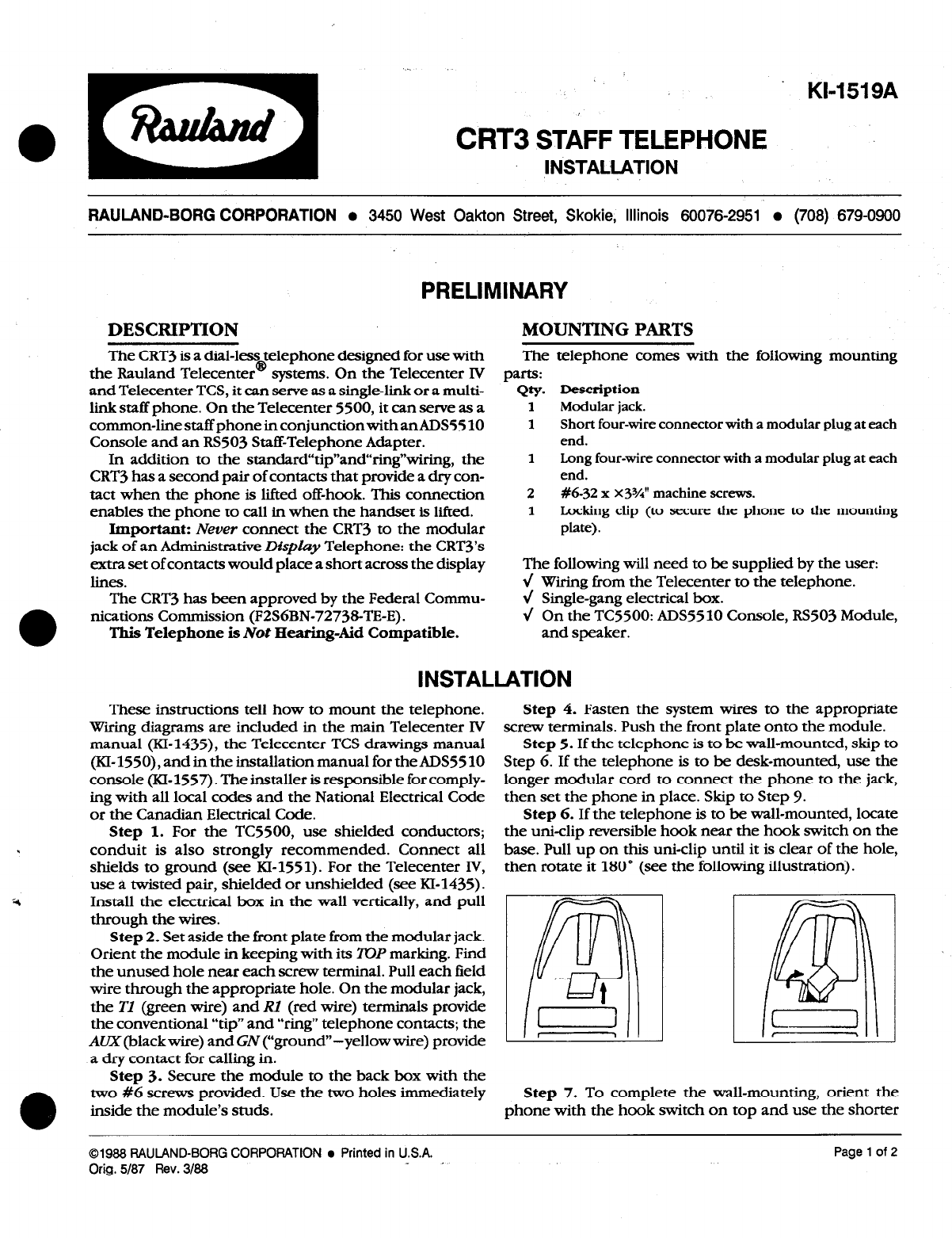
then rotate it 180” (see the following illustration).
Step 5. If the telephone is to be wall-mounted, skip to
Step 6. If the telephone is to be desk-mounted, use the
longer modular cord to connect the phone to the jack,
then set the phone in place. Skip to Step 9.
Step 6. If the telephone is to be wall-mounted, locate
the u&clip reversible hook near the hook switch on the
base. Pull up on this uni-clip until it is clear of the hole,
use a twisted pair, shielded or unshielded (see RI-1435) 1
Install the electrical box in the wall vertically, and pull
through the wires.
/;
m ’
I! u 1
-
1
Step 2. Set aside the hont plate from the modular jack.
Orient the module in keeping with its 7OP marking. Find
the unused hole near each screw terminal. Pull each field
wire through the appropriate hole. On the modular jack,
the TI (green wire) and RI (red wire) terminals provide
the conventional “tip” and “ring” telephone contacts; the
AUX (black wire) and GZV(“ground” -yellow wire) provide
a dry contact for calling in.
Step 3. Secure the module to the back box with the
0
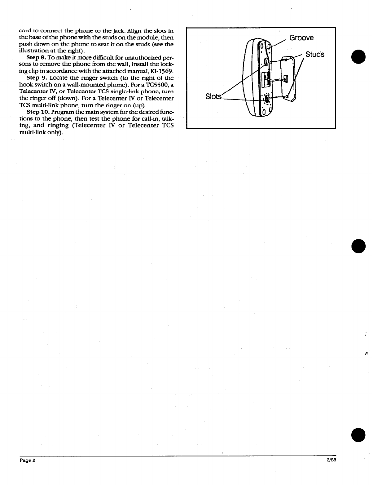
two #6 screws provided. Use the two holes immediately Step 7. To complete the wall-mounting, orient the
inside the module’s studs. phone with the hook switch on top and use the shorter
01988 RAULAND-BORG CORPORATION
l
Printed in U.S.A.
Orig.
5187 Rev.3188 _ .
Page 1 of 2

cord to connect the phone to the jack. Align the slots in
the base of the phone with the studs on the module, then
push down on the phone to seat it on the studs (see the
illustration at the right).
Step 8. To make it more diGcult for unauthorized per-
sons to remove the phone from the wall, install the lock-
ing clip in accordance with the attached manual, KI-1569.
Step 9. Locate the ringer switch (to the right of the
hook switch on a wall-mounted phone). For a TC5500, a
Telecenter IV, or Telecenter TCS single-link phone, turn
the ringer off (down). For a Telecenter IV or Telecenter
TCS multi-link phone, turn the ringer on (up).
Step 10. Program the main system for the desired func-
tions to the phone, then test the phone for call-in, talk-
ing, and ringing (Telecenter IV or Telecenter TCS
multi-link only).
Page 2

KI-1569
AB3556
Telephone Locking Clip
Installation
RAULAND-BORG CORPORATION
l
3450 West Oakton Street, Skokie, Illinois 60076-2951
l
(708) 679-0900
Description
This locking clip slips into the bottom mounting slot
of awall-mounted CRT3 or TC4300 telephone to prevent
an unauthorized person from easily lifting the phone from
its mounting studs and stealing it. One clip is enclosed
with each CRT3 and TC4300 telephone.
Installation
bottom of the phone and the wall, try sliding the phone
further up on its mounting studs (however, the clip must
follow the stud into the bottom slot). Ifyou need still more
space, try loosening the bottom mounting stud about a
quarter-turn (but not so much that the phone will be
loose- test-mount the phone before installing the clip).
Refer to ILO270, on the next page, as needed. Note that
this view is from the wall side of the mounting plate.
Step 1. Install the telephone in the usual way.
Step 2. Orient the clip with its rounded end facing
upward and its perpendicular tab facing you.
Step 3. From the bottom of the phone, start the
rounded end of the clip into the bottom slot on the
telephone. You will need to angle the clip by holding its
bottom end next to the wall.
Step 4. Push up on the clip until its perpendicular tab
fits into the small hole between the bottom feet on the
phone. Pull the clip against the rear of the phone so that
the perpendicular tab is securely seated.
Removing the Clip
Should it become necessary to remove the clip, insert
a long, thin flat-bladed screwdriver between the clip and
the body of the phone. Pry the bottom of the clip towards
the wall until the perpendicular tab clears the hole in the
phone, then pry the clip downward until it comes out of
the phone.
Hz’nts:If you find it difficult to hold onto the clip, try Important: After a clip has been removed two or three
grasping its perpendicular tab with ascissors-nosed pliers. times, replace it: its diminished resiliency could make it
If you need a little extra working space between the ineffective.
01988 RAULAND-BORG CORPO!3ATlON
l
Printed in U.S.A.
Orig. 3188 Page 1 of 2

Hole for the tab
on the security clip
Mount the phone to the plate. Slide the clip
into the mounting slot, between the phone
and the mounting plate. Push the clip up
until its tab fits into the hole in the phone.
To .remove the phone, carefully lift the tab
/ out of the hole with a screwdriver.
mounting
on phone
slot
Installing a Locking Clip
on Wall-Mounted Telephones
IL0290
Table of contents
Popular Telephone manuals by other brands

Avaya
Avaya IP OFFICE 2420 Installation and safety instructions

Panasonic
Panasonic KX-TG6411BXS Service manual

Samsung
Samsung SGH-Z240 Service manual

Dell
Dell PowerEdge R720 t Installation, maintenance and troubleshooting manual

NEC
NEC Univerge SV9100 user guide

Siemens
Siemens HiPath 1100 Programming manual