1
TABLE OF CONTENTS
016-0190-037
08/04
1903 without POWER BEYOND ........................................................................................................ 2
MOUNTING THE UNIVERSAL BRACKET......................................................................................... 2
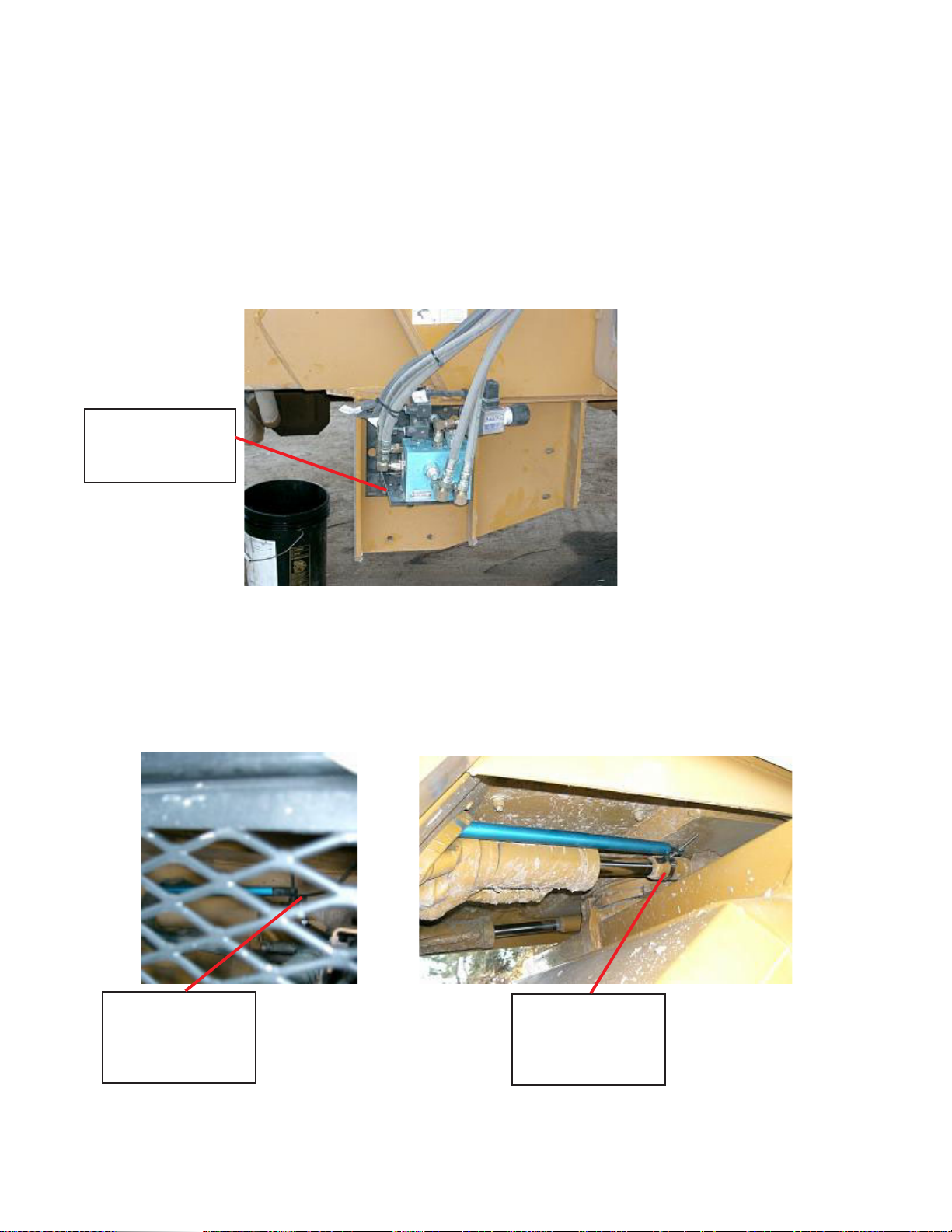
MOUNTING THE STEERING POSITION SENSOR ........................................................................... 2
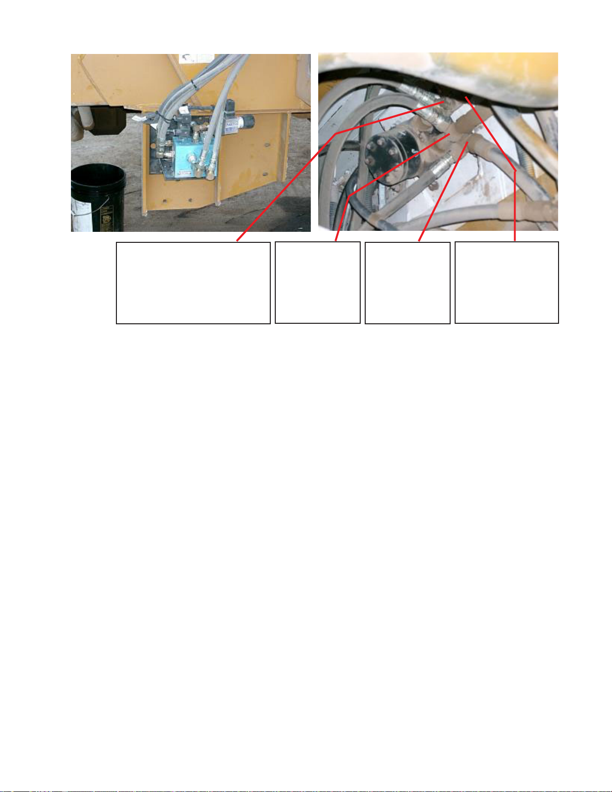
MOUNTING THE HYDRAULIC VALVE............................................................................................... 3
MOUNTING THE PRESSURE SWITCH ............................................................................................. 3
HOSE CONNECTIONS AND ROUTING ............................................................................................. 4
PRESSURE HOSE .................................................................................................................. 5
EXCESS FLOW HOSE ............................................................................................................ 5
TANK PORT HOSE..................................................................................................................5
LEFT STEER HOSE ................................................................................................................ 5
RIGHT STEER HOSE .............................................................................................................. 6
1903 with POWER BEYOND .............................................................................................................. 7
MOUNTING THE UNIVERSAL BRACKET.......................................................................................... 7
MOUNTING THE STEERING POSITION SENSOR ........................................................................... 7
MOUNTING THE HYDRAULIC VALVE............................................................................................... 8
MOUNTING THE COUNTERBALANCE VALVE, PRESSURE SWITCH & NEEDLE VALVE ........... 8
HOSE CONNECTIONS AND ROUTING ............................................................................................. 8
PRESSURE HOSE .................................................................................................................. 9
EXCESS FLOW HOSE ............................................................................................................ 9
TANK PORT HOSE..................................................................................................................9
NEEDLE VALVE HOSE ........................................................................................................... 9
CB TO LEFT STEER HOSE .................................................................................................. 10
CB TO RIGHT STEER HOSE................................................................................................ 10
B-PORT TO COUNTERBALANCE HOSE ............................................................................ 10
A-PORT TO COUNTERBALANCE HOSE ............................................................................ 10