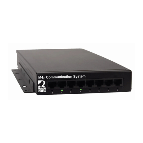
Raven 47800A-V Series User manual

Last Updated on February 10th,2022
REV1
PYRA RoIP/VoIP Interface User
Guide
Copyright © 2022 RAVEN ELECTRONICS CORPORATION 4655 Longley Lane #106, Reno Nevada 89502

2
Table of Contents
1Initial Setup............................................................................................................................................................3
1.1 Package Contents ........................................................................................................................................3
1.2 Connecting to the VoIP Interface..................................................................................................................3
1.3 Changing the Username and Password.......................................................................................................6
2Changing the IP Address of the VoIP Interface.....................................................................................................7
2.1 How to Change the Network Settings...........................................................................................................7
3Blade Setup...........................................................................................................................................................8
3.1 How to Change Individual Port Settings .......................................................................................................8
3.2 Pinout for the Analog 2-wire/4-wire Ports .....................................................................................................9
4How to Make a Bridge Group..............................................................................................................................10
4.1 Bridging two or more M4x Audio Channels Together .................................................................................10
5RTP Streaming....................................................................................................................................................11
5.1 RTP Streaming Audio from a Channel to Another RTP Device..................................................................11
6Blade-Link ...........................................................................................................................................................14
6.1 How to Connect Blades with Blade-Link Using Pyra Firmware...................................................................14
6.2 How to Connect Blades with a FlexGate Using Blade-Link ........................................................................18
7SIP Channel........................................................................................................................................................20
7.1 How to Associate an Analog Channel with a SIP Account..........................................................................20
8Saving the Configuration.....................................................................................................................................23
8.1 How to Save the Configuration of the VoIP Interface for Future Restores..................................................23
9Resetting the VoIP ..............................................................................................................................................24
9.1 How to Reset the VoIP to Have Default Settings through Hardware ..........................................................24
9.2 How to Reset the VoIP Interface to Have Default Settings through the Webpage......................................25
10 Firmware Updates...............................................................................................................................................26
10.1 How to Apply a New Firmware Update.......................................................................................................26
11 Troubleshooting the VoIP Interface.....................................................................................................................27
11.1 Why Can’t I Reach the Webpage? .............................................................................................................27
11.2 Why Am I Getting E&M Signaling One Direction but Not the Other Direction when Using Blade-Link?.....27
11.3 Why is my Blade restarting in a Constant Boot-Loop?................................................................................28

3
1 Initial Setup
1.1 Package Contents
•One Power Cable and Power Adapter
•One Mini Blade with VoIP Module (47800A-003-V or 47800D-003-V)
OR
•One 8-Port Blade with VoIP Module (47800A-XXXV or 47800D-XXXV)
1.2 Connecting to the VoIP Interface
To configure a Blade that has a VoIP interface in it, you will need the power supply sent with the unit as
well as a CAT 5 ethernet cable that is connected to your network. Figure 1-1 shows the front view of an
8-port Blade and Figure 1-2 shows the front view of a 2-port Mini Blade.
Figure 1-1: Front view of the 8-port Blade.
Figure 1-2: Front view of the 2-port Mini Blade.

4
1. Power up the Blade by plugging in the power supply to the back of the unit.
2. Plug in a CAT 5 Ethernet cable that is on your network into Port 7 (8-port Blade) or into Port 1 (2-
port Mini Blade). Refer to Figure 1-1 and 1-2 that shows the numbering of the ports. *If you
have multiple new blades to configure, connect only one at a time since it has the same static
IP of 192.168.50.65*
3. Confirm that once connected, a Link Status (Solid Green) and Link Activity (Blinking Red) LEDs
will begin to turn on.
4. On the PC used to connect to the VoIP interface, navigate to Control Panel > Network and
Internet > Network Connections. Choose the Ethernet adapter that is on your network and go
to Properties > Internet Protocol Version 4 (TCP/IPv4) > Properties.
5. Configure your network adapter with the following parameters. Please take note of your current
settings so that you can revert them after VoIP provisioning is finished.
IPv4 Address: 192.168.50.100
Subnet mask: 255.255.255.0
Default Gateway: [Leave Blank]
Preferred DNS server: [Leave Blank]
Secondary DNS server: [Leave Blank]
6. Open a web browser and type http://192.168.50.65/index.html in the Address bar to access the
PYRA Web Configuration. *Make sure it is html and not just htm when trying to connect*
7. A pop up will appear where you can type in the username and password that will look similar to
Figure 1-3 depending on the browser being used.
Figure 1-3: The pop up that will appear after successfully accessing 192.168.50.65 on the web
browser.

5
8. Enter the default Username: Admin and Password: Admin.
9. Figure 1-4 shows the “System Information”page that will be brought up once entering the
correct username and password.
Figure 1-4: The “System Information”page that will pop up once correctly connecting to
192.168.50.65 and entering the correct credentials.

6
1.3 Changing the Username and Password
1. Navigate to the “System” tab on the left panel, click the “Administration” in the drop down, and
it will look like Figure 1-5.
Figure 1-5: The “Administration” page where the username and password can be changed
2. Type in the new username, password, and the password again to confirm. Click the “Save
Changes” button to apply the new credentials.
3. If the username and password are changed, a pop will appear looking like Figure 1-6. If the
passwords do not match, it will look like Figure 1-7.
Figure 1-6: The popup that will appear confirming that the username and password was
changed.
Figure 1-7: The popup that will appear when the passwords typed in do does not match.

7
2 Changing the IP Address of the VoIP
Interface
2.1 How to Change the Network Settings
1. Navigate to the “Network Setup” page on the left side panel and it will look like Figure 2-1.
Figure 2-1: “Network Setup” web interface.
2. Enter in the network settings:
General:
Host: The host name can be changed to whatever you want. This name will be used
when configuring VoIP interfaces with Blade-Link that will be described later in the
document.
Domain: This field is not required. If you have a registered domain name that you want
to link to this VoIP interface, enter it here.
Connection Type: By default, it is set to the Static IP so you can choose the IP address on
your own. If you want the DHCP to find an address for you, choose Dynamic IP and click
the “Save Changes” button.
Static IP Address
Address: The new IP Address desired for the VoIP interface
Mask: Subnet mask
Default Router: The main Router/Gateway of your network
DNS Primary: The primary DNS server for you network if needed
DNS Secondary: The secondary DNS server for you network if needed
DNS Tertiary: The tertiary DNS server for you network if needed
3. Click the “Save Changes” Button at the bottom of the page once done. A pop-up will appear
asking if you want to restart the blade. Click “Yes”.
4. Once the Blade is restarted, wait 10-30 seconds for it to reboot, and enter the new IP into your
browser to make sure you are able to reach the webpage again.

8
3 Blade Setup
3.1 How to Change Individual Port Settings
1. Navigate to the “Blade Setup” page on the left side panel and
it will look like Figure 3-1.
2. Change the Individual Port Settings:
Port Configuration:
Select Existing Port: This is the port you are making changes to
Port Type: This auto populates. If you have a 2 channel 2-wire/4-wire module,
it will say 476-153
Module #: This auto populates when chosen the “Select Existing Port”
Port #: This auto populates when chosen the “Select Existing Port”
Port Name: This is where you can change the name of a port to have a specific
name (site name, equipment name, repeater name, etc).
Transmit Level (dB): The amount of gain that will be transmitted out of this port
Receive Level (dB): The amount of gain that will be adjusted to the Receive
audio on this port
Impedance 600 Ohm: By default, the receive impedance is set to 600 Ohm.
Unchecking the box will make it high impedance.
Audio Interface Type: Changes between 2-wire and 4-wire mechanisms.
Defaulted to 4-wire.
PTT Polarity: This defines the PTT polarity. This is defaulted to normally open
when unactive and makes a switch closure when active. Unchecking the box will
reverse this.
COR Polarity: This defines the COR input polarity. This is defaulted to normally
open when unactive and detects a switch closure when COR is inputted.
Unchecking the box will reverse this.
Dtmf Detect: Makes it so the M4x channel can detect DTMF and use those
numbers to dial out or patch interfaces together for special applications
Muting: Mutes either the Transmit or Receive audio when clicked.
Transmit Audio Delay (ms): The amount of time in ms that the audio will be
delayed when transmitting out this port. Max amount is 1000 ms.
PTT Hold-On (ms): The amount of time the PTT circuit is held-on for. Max
amount is 1000ms.
Channel Select Position: Used for special applications. Not required.
API Provides Ringback: Used for special applications. Not required.
Blade-Link IP and Associated Port: This is used for Blade-Link which is described
in Section 6.1 How to Connect Blades with Blade-Link Using Pyra Firmware
3. Click the “Save Changes” button, wait until the page
refreshes, and move onto the next port if needed.
Figure 3-1: “Blade Setup” web interface.

9
3.2 Pinout for the Analog 2-wire/4-wire Ports
Refer to Figure 3-2 and Figure 3-3 for the pinouts for the 153 modules. Note the E-Lead is COR input,
and the M-Lead is PTT output.
Figure 3-2: The RJ-45 connector for reference.
Figure 3-3: The pinout for the 153 modules.

10
4 How to Make a Bridge Group
4.1 Bridging two or more M4x Audio Channels Together
1. Navigate to the “Conferences” page on the left side panel and it will look like Figure 4-1.
Figure 4-1: “Conferences” web interface.
2. Type the name of the bridge being configured.
3. Select the ports that need to be bridged as shown in Figure 4-2.
Figure 4-2: Selecting the different ports to be added to the bridge.
4. Click the “Create”.
5. Check the Box labeled “Enable”.
6. Create more bridges if needed.

11
5 RTP Streaming
5.1 RTP Streaming Audio from a Channel to Another RTP Device
1. Navigate to the “Channel Setup” page on the left side panel and it will look like Figure 5-1.
Figure 5-1: “Channel Setup” web interface.
2. Type the name of the RTP stream.
3. Select “RTP Channel”under Channel Type and click “Create”.
4. A pop-up will appear labeled “Account Configuration”as seen in Figure 5-2. Fill out the RTP
settings:

12
Figure 5-2: The “Account Configuration” pop-up for RTP Streams.
RTP peer: IP Address of the other device in the RTP Session
Codec: The type of CODEC (G.711 µ-law should be used unless specified).
Tx/Rx Ports: An even number used for the RTP Ports (The same number can be used for both Tx/Rx. If
they are different, make sure the Tx of one blade matches the Rx of the other blade and vice-versa)
Multicast This is used when there are more than two devices in the network that need to communicate
with each other over IP. The RTP peer would then be pointed towards a Multicast IP Address (224.0.0.0 to
239.255.255.255).
Multicast TTL: The Multicast Time-To-Live, which is number of times the data can pass through a router. If
the TTL field reaches 0 before the destination, the data is discarded. Used only for Multicast.
Silence Suppression Trigger: The Raven will only send audio packets on VOX if set to “Enable”. If set to
“Disable”, packets will always be sent.
Noise Suppression: This helps with removing background noise within the signal. Not required.
Firewall Keep alive: The Raven sends out keep-alive packets when enabled. Not required.
Active Channel This activates the RTP session if clicked “Enabled” (The channel can also be
enabled/disabled by the checkbox after it is created).

13
5. Click the “Save” button and the RTP Channel will be created.
6. Navigate to the “Conferences” page on the left side panel.
7. Name the conference that will link the RTP stream with a port.
8. Click the name of the RTP channel and one of the ports that the RTP stream will be directed
towards as shown in Figure 5-3.
Figure 5-3: Selecting the RTP channel and one of the ports.
9. Click the “Create” button and the conference will be shown.
10. Click the “Enable”checkbox to enable the conference between the RTP stream and the port.

14
6 Blade-Link
6.1 How to Connect Blades with Blade-Link Using Pyra Firmware
In this example we are connecting an 8-port Blade to a 2-port mini blade. The IP Address of the 8-port
Blade is 192.168.50.64 and the IP Address of the 2-port Blade is 192.168.50.80. The 8-port Blade will be
the dedicated server for the Blade-Link. The same steps can be followed when connecting an 8-port to
another 8-port or a 2-port to another 2-port.
1. Navigate to the “Blade Setup” page on the left side panel on the dedicated Blade-Link Server
webpage (in this example it is 192.168.50.64).
2. Under “Blade Configuration” and “Enter Remote Gateway Address”, there is a spot to enter an
IP Address followed by a Port number. This is shown in Figure 6-1. If there is no Port number
entered, it will automatically be defaulted to Port 8676.
Figure 6-1: Example of entering the non-server IP address on the
3. Enter the IP Address/Port of the non-server Blade. In our example, the 8-port Blade is our
dedicated Blade-Link Server so we will enter 192.168.50.80 for the Mini-Blade. **Do not go
onto the non-server “Blade Setup” webpage and enter the IP Address/Port for the Dedicated
Server. This will not make Blade-Link work. Once the IP Address is entered for a Blade-Link,
you do not need to do it on the other side.**
4. Click the “Add >>” button and it will be populated under “Gateway Address List”.
5. Click “Save IPs” and it will restart the Blade. *The non-server blade does not need to be
restarted*
6. Once rebooted, log back in and navigate to “Blade Setup” again.
7. At the bottom of the page, the information from the non-server Blade will be populated. In our
example, it would be the 2-port mini-Blade. This is shown in Figure 6-2.

15
Figure 6-2: The information of the non-server Blade will be populated once a reboot has been
performed.
8. Click the name/IP of the Blade you are connecting with Blade-Link. On the right is the physical
Port of the M4x channel of that Blade. Since it is a Mini Blade, it will only have the option for
Port 2 as seen in Figure 6-2.
9. Click “Save Changes”.
10. Navigate to “Blade Setup” on the non-server webpage.
11. Under “Blade-Link IP and Associated Port” the server Blade will be populated. Since it is an 8-
port Blade, there will be more options for the Ports as seen in Figure 6-3. In this example, Port 1
was chosen.
Figure 6-3: The information of the server Blade will be populated and will have Port 1-7 and Port
8 as options to choose from.
12. Click the “Save Changes” button.

16
13. Navigate to the “Bladelink Status” page on the left side panel on both the blades. The two
blade’s information now should be seen under “Local Blade” and “Remote Blade”. The “Local
Blade” is the blade that is associated with that webpage. The “Remote Blade” would be the
other blade that is not associated with that webpage. This is reversed if you look at the other
blade’s webpage. This is shown in Figure 6-4. The Green LED on the “Remote Blade” indicates
that it is properly linked, and the unit is not down.
Figure 6-4: The “Bladelink Status” page showing the different Local Blades and Remote blades
depending on which website you are looking at.
14. Confirm when there is a COR input in the ports chosen in steps 8 and 11, there is a PTT on the
opposite side. Figures 6-5 and 6-6 shows Blade-Link properly working. **In order for audio to
send between the two blades, you need an RTP stream. This is outlined in Section 5.1 RTP
Streaming Audio from a Channel to another RTP Device. **

17
Figure 6-5: COR input on Port 1 on the sever Blade and PTT output on Port 2 on the non-server Blade
indicating Blade-Link is working.
Figure 6-6: COR input on Port 2 on the non-sever Blade and PTT output on Port 1 on the server Blade
indicating Blade-Link is working.

18
6.2 How to Connect Blades with a FlexGate Using Blade-Link
In this example we are connecting a FlexGate to an 8-port Blade. The IP Address of the 8-port Blade is
192.168.50.64 and the IP Address of the FlexGate 192.168.50.82. The FlexGate needs to be the
dedicated server for the Blade-Link. It is assumed that the user configuring this type of Blade-Link has
knowledge of how the FlexGate already works and has the FlexGate setup. If not, please refer to the
Raven FlexGate Comprehensive Guide in the manual section first. *The blade-link will not show up
under the VoIP’s interface webpage as a “Remote Blade”. It also will not show up under a selection
when configuring the individual ports under “Blade Setup”. The conference for the RTP channel will
determine where the blade-link signaling will be directed towards*
1. Navigate to the FlexGates webpage and log in.
2. Click on the “Blade Link” section on the left side panel to create the new interface and will look
like Figure 6-7.
Figure 6-7: The FlexGate configuration page for Blade-Link.
3. Fill out the Blade-Link settings:
Name: This will be the name of the Blade-Link that will show up under the endpoints listings.
Remote blade IP address: The IP Address of the blade that has a VoIP module and the Pyra
firmware
Remote blade control port: The control port that will be associated with this blade-link. The
same port number needs to match the remote blade’s port number.
Configuration: Single Channel is for 2-port Mini Blades and Multi Channel is for 8-port Blades.
Bind To Address: The FlexGate can have multiple IP addresses, so choose the IP address that is
on the same network that can reach the remote Blade.

19
4. Click the “Submit” button and the page will refresh to look like Figure 6-8.
Figure 6-8: Once the “Submit” button is clicked, the webpage will be refreshed to show the
different channels that can be selected for an RTP stream.
5. Create the RTP channels associated with the Blade-Link by entering a name, the Rx and Tx Ports
to match with the Tx and Rx ports on the VoIP interface, checking the box if COR is required for
the blade-link, and clicking the enable button. *The RTP Channels does not correspond to the
individual ports. Do not skip unused channels since it can cause problems loading in the
settings during FlexGate restarts. If the checkbox for COR is not checked, it will operate in VOX
mode. This is good for radios that do not provide the COR on the input side of the VoIP
interface, but do require a PTT for the output *
6. Navigate to the “Patches” page on the FlexGate webpage and add the RTP channel names
created with the M4x Blade Audio Channels. *If you do not have your M4x audio channels
already setup, refer to the FlexGate Comprehensive Guide*

20
7 SIP Channel
7.1 How to Associate an Analog Channel with a SIP Account
In this example we will have an 8-port blade using the Pyra firmware and a dedicated SIP server. The 8-
port blade will have an IP address of 192.168.101.65 and the SIP server will have the 192.168.101.100 IP
address. The blade and the SIP server need to be on the same network in order for it to register. The EXT
for this SIP will be 1234.* It is assumed the EXT 1234 under the SIP server is already setup and is ready
to connect to this blade. The analog channel will be unable to initiate a SIP call, but an external device
connected to the same SIP server such as a SIP phone or Raven’s IP Deskset can start a call*.
1. Navigate to the “Channel Setup” page on the left side panel and it will look like Figure 7-1.
Figure 7-1: “Channel Setup” web interface.
2. Type the name of the SIP channel.
3. Select “SIP Channel” under Channel Type and click “Create”.
4. A pop-up will appear labeled “Account Configuration” as seen in Figure 7-2. Fill out the SIP
settings:
This manual suits for next models
3
Table of contents
Other Raven Network Hardware manuals
Popular Network Hardware manuals by other brands

PulseWorx
PulseWorx PW513 Installation guide and owner's manual

Digi
Digi Connect EZ Mini user guide

Teletronics International
Teletronics International EzBridge Configuration manual

Nokia
Nokia IP290 - Security Appliance installation guide

Allied Telesis
Allied Telesis AT-TN127-A Specifications

Speco
Speco N8 user guide

Marshall Amplification
Marshall Amplification VSC-100 user manual

Altronix
Altronix TROVE PLUS T2M7LXK1V installation guide

TP-Link
TP-Link AC3200 installation guide

Advantech
Advantech EKI-1361 user manual

Eaton
Eaton SPD150i Technical Specifications and Installation Guidelines

ADTRAN
ADTRAN NetVanta E1/FE1 Network Interface Module quick start guide