M7 GX Technical Manual
7
Raveon Technologies Corp.
7.1. GPS Additional Commands to Configure GPS and Tracking Features
The following commands are unique to the –GX version of the M7. When you execute any of these
commands, the new parameter is automatically stored in EEPROM.
Command Command Descri tion Parameters Default
GX Dis lay GPS settings. how an overview of the current GP features and
configurations in the M7 GX. - -
GPS GPS O eration Mode. Read/ et the GX version’s Operating mode. 0 - 6 1
GPS&F
Reset all GPS (-GX version) arameters. et the GX version’s Operating
mode to GP mode 4, and sets all GP parameters to factory defaults. It
does not erase frequency or other radio-related parameters.
- -
IDLERATE IDLE TX Interval. et the number of seconds between position transmissions
when the unit is idle (has not moved more than TRIGDX meters).
0-9999
seconds 10
KEYPHRASE
Privacy Security Key Code. et the privacy key for this device. It must be
the same key as used on all other Raveon products in your system. It
secures radio transmissions from unauthorized reception. et it to 0 to disable
security encryption of data.
2-16 A CII
characters. “RAVEON”
PREFIX
ID Prefix. et an ID prefix. The prefix is 1-8 characters that will be put in
front of the ID when reporting an ID as a waypoint name. A dash means no
prefix. Default is a capitol letter V.
1-8 A CII characters
et it to “0” for no
prefix.
V
SLOTTIME TDMA Slot duration. Configure the width of a TDMA slot. 50m increments.
50 - 1000 200
SLOTNUM TDMA Slot Number. Configure the slot number that this radio will use to send
its data in. 1-9999 The MYID of
the unit
TRIGBITS
I/O Change Re orting. Which bits are used as transmission triggers. This is
a HEX number. Bit 0 is IN0, bit 1 is IN1…. 0-FF 0
TDMATIME
Set/read TDMA Frame time. The length of one TDMA time frame, in
seconds. M7’s may transmit once per frame, and only in their preset time-
slot.
1-3599 10
TRIGPOL
Polarity of the in ut bits. 0 = normal active high operation(causes unit to
transmit when it goes high), 1 = Inverted, active low. This is a HEX number.
Bit 0 is IN0, bit 1 is IN1….
0-FF 0
Active high
TRIGEX
Re ort on change. ets which input bits cause a report on change. If a
particular bit is a 1, then it will trigger a report when it changes. The input bit
must also be enable with the TRIGBIT . This is a HEX number. Bit 0 is IN0,
bit 1 is IN1…
0-FF 0
TRIGDX
Distance trigger. et a distance (in meters) threshold beyond-which the unit
will transmit its position and status. If set to 0, the unit always reports at the
TXRATE. If set to an distance greater than zero, then the unit reports at the
TXRATE intervals if it has moved this distance since the last report. If it has
not moved, it will still report its position, but at the rate set by IDLERATE. If
IDLERATE is set t 0, then the unit will not report its position when not moving.
0-999 0
TRIGSPEED
S eeding Re ort. et a speed (in kilometers/hour) threshold above-which
the unit will begin reporting its position and status. et to 0 to disable this
feature.
0-999 0
TXRATE
GPS Re ort Rate. et number of seconds between GP reports. This is
also the rate at which the internal GP will measure position, speed, etc.
Even if the unit is not moving, the GP periodically measures position and
speed to determine if it has triggered a speed or position transmission.
1 - 9999 10
7.2. Factory Default Settings
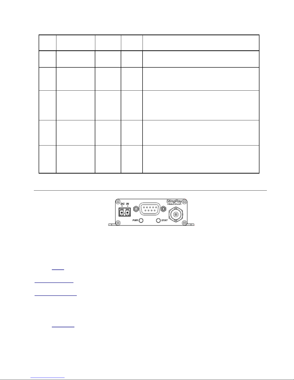
For the UHF M7 GX model RV-M7-UC-GX, the factory defaults GP settings are:
Radio channel 1 .................464.500 MHz Slot Number............................The same ID
G S Mode ............................4 (G S display) ID refix ..................................V
Over-the-air baud rate:..........4800 baud, 2-level I/O Change reporting ..............0, off
Serial port.............................. 4800 N/8/1 roximity Alert.........................0, off
Hardware flow control ...........Off Security KEY...........................RAVEON
RF ower Output ..................5 watts osition report interval ...........10 seconds
Channel number ...................1