5
ADANGER: ELECTROCUTION
OR ELECTRICAL SHOCK RISK.
DISCONNECT ELECTRICITY BEFORE
WORKING ON PUMP, OR SHOCK, BURN
OR ELECTROCUTION CAN RESULT.
Always disconnect pool pump power at the circuit breaker
before servicing the pump. Death or serious injury to
service people, pool users or others due to electric shock
could result from failure to avoid the high danger risk.
ADANGER: For continued protection against possible
electrical shock, this unit is to be mounted to the base in
accordance with the installation instructions.
NOTE: Always turn o all power to the pool pump before
installing the cover or working on any suction outlet.
NOTE: This pump operates with electrical voltage, and
can generate both vacuum and pressure in the water
system. When properly wired and plumbed, this pump
will operate in a safe manner.
ACAUTION: This pump is for use with permanently
installed pools and may also be used with hot tubs and
spas. Do not use with storable pools unless the pump
is protected by a factory-installed double-insulated
enclosure. A permanently-installed pool is constructed
in or on the ground or in a building such that it cannot
be readily disassembled for storage. A storable pool is
constructed so that it may be readily disassembled for
storage and reassembled to its original integrity.
AWARNING: To reduce the risk of electrical shock,
replace any damaged electrical cord immediately.
AWARNING: Never work on the pump while it is
running or the power is still connected. High voltage
and cause serious or fatal injury. A suitable ground
fault interrupter (GFCI) should always be installed at
the power supply source of this unit. Article 681-31 of
the NEC requires that a GFCI be used if this pump is
used with a storage pool. Be sure to ground the motor
before connecting to electrical AC power source. Failure
to ground the motor can cause serious or fatal electrical
shock hazard. DO NOT ground to a gas supply pipe line.
AWARNING: A pool or spa pump must be installed
by a qualied pool and spa service professional in
accordance with the National Electrical Code and
all applicable local codes and ordinances. Improper
installation may cause and electrical hazard which could
result in death or serious injury to pool users, installers,
or others due to electrical shock, and also cause
property damage.
AWARNING: Pumps are not a substitute for properly
installed and secured pool drain covers. An ANSI/ASME
A112.19.8 approved anti-entrapment drain cover must
be used for each drain. Pools and spas should utilize a
minimum of 2 drains per pump. If a drain cover becomes
loose, broken, or is missing, close the pool or spa
immediately and shut o the pump until an approved
anti-entrapment drain cover is properly installed with
the manufacturer's supplied screws.
NOTE: Always turn o all power to the pool pump before
installing the cover or working on any suction outlet.
ACAUTION: Elevated water temperature can
be hazardous. The U.S. Consumer Product Safety
Commission has these guidelines:
1. Spa water temperatures should never exceed 104°F
(40°C). A temperature of 100°F (38°C) is considered
safe for a healthy adult. Special caution is suggested
for young children.
2. Drinking of alcoholic beverages before or during spa
or hot tub use can cause drowsiness which could
lead to unconsciousness and subsequently result in
drowning.
3. Pregnant Women Beware! Soaking in water over
102°F (39°C) can cause fetal damage during the rst
three months of pregnancy resulting in the birth of a
brain-damaged or deformed child.
4. Before entering the spa or hot tub, users should
check the water temperature with an accurate
thermometer; spa or hot tub thermostats may err
in regulating water temperatures by as much as 4°F
(2.2°C).
5. Persons with a medical history of heart disease,
circulatory problems, diabetes, or blood pressure
problems should obtain a physician’s advice before
using pools or hot tubs.
6. Persons taking medications which induce
drowsiness, such as tranquilizers, antihistamines,
or anticoagulants, should not use spas or hot tubs.
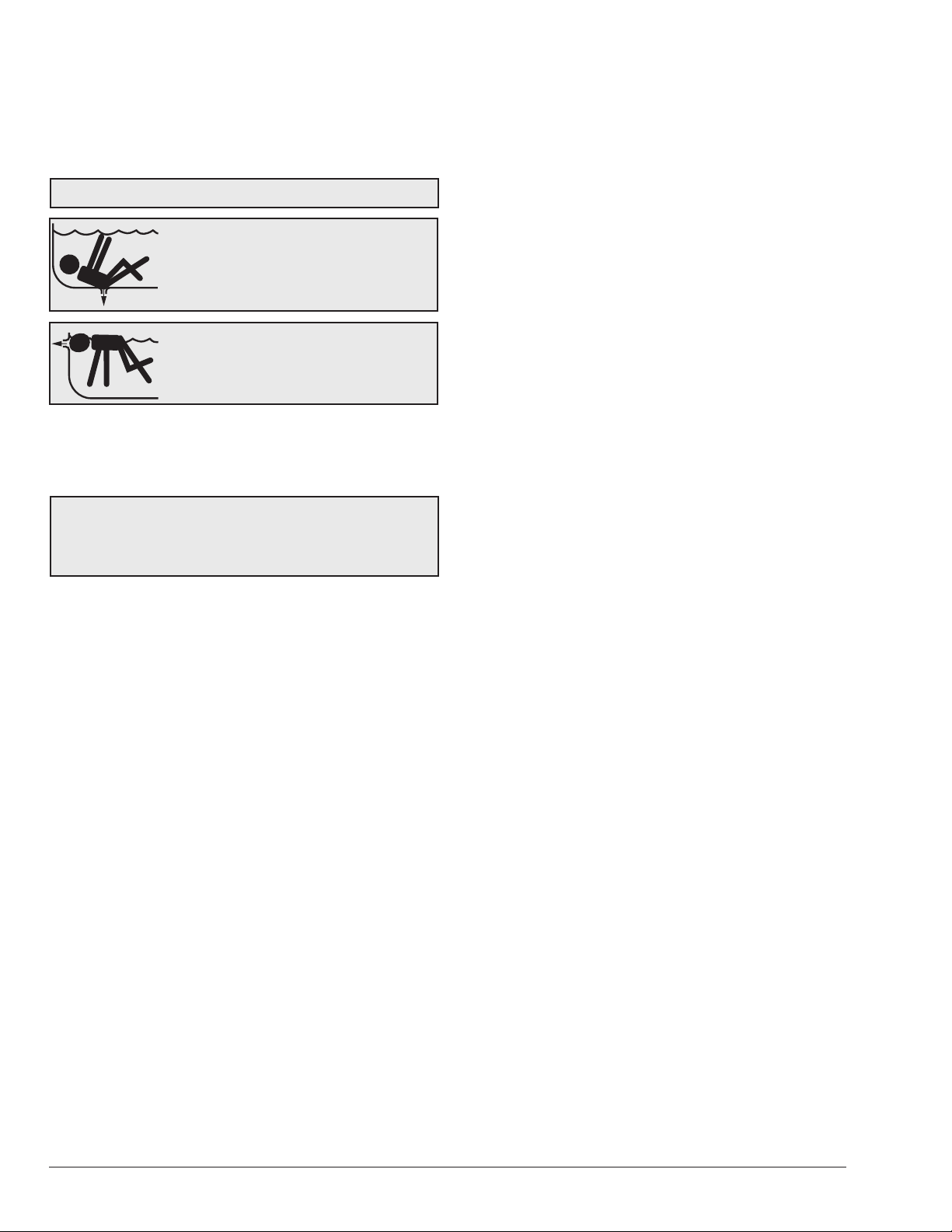
AWARNING: Pump suction is hazardous and can
trap and drown or disembowel bathers. Do not use or
operate swimming pools, spas, or hot tubs if a suction
outlet cover is missing, broken, or loose.
ADANGER: Hazardous suction can
trap hair or body parts, causing severe
injury or death. Do not block suction.
AWARNING: Risk of Electric Shock. Connect only
to a branch circuit protected by a ground-fault circuit-
interrupter (GFCI). Contact a qualied electrician if you
cannot verify that the circuit is protected by a GFCI. The
unit must be connected only to a supply circuit that is
protected by a ground-fault circuit-interrupter (GFCI).
Such a GFCI should be provided by the installer and
should be tested on a routine basis. To test the GFCI,
push the test button. The GFCI should interrupt power.
Push the reset button. Power should be restored. If
the GFCI fails to operate in this manner, the GFCI is
defective. If the GFCI interrupts power to the pump
without the test button being pushed, a ground current
is owing, indicating the possibility of an electric shock.
Do not use this pump. Disconnect the pump and have the
problem corrected by a qualied service representative
before using.