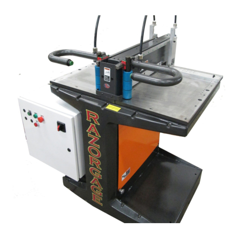
Razorgage Cyclone RazorOptimal User manual

Cyclone RazorOptimal User Manual
2 | P a g e
Technical Services, Inc.
Table of Contents
General Safety Rules for Woodworking Machinery...............................................4
Safety Rules for Cut Off Saw ..................................................................................6
Arrival Inspection ...................................................................................................7
Installation .............................................................................................................8
Leveling.....................................................................................................9
Anchoring .................................................................................................9
Infeed/Outfeed Tables ............................................................................10
Electrical Power Connection....................................................................10
Electrical Interface Connections ..............................................................11
Air Supply Connection.............................................................................12
Pneumatic Connections...........................................................................12
Dust Collection........................................................................................13
Setup Procedure ...............................................................................................14
Saw Capacity.....................................................................................................21
General Operation ............................................................................................22
Machine Adjustments.......................................................................................26
Lockout/Tagout Points ............................................................................27
Saw Feed Flow Controls ..........................................................................28
Saw Stroke Distance................................................................................29
Saw Blade Speed.....................................................................................30
Horizontal Clamps Pressure Regulator ....................................................30
Horizontal Clamps Flow Controls ............................................................31
Vertical Clamp Pressure Regulator .........................................................31
Vertical Clamp Flow Controls ..................................................................32
Vertical Clamp Stroke Distance ...............................................................33

Cyclone RazorOptimal User Manual
3 | P a g e
Technical Services, Inc.
Guide Rollers...........................................................................................33
Back Fence ..............................................................................................34
Squaring Back Fence to Saw Blade ..........................................................35
Pusher Lift Height....................................................................................36
Maintenance.....................................................................................................37
Lubrication..............................................................................................37
Saw Blade Access ....................................................................................38
Changing Out Saw Blade .........................................................................38
Replacement Parts List............................................................................39
Troubleshooting ...............................................................................................41
Electrical Schematics ...............................................................................41
Pneumatic Schematics ............................................................................45
Troubleshooting Guide............................................................................46
VFD Faults...............................................................................................50
Troubleshooting Reference Pictures........................................................51
Troubleshooting E-Stop Faults.................................................................53

Cyclone RazorOptimal User Manual
4 | P a g e
Technical Services, Inc.
General Safety Rules for Woodworking Machinery
WARNING
The operator must thoroughly read and
understand this manual before operating the
saw or starting any servicing. All safety and
warning instructions should be followed.
This manual must be available to all
operators.
1. For your own safety, read the operation manual carefully. Know your machine. Learn its
applications and limitations, and any hazards specific to this machine. All personnel should be
trained in the operational procedures and received safety instruction before operating this
equipment. If you have not received proper training in the use of this machine, DO NOT
OPERATE THIS MACHINE, damage to the equipment or injury to the operator is possible.
2. This machine should not be operated without all of the guards in place and safety devices in
operation. Removal of any guards or disabling any of the safety devices may result in damage
to the equipment or injury to the operator. If any of the guards or safety devices are missing,
damaged or not working properly, DO NOT OPERATE THIS MACHINE, notify your supervisor
immediately.
3. If the operator has any safety concerns or questions regarding the operation of this equipment,
DO NOT OPERATE THIS MACHINE, the machine should be locked out and your supervisor
notified immediately.
4. All Lock Out/Tag Out procedures must be followed before servicing or adjusting this equipment.
If you have not received proper training in the Lock Out/Tag Out procedures for this machine,
DO NOT OPERATE THIS MACHINE, damage to the equipment or injury to the operator is
possible.
5. In case of any equipment malfunction or jam the machine should be powered off and locked out
before clearing any materials from the operational areas of this machine. Once cleared the reset
procedures need to be followed when powering up the equipment. At no time should any of the
machine control systems including electrical, hydraulic or pneumatic circuits be manually
overridden.
6. Check machine for damaged parts. Before continued machine use any damaged guard or part
must be carefully checked for proper operation of its intended function. Check all moving parts
for proper alignment, check for binding of moving parts, breakage of parts, proper secure
mounting, and any other condition that may affect machine operation. Guards or other parts that
are damaged must be properly repaired or re-placed.
7. Machine must be properly grounded.

Cyclone RazorOptimal User Manual
5 | P a g e
Technical Services, Inc.
8. Maintain and clean machine at recommend intervals. Intervals may need to be adjusted due to
work load or material type to keep machine in top condition. Follow instructions for lubrication,
setup, and changing accessories
9. Disconnect machine from power source before, changing accessories, or any servicing activity.
10. Avoid accidental starting. Make sure switch is in the off position before connecting to power.
11. Remove any tools or loose objects from work surface of machine. Make sure any tools used for
adjustment or maintenance are removed from machine before machine is restarted. Make a
habit of scanning for tools and scraps every time the machine is started.
12. Keep work area clean. Cluttered work areas and workbenches increase the likelihood of an
accident.
13. Do not use in dangerous environments. Do not use machine in damp or wet locations, or expose
them to rain. Keep work area well illuminated.
14. Keep children away. All visitors should be kept at a safe distance from work area.
15. Make workshop childproof, with padlocks, master switches, or by removing starter keys.
16. Do not force the machine. It will function better and safer at its designed rate.
17. Use the right tools. Do not force the machine or attachments to do a job for which they were not
designed. Contact the manufacturer or distributor if there is any question about the machine’s
suitability for a particular job.
18. Use only recommended accessories. Consult the operation manual for recommended
accessories.
19. Wear proper apparel. Avoid loose clothing, gloves, neckties, rings bracelets, or jewelry which
could be tangled in moving parts. Keep long hair contained to prevent entanglement. Non-slip
footwear is recommended.
20. Always wear safety glasses.
21. Secure the work piece.
22. Keep proper footing and balance at all times.
23. Do not use machine while under the influence of drugs, alcohol, or any medication.
24. Always wear a face mask or dust mask if operation creates excessive dust or chips. Always
operate machine in a well-ventilated area and provide proper dust removal.
25. Never leave machine running unattended. Turn power off. Do not leave machine until it comes
to a complete stop.

Cyclone RazorOptimal User Manual
6 | P a g e
Technical Services, Inc.
Safety Rules for Cut-off Saw
WARNING
The operator must thoroughly read and
understand this manual before operating the
saw or starting any servicing. All safety and
warning instructions should be followed.
This manual must be available to all
operators.
1. Read and understand the operation manual before operation.
2. Keep hands away from the cutting area.
3. Before making any adjustments disconnect all power sources including electrical and
pneumatic.
4. Minimum air pressure is 50 psi, DO NOT operate saw if minimum air pressure is not available.
Normal working pressure is 80psi.
5. At the start of each work session turn on saw and cycle the saw and check for normal
operation of top clamp and blade advance cylinders. Turn off saw and as the motor slows and
comes to a stop check for correct rotation direction compared to arrow indicator.
6. Do not cut warped wood; work piece should lay flat on table without rocking.
7. Use infeed and outfeed supports when cutting long work pieces.
8. Set top clamp to minimum close height for material being processed.
9. Short trim scraps should only be removed by pushing them out with a scrap piece and NOT
with hands.

Cyclone RazorOptimal User Manual
7 | P a g e
Technical Services, Inc.
Arrival Inspection
WARNING
The operator must thoroughly read and
understand this manual before operating the
saw or starting any servicing. All safety and
warning instructions should be followed.
This manual must be available to all
operators.
The Cyclone Optimal ships with two items a pallet and a crate. The saw will be secured to a pallet. The
RazorGage positioner, tables, legs, and tower control cabinet will be in the crate. Unpack the saw
ensuring that all parts are present and free from damage. If any parts are missing or damaged contact
your local distributor immediately. Do not assemble or attempt to operate saw without all components
present and in undamaged condition.

Cyclone RazorOptimal User Manual
8 | P a g e
Technical Services, Inc.
Installation
WARNING
The operator must thoroughly read and
understand this manual before operating
the saw or starting any servicing. All safety
and warning instructions should be
followed. This manual must be available to
all operators.
Install saw with enough free space to conveniently allow workpiece to be brought into saw. If infeed
and/or outfeed tables are required allow room for such. The floor should be a flat non-slip surface. The
saw will be more stable if bolted to floor. After locating the saw use leveling feet to adjust level of saw
table. Place level on saw table and adjust feet to bring table into level position.

Cyclone RazorOptimal User Manual
9 | P a g e
Technical Services, Inc.
Leveling
To ensure product moves freely through the saw system, it is important to level the saw. After the saw
has been located the saw can be leveled. Place the level on top of the saw adjacent to the back fence
to check for level side-to-side. To check level front to back place level on the saw blade opening. Use
the jack bolts on the mounting feet to make the adjustments to saw level. It is important that once the
saw is level to check that all four mounting feet are sharing the weight of the saw. Otherwise the saw
will be unstable.
Anchoring
After saw is leveled, it is recommended that the saw is bolted down to the floor. This will improve stability
and help keep the saw system components aligned to each other. The saw has four mounting feet
located on the corners of the saw. Recommend using 3/8” x 12” anchor bolts.

Cyclone RazorOptimal User Manual
10 | P a g e
Technical Services, Inc.
Infeed/Outfeed Tables
The Cyclone RazorOptimal comes with table attachment brackets for mounting the infeed and outfeed
tables. Use the diagram below to first bolt the table attachment bracket to the saw and then attach the
table. After attaching the tables to the saw make sure to level them. There are leveling adjustment bolts
on the table legs and also on the table attachment brackets shown below.
Electrical Power Connection
WARNING
The operator must remove from and lock out
all power sources to saw before servicing or
connecting power.
The saw has been factory wired to the requested voltage before shipment. The saw power requirements
are either 208 / 230 VAC 3φ 30Amps OR 480 VAC 3φ 20Amps. The RazorGage tower requires a
separate 120V 1φ 10A supply. Check that your supply lines match the labeled voltage and the circuit
protection and wire gauge is adequate. Connect wires to the disconnect inside the electrical enclosure
as shown in pictures below.
Table of contents
Other Razorgage Saw manuals


