RC Guys Super Decathlon ARF User manual


TableofContents
PartsNeededtoCompleteKit ….. page01
TailWheelAssemblyInstallation ….. page02
StabilizerInstallation ….. page03
FinInstallation ….. page04
Elevator&RudderHingeInstallation ….. page05
RudderControls ….. page06
ElevatorControls ….. page08
MainWheelAxelInstallation ….. page09
WheelPantInstallation ….. page10
MainLandingGearInstallation ….. page12
SideDoorInstallation ….. page13
AileronHingeInstallation ….. page13
AileronServoInstallation ….. page14
WingStrutAssembly ….. page16
EngineInstallation ….. page19
CowlInstallation ….. page21
FuelTankInstallation ….. page23
Top&SideWindowInstallation ….. page24
FrontWindshieldInstallation ….. page25
RadioSetUp ….. page26
ControlSurfaceThrow ….. page26
OptionalTailSupportFlyingWires ….. page27

PartsYouWillNeedToCompleteKit
ÿ 1RudderServo(minimum70oz.torque)andmountinghardware
ÿ 1LargeRudderServoArm
ÿ 1or2ElevatorServo(minimum70oz.torque)andmountinghardware
ÿ 2AileronServos(minimum70oz.torque)andmountinghardware
ÿ 1ThrottleServo(minimum40oz.torque)andmountinghardware
ÿ 1or236inchElevatorServoExtension
ÿ 218inchAileronServoExtensions
ÿ 1“Y”ExtensionforAilerons
ÿ 1Engine2.5to4.0hp: 901602strokeglow
1202704strokeglow
2340ccgas
ÿ 1RadioTransmitter(minimum5channels)
ÿ 1Receiver
ÿ 1ReceiverBattery
ÿ 1SwitchHarness
ÿ 13½inchAluminumSpinner
NOTES:Loctiteeverythingthatdoesn’tneedtoberemovedoradjustedoften.
TestfitallTNutstoallowboltstobeeasilystartedbyhandandavoidcrossthreads.AstripedTNutis
difficulttoreplace.
1

TailWheelAssemblyInstallation
Collecttheseparts.
ÿ 1factoryassembledtailwheelbracket
ÿ 2 woodscrews
NOTE:Theextrapartinthebag(flatbarwith4holes)isforanalternatemethodofattachmentoftheTailWheel
Springs.
Collectthepreassembledtailwheelbracketandhardware.
PositiontheTailWheelAssemblyovertheFuselageandmarkthrough
theholes.
DrillpilotholesandsecurethetailwheelassemblytotheFuselage
usingthesuppliedhardware(2xwoodscrews).
HINT:UsethinCAtohardenallscrewholesintowoodandbalsa
afterthescrewhasbeenthreadedinandtakenbackout.
NOTE:TailWheelSpringsareinstalledaftertheRudder.
2

StabilizerInstallation
Collecttheseparts.
ÿ 1stabilizer
ÿ 1fin
Installthe2MainWingsusingtheAluminumWingTube.Ifitfitstoo
tightuse some600gritSandPaper.
PositiontheStabilizerovertheFuselageandcenteritusingarulerand
levelwiththemainWings.
HINT:Useatapemeasureorstringtomakesurethedistancefromthe
nosetoeachStabilizertipisthesamesothatitisalignedsquare.
Usingascribeorpen,carefullymarkalongthesidesoftheFuselage.
RemovethecoveringjustinsidethesemarksusingasharpXactoknife.
HINT:Useasmallamountofheatfromaheatgunwhenremoving
anycovering.
NOTE:BeforegluingtheStabilizertestfittheRudder.Ifyousee
spacebetweenthetopoftheStabandtheRudder,glueaspacer
undertheStabtofillthegap.Youmayalsohavetosandthefront
“key”oftheRuddersoitsitsallthewaydown.
RepositiontheStabilizerovertheFuselageandwhensatisfiedwith
thefit,glueitinplaceusingEpoxy.
3

FinInstallation
PositionthefinovertheFuselageandscribeamarkalongtheStabilizer
sides.
RemovethecoveringontheStabilizerjustinsidethesemarks.
RepositionthefinontheStabilizerandwhensatisfiedwiththefit,
glueinplaceusingEpoxy.Useasquaretoholdthefin90degreesto
theStabilizeruntiltheEpoxydries.Youmaywanttotapeitinplace.
NOTE:WipeawayanyexcessEpoxyusingdenaturedalcohol.
HINT:UseabeadofCanopyGluetofilljoints.Itdriesclear.
4

Elevator&RudderHingeInstallation
PositionandglueinplaceusingEpoxyallhingepointsintothefactorypredrilledholesinthe2Elevatorhalves.Donot
gluethemintotheStabilizerorfinatthistime.
NOTE:Checkthatthehingesareoperatingintheproperdirectionbeforethegluedries.Youmaywanttoplacea
smalldropoflightoilonthehingepinssothegluewillnotsticktothem.
HINT:GorillaGlueisalsogoodforgluinghingesbecauseitexpandstofillthegaps.
Ifusingengineweighinglessthan3lbs,youmaywanttopositiontheElevatorServoontheServoTrayratherthanatthe
rearoftheFuselageforbetterbalance.
YoucanusetheoptionalElevatorJoinerifyouonlywantjustoneElevatorServo,eitherontheServoTrayorattherear
oftheFuselagebelowtheStabilizerusingtheappropriatepushrod.TestfittheElevatorhalvesbeforegluingthehinges.
IftheyarenotinalignmentremoveandbendtheElevatorJoiner.
5

RudderControls
Collecttheseparts.
ÿ 1 rudderServoandmountinghardware(minimum70oztorque)
ÿ 1 rudderwirecable
ÿ 4 cablecrimpfittings
ÿ 4 cableclevises
ÿ 4 cableclevisnuts
ÿ 2 controlhorntrumpetbases
ÿ 1 trumpetscrew
ÿ 2trumpetclevises.(blackplastic)
ÿ 2tailwheelsteeringsprings
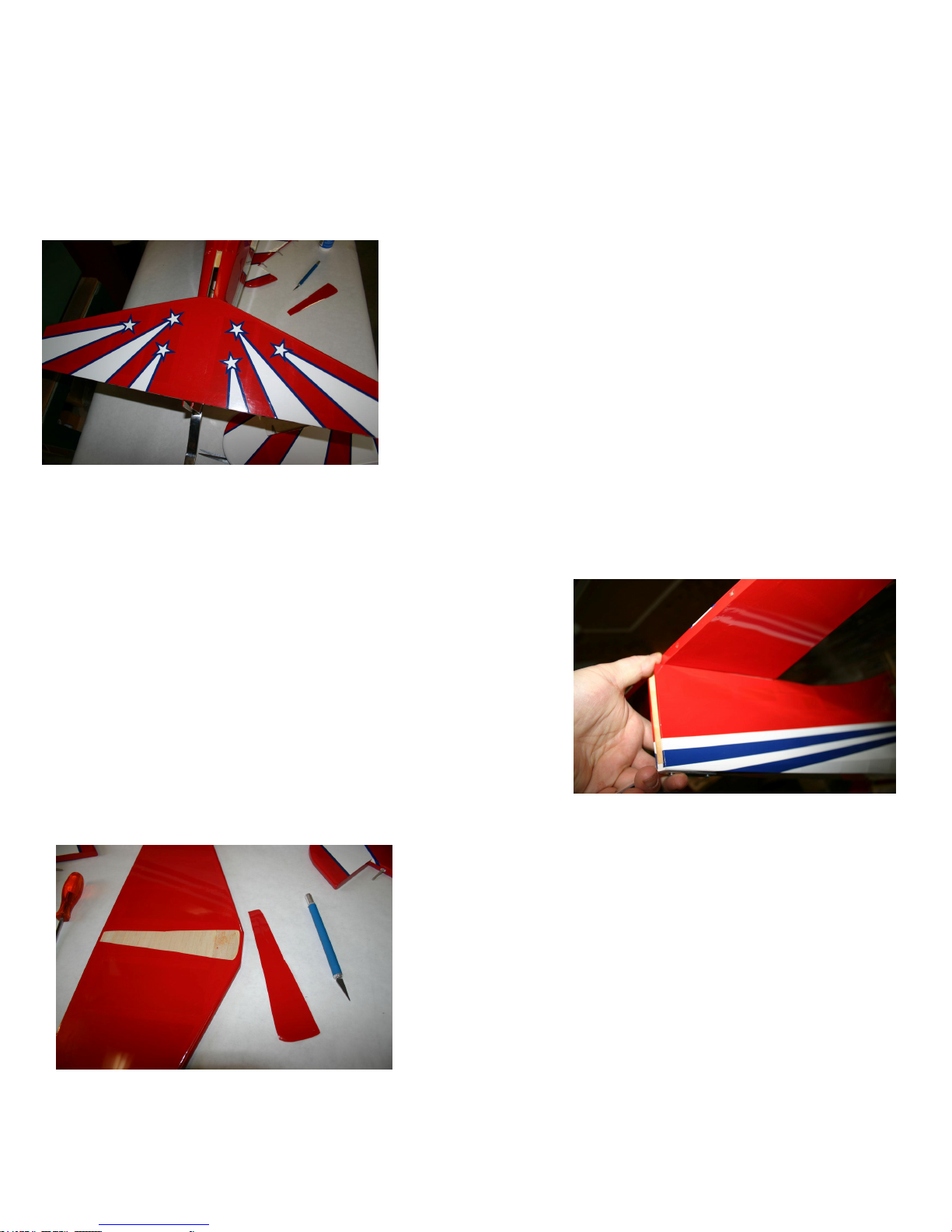
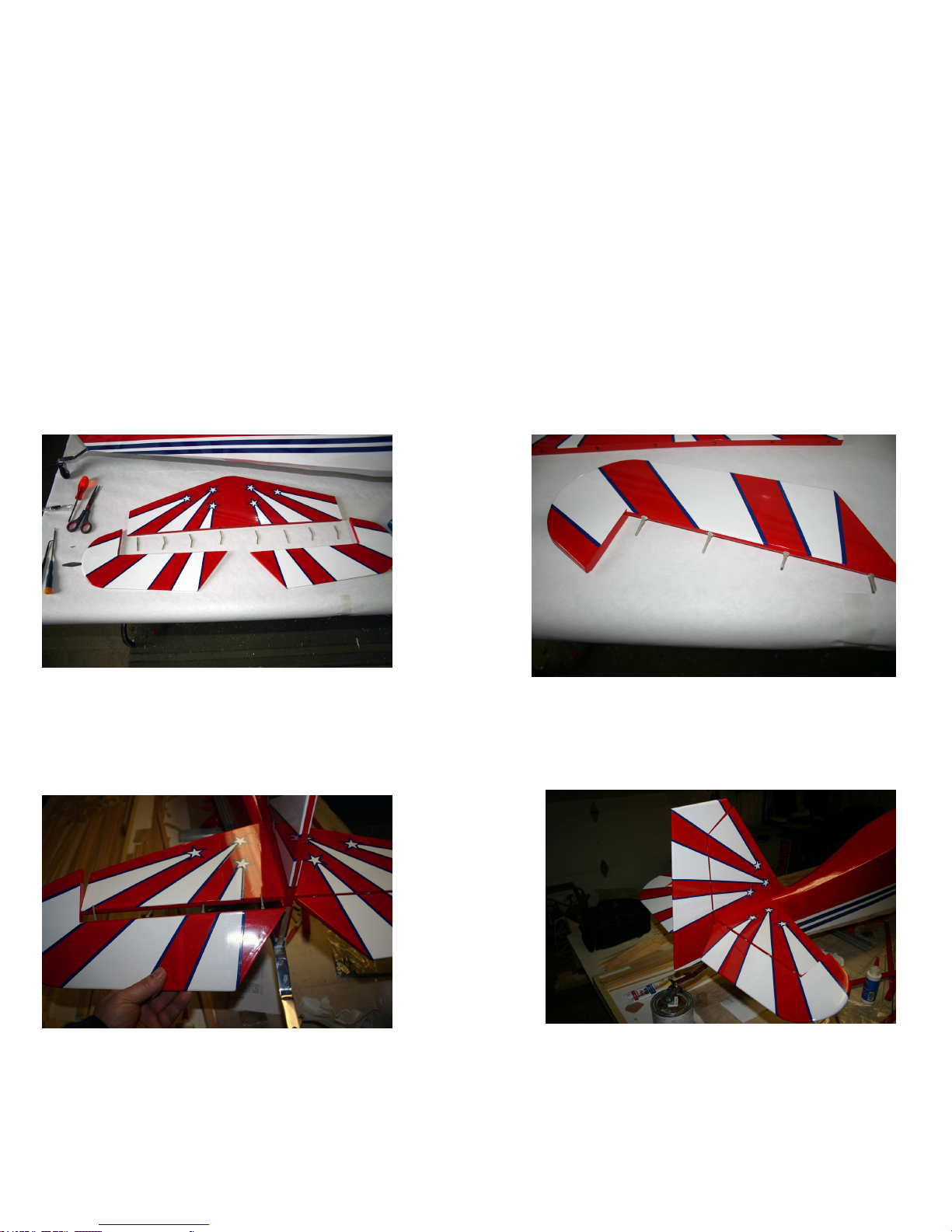
UsingasharpXactoknife,removethecoveringfromtheServoand
pullpullRuddercablecutoutsinbothsidesoftheFuselage.
Cutthesuppliedpullpullcableinto2equallengths.Youwillnotice
theyareverylongwhichwillmakeitmucheasiertothreadthroughthe
Fuselagelater.
NOTE:Savethescrappiecesifyouwanttoinstalloptionalflying
wiresfromthestabtoverticalfinonbothsides.
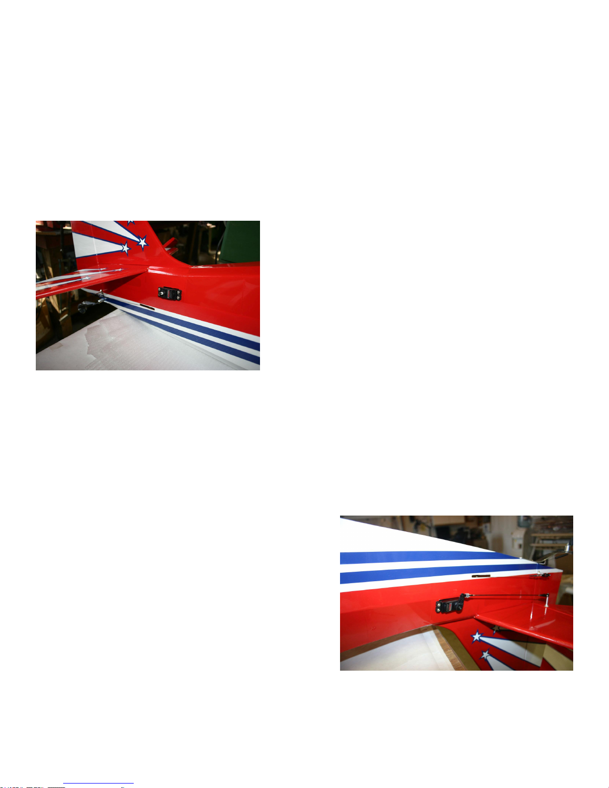
ThreadtheCablethroughthesenewuncoveredholesintherearoftheFuselage.ThreadoneCrimpFittingovertheendof
oneCable,thenthreadtheCablethroughtheouterholeintheyourLargeRudderServoArm.FoldbacktheCable1inch
andslidetheCrimpFittingovertheCableend.Whensatisfiedwiththefit,crimpthefitting.Repeatfortheotherendof
theServoArmwiththeotherCable.
TIP:Usea3/4inchpieceof1/8inchshrinktubingtocoverthesharpendoftheCablestickingoutofthecrimped
jointatbothendsoftheCable.YouwillhavetoslidethisonCableinadvance.
6

InstalltheRudderServoinsidetheFuselageusingthesupplied
hardwarewithyourradiointhecenterpositionoftheServorailinside
theFuselage.
TheRudderhas2trumpetbasesthatscrewtogetherthroughtheRudder.
PositionontrumpetbaseattheedgeoftheRudderbevelededge¾”from
thebottomoftheRudder.Markthespotanddrill3/32”dia.hole
throughtheRudder.Installthetrumpetswiththesupplieshardware. Do
notovertightenthescrews.
NOTE:StrengthentheholesbyapplyingafewdropsofthinCAglue
inbothholestoreducetheamountofbalsacompression.
ThreadthepullpullcablethroughthecutoutsinthesidesoftheFuselageanduptotheRudderServoalreadyinstalled.
Threadalltheparts,crimpfittingandclevisesasyoudidto theotherend.TemporarilyattachtheclevisestotheRudder
ServosandcarefullypullthecablethroughtheclevisesuntiltheyarepullingontheRudder.Pullthemuntiltheyareboth
equal.Whensatisfiedwiththelengths,carefullycrimpthecablefittings.
NOTE:Youcanadjustthelengthslaterwiththethreadsontheclevises.
Make2smallloopsintheendsoftheTailWheelSteeringSprings
andsecurethemtotheendsoftheRudderControlHornsandthe
TailWheelAssembly.Adjustingthetensionwillhelpcenterthe
TailWheelwiththeRudder.
7

ElevatorControls
Collecttheseparts.
ÿ 2 elevatorServosandmountinghardware(minimum70oztorque)
ÿ 2 36inchelevatorextensionleads
ÿ 2 threadedelevatorcontrol rods
ÿ 2 Servoclevises
ÿ 2 controlhorntrumpetbases
ÿ 2 trumpetclevises.(blackplastic)
ÿ 2 trumpetwashers
ÿ 2 trumpetscrews
WewillshowthestandardsetupofinstallingElevatorServoson
bothsidesoftheFuselageusing thehardwaresuppliedfromyour
radio.YoucanalsomountServo(s)ontheServoTrayatthefrontof
theFuselage.YoucanalsousejustoneElevatorServowiththe
optionalElevatorJoiner.
Youwillneedtoconnect2x18inchServoleadsifyouare
connectingthe2Servostodifferentreceiverchannels.
PossitionthetrumpetbaseattheedgeoftheElevatorbevelededge11/4”fromtheRudder.Markthespotanddrilla
3/32”dia.holethroughtheElevator.Installthetrumpetsusingthesuppliedhardware.Donotovertightenthescrews.
NOTE:StrengthentheholesbyapplyingafewdropsofCAglueineachholetoreducetheamountofbalsa
compression.
InstalltheElevatorconnectingrodstotheServoArmsand
trumpets.
NOTE:MakesuretheServoArmsexitonoppositesidesto
ensuretheElevatorswilltravelinthesamedirection.Ifyouare
connectingthesamereceiverchannelyouwillneedaYServo
extensionandone18inchextension.
8

MainWheelAxelInstallation
Collecttheseparts.
ÿ 2mainlandinggearlegs
ÿ 2mainwheelaxels
ÿ 2axelnuts
ÿ 4axellockcollars
NOTE:Youmaywanttoremoveanyburrsfromtheaxelusingarotarytoolsothatthewheelcollarswilleasilyslide
overtheaxelshaft.
SecuretheaxeltothemainLandingGearlegsusingthesuppliedhardware.DonotovertightentheAxelNutoritcould
pullapart.
HINT:Grindflatspotsontheendoftheaxleswheretheoutsidelockcollarwillmountsothesetscrewcanhold
stronger.
9

WheelPantInstallation
Collecttheseparts.
ÿ 2wheelpants
ÿ 4–632Tnuts
ÿ 4 632x½socketheadbolts
ÿ 4 flatwashers
ÿ 4lockingwashers
UsingaDremel,ensuretheholesinthewheelpantsfittheaxelnuts.
LineupthewheelpantwiththegraphicsontheFuselagesothattheyareparallelandeven.
MarkorscribethroughtheholesintheLandingGearlegsontothewheelpants.
Drill2x1/8dia.holeson thesemarks.
InstalltheTnutsfrominsidethewheelpants.
NOTE:ItisrecommendedtoapplyEpoxyinsidethewheelpant
behindtheplywoodinsertforextrastrength.
10

Usingthesuppliedhardware,2x632boltsandwashers,secure the
wheelpantstothegearlegs.Makesuretheseareverytight.
NOTE:Beverycarefulthatyoudonotcrossthreadanyofthe
boltsasthismayloosentheTnuts.
Installawheelcollarontheaxel,thenthewheelpantwiththewheel
inside,addthesecondwheelcollar.Thisisabittrickyastheyall
mustbeproperlypositionedtogetherontheaxel.
Centerthewheelinthepantsandtightenthelockcollars.Makesure
thewheelturnsfreely.
NOTE:Youmayneedtoenlargetheholeinthebottomofthewheelpantforthewheelstoturnfreely.
11

MainLandingGearInstallation
Collecttheseparts.
ÿ 1 mainlandinggearlegs
ÿ 6 832x1/2socketheadbolts
ÿ 6 lockwashers
ÿ 6 flatwashers
UsingasharpXActoknife,carefullyremovethecoveringfromtheFuselagewheretheLandingGearlegswillbe
insertedthroughtheFuselagesides.
InsertthegearlegsintotheFuselageandsecureusing3x832boltsandwashers.
TightentheboltsintothetreadedholesintheLandingGear.
NOTES:Beverycarefulthatyoudonotcrossthreadanyofthebolts.
YoumayhavetoenlargetheholesinthePlywoodMountingPlatetoallowLandingGearBoltstolineup
withthreadedholesinLandingGear.
12

SideDoorInstallation
Collecttheseparts.
ÿ 2hingepoint
ÿ 1sidedoor.
UsingEpoxyGlue,securethehingepointsintothedoorframe.
Checkforproperdirectionofthehingemovement.Letthegluedry
beforeinsertingthehingesintotheFuselage.
TrialfitthedoorintotheFuselage.Youmayneedtotrimthedoorforthe
bestfit.Whensatisfiedwiththefitandoperation,securethehingesinto
theFuselageusingEpoxyGlue.Letthehingesdrybeforeopeningthe
door.
AileronHingeInstallation
Collecttheseparts.
ÿ 8hingepoint
ÿ 2ailerons
TheAileronhingesprovidedareatopqualityhingepoint.Theyhavebeenfactorydrilledandfittedbutarenotgluedin
place.Youwillneedtoremovethempriortogluing.
DabasmallamountofEpoxyorcanopygluetoeachhingeandinsertthemintotheAileronholeuntilthehingeisjust
touchingagainsttheAileron.Remembertomakesuretheyaremovingintheproperdirection.
HINT:useasmalldropoflightoilonthehingesothatthegluedoesnotsecureorclogthehinges.
WaituntiltheglueisdrybeforegluingtheAileronsintotheWings.
13

AileronServoInstallation
Collecttheseparts.
ÿ 2 aileronServosandmountinghardware(minimum70oztorque)
ÿ 2 18inchServoExtensions
ÿ 2 aileronServohatches
ÿ 8 smallwoodscrews
ÿ 2 controlhorntrumpetbases
ÿ 2 trumpetscrews
ÿ 2 trumpetclevises(blackplastic)
UsingasharpXactoknife,removethecoveringaroundtheServo
Wingcutouts.
InstalltheServosontothefactorypreinstalledmounting
blocksusingthehardwaresuppliedwithyourradio.
NOTE:AddagussetofEpoxyaroundthebaseofeach Servo
mountingblockforextrastrength.
Connectan18inchServoExtensiontotheServosandsecurethe
connectionwithtape.
Usingalightstring,tieanutorsmallweightooneendanddropit
throughtheWingribsopeningsuntilitappearsintheAileronServo
opening.TapeortiethestringtotheServoleadandcarefullypullit
throughtheWing.
14

SecuretheServoandhatchassemblytotheWingusingthesupplied
hardware,4xwoodscrews.
AligntheAileroncontrolrodswiththeServocontrolhornsandmarkthe
locationofthecontroltrumpetssothatthebaseisattheedgeofthe
Aileronbevelededge.
Drilla3/32”dia.holeonthesemarksthroughtheAileron.
NOTE:StrengthentheholebyapplyingafewdropsofthinCAgluetoreducetheamountofbalsacompression.
SecurethetrumpetassemblytotheAileron.Donotovertighten
thescrews.
ConnectthecontrolrodstotheServosusingtheclevisesorZ
bends.
15

WingStrutAssembly
Collecttheseparts.
ÿ 2 mainwings
ÿ 1 wingtube
ÿ 2 ¼ 20nylonwingbolts
ÿ 2frontwingstruts(hasslots)
ÿ 2rearwingstruts
ÿ 2factorybentwireinterplanewingstruts
ÿ 2lowerwingcuffs
ÿ 2upperwingcuffs
ÿ 2lowerwingstrut/Fuselagemountingbrackets
ÿ 4632x½socketheadcapbolts
ÿ 8632x¾socketheadcapbolts
ÿ 8–interplanewingstrutaluminumbrackets
SlidetheAluminumWingTubeintothefactoryinstalledtubeinthe
Fuselage.Makesureanequalamountoftubeisshowingonbothsides
oftheFuselage.
CarefullyslideandpositiontheWingsontheFuselageandsecure
themtotheFuselage tightly usingthesupplied¼20nylonWing
bolts.Youwillnoticeawoodendowelisprovidedtoalignthe
WingintheproperpositionontheFuselage.
NOTE:WhentighteningtheWingBoltsdonotcrushyourServoExtensionsbetweentheWingsandFuselage.
16

UsingasharpXactoknife,removethecoveringfromtheFuselage
wherethelowerWingStrutwillbelocated.
InstalltheWingStrutBracketintotheFuselageusingthesupplied6
32x¾”bolts.YouwillnoticethattheTnutshavebeenfactory
installed.
NOTE:Beverycarefulthatyoudonotcrossthreadanyofthebolts
asthismayloosentheTnuts.
InsertthebottomoftherearStrutintotheslotinthefrontStrutand
bolttogetherusinga632x½”boltandlocknut.Youmayhaveto
grindtheleadingedgeoftherearStruttofitproperly.
SlidethelowerfrontWingStrutcuffovertheWingStrut.
NOTE:YoumayhavetotrimtheCuffswithaRazorSawor
Dremelforthebestfit.
Usingthesuppliedhardware,(632x½”bolt&locknut),securethe
WingStruttotheWingStrutbracket.Donottightenasyet.
SlidetheforwardtopWingStrutCuffovertheStrutnotingits
directionandshape.
NOTE:InstalltheStrutswiththeairfoilshapefacingtheproper
direction
17

SecuretheWingStrutassemblytotheWingusingthesuppliedhardware,632x¾”bolts.
TIPS:YoucouldinsertnylonwashersbetweentheStrutsandWingsurfacetoreducethepressureonthecoveringand
balsa.
UseamagnettohelpfindhiddenfastenersifyouarehavingdifficultyusingtheWireStrutsasaguide..
ToaddsomestrengthtotheendoftheStrutsyoucouldEpoxywoodenplugsintotheopening.
SlidethetopWingStrutCuffovertheBoltandsecureitusingclearpackingtapeorequal.
NOTE:Youcanuseclearsiliconifyouwishamorepermanentattachment.
LocateandinstalltheinterplaneWingStrutsBracketsoverthewireends.
SecuretheinterplaneStrutstotheWingusingthesuppliedhardware,632x½”boltsandnuts.Somebendingmaybe
required.
18
Other manuals for Super Decathlon ARF
1
Table of contents
Other RC Guys Toy manuals