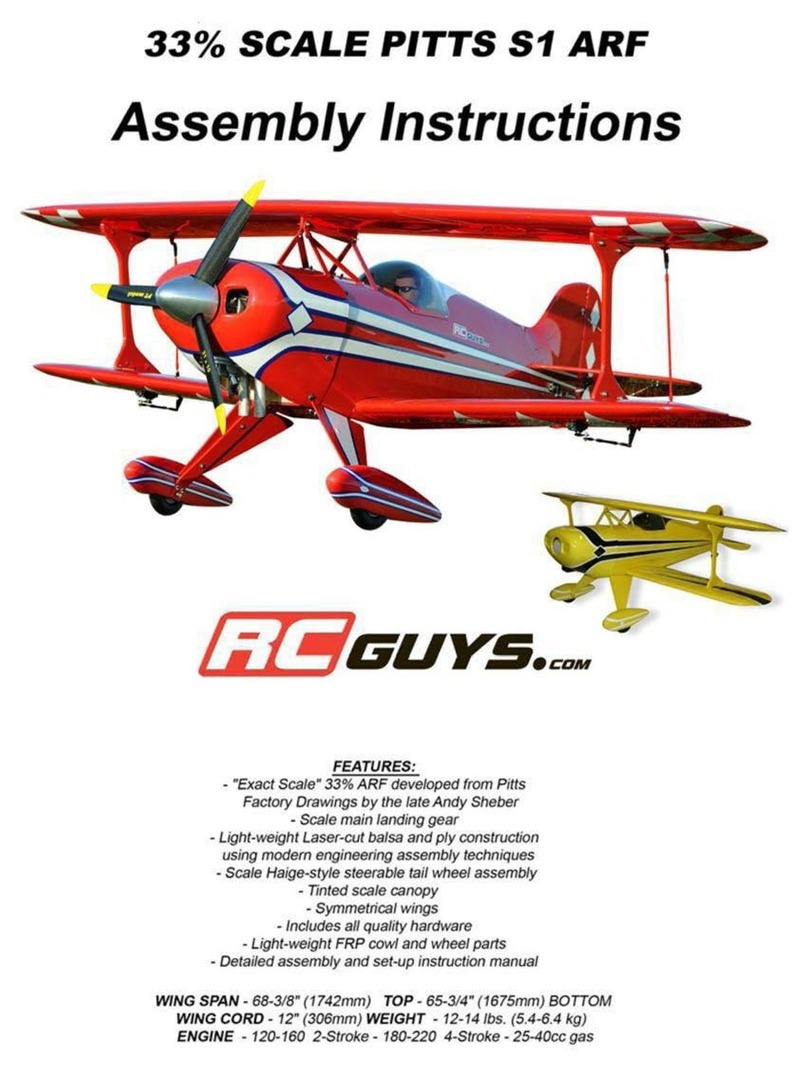
RC Guys Super Decathlon ARF User manual


TableofContents
TailWheelAssemblyInstallation ….. page01
StabilizerInstallation ….. page02
FinInstallation ….. page03
ElevatorandRudderHingeInstallation ….. page04
RudderControls ….. page05
ElevatorControls ….. page07
MainWheelAxelInstallation ….. page08
WheelPantInstallation ….. page09
MainLandingGearInstallation ….. page11
Top/SideWindowInstallation ….. page12
FrontWindshieldInstallation ….. page13
SideDoorInstallation ….. page14
AileronHingeInstallation ….. page14
Aileron Servo Installation ….. page15
WingStrutAssembly ….. page17
EngineInstallation ….. page20
FuelTankInstallation ….. page21
CowlInstallation ….. page22
RadioSetUp ….. page24
ControlSurfaceThrow ….. page24

TailWheelAssemblyInstallation
Collecttheseparts.
ÿ 1factoryassembledtailwheelbracket
ÿ 2 woodscrews
ÿ 2 tailwheelcontrolsprings
ÿ 1 tailwheelrudderbracket
ÿ 2 smallwoodscrews
Collectthepreassembledtailwheelbracketandhardware.
Positionthetailwheelassemblyoverthefuseandmarkthroughthe
holes.
Securethetailwheelassemblytothefuseusingthesuppliedhardware,
(2x woodscrews).
Securethetailwheelsteeringbrackettotherudderusingthesupplied
hardware,(2xwoodscrews).
Make2smallloopsintheendsofthetailwheelsteeringspringsand
securethemtothebracketandsteeringarms.
1

StabilizerInstallation
Collecttheseparts.
ÿ 1stabilizer
ÿ 1fin
Positionthestabilizeroverthefuseandcenteritusingaruler.
Usingascribeorpen,carefullymarkalongthesidesofthefuse.
RemovethecoveringjustinsidethesemarksusingasharpXactoknife.
Repositionthestabilizeroverthefuseandwhensatisfiedwiththefit,
glueitinplaceusingepoxy.
2

Fin Installation
Positionthefinoverthefuseandscribeamarkalongthestabilizersides.
Removethecoveringonthestabilizerjustinsidethesemarks.
Repositionthefinonthestabilizerandwhensatisfiedwiththefit,
glueinplaceusingepoxy.Useasquaretoholdthefin90degreesto
thestabilizeruntiltheepoxydries.Youmaywanttotapeitinplace.
Note:Wipeawayanyexcessepoxyusingdenaturedalcohol.
3

Elevator/RudderHingeInstallation
Positionandglueinplaceusingepoxyorcanopyglueallhingepointsintothefactorypredrilledholes.Donotgluethem
intothestabilizerorfinatthistime.
Note:Checkthatthehingesareoperatingintheproperdirectionbeforethegluedries.Youmaywanttoplaceasmall
dropoflightoilonthehingessothegluewillnotsticktothem.
4

RudderControls
Collecttheseparts.
ÿ 1 rudderservoandmountinghardware
ÿ 1 rudderwirecable
ÿ 4 cablecrimpfittings
ÿ 4 cableclevises
ÿ 4 cableclevisnuts
ÿ 2 control horntrumpetbases
ÿ 1 trumpetscrew
ÿ 2trumpetclevises.(blackplastic)
UsingasharpXactoknife,removethecoveringfromtheservoand
pullpullruddercablecutoutsinbothsidesofthefuse.
Cutthesuppliedpullpullcableinto2equallengths.Youwillnotice
theyareverylongwhichwillmakeitmucheasiertothreadthroughthe
fuselater.
Note:Savethescrappiecesifyouwanttoinstall optional flyingwires
fromthestabtoverticalfin onbothsides.
Assemblethepullpullcablesandclevises.Threadonecablecrimp
fittingoverthecable.Threadthecablethroughtheclevisandthen
thoughthecrimpfitting.Whensatisfiedwiththefit,crimpthefitting.
Note:Youmayalsowanttoaddapieceofshrinktubingtocover
overthecrimpedjoint.
Installtherudderservoinsidethefuseusingthesuppliedhardware
withyourradiointhecenterposition oftheservorailinsidethefuse.
Therudderhas2trumpetbasesthatscrewtogetherthroughtherudder.
Positionontrumpetbaseattheedgeoftherudderbevelededge¾”
fromthebottomoftherudder.Markthespotanddrill3/32”dia.hole
throughtherudder.Installthetrumpetswiththesupplieshardware.
Donotovertightenthescrews.
Note:StrengthentheholesbyapplyingafewdropsofthinCAglue
inbothholestoreducetheamountofbalsacompression.
Installtherearrudderclevisesontothetrumpets.
5

Threadthepullpullcablethroughthecutoutsinthesidesofthefuseanduptotherudderservoalreadyinstalled.
Threadalltheparts,crimpfittingandclevisesasyoudidtotheotherend.Temporarilyattachtheclevisestotherudder
servosandcarefullypullthecablethroughtheclevisesuntiltheyarepullingontherudder.Pullthemuntiltheyareboth
equal.Whensatisfiedwiththelengths,carefullycrimpthecablefittings.
Note:Youcanadjustthelengthslaterwiththethreadsontheclevises.
6

ElevatorControls
Collecttheseparts.
ÿ 2 elevatorservosandmountinghardware
ÿ 2 18inchelevatorextensionleads
ÿ 2 threadedelevatorcontrolrods
ÿ 2 servoclevises
ÿ 2 control horntrumpetbases
ÿ 2 trumpetclevises.(blackplastic)
ÿ 2 trumpetwashers
ÿ 2 trumpetscrews
Usingthehardwaresuppliedfromyourradio,installtheelevator
servosonbothsidesofthefuse.
Youwillneedtoconnect2x18inchservoleadsifyouare
connecting the2servostodifferentreceiverchannels.
Possitionthetrumpetbaseattheedgeoftheelevatorbevelededge11/4”fromtherudder. Mark the spotanddrilla3/32”
dia.holethroughtheelevator.Installthetrumpetsusingthesuppliedhardware.Donotovertightenthescrews.
Note:StrengthentheholesbyapplyingafewdropsofCAglueineachholetoreducetheamountofbalsa
compression.
Installtheelevatorconnectingrodstotheservoarmsandtrumpets.
Note:Makesuretheservoarms exiton oppositesidestoensure
theelevatorswilltravelinthesamedirection.Ifyouare
connectingthesamereceiverchannelyouwillneedaYservo
extensionandone18inchextension.
7

MainWheelAxelInstallation
Collecttheseparts.
ÿ 2mainlandinggearlegs
ÿ 2mainwheelaxels
ÿ 2axelnuts
ÿ 4axellockcollars
Securetheaxeltothemainlandinggearlegsusingthesuppliedhardware.
Note:Youmaywanttoremoveanyburrsfromtheaxelusingarotarytoolsothatthewheelcollarswilleasilyslide
overtheaxelshaft.
8

WheelPantInstallation
Collecttheseparts.
ÿ 2wheelpants
ÿ 4–632Tnuts
ÿ 4 632x ½sockethead bolts
ÿ 4 flatwashers
ÿ 4lockingwashers
UsingaDremel,ensuretheholesinthewheelpantsfittheaxelnuts.
Installawheelcollaron theaxel,thenthewheelpantwiththewheel
inside,thenaddthesecondwheelcollar.Thisisabittrickyasthey
allmustbeproperlypositionedtogetherontheaxel.Donottighten
thecollarsasyet.
Note:Youmayneedtoenlargetheholeinthebottomofthewheelpantforthewheelstoturnfreely.
9

Line upthewheelpantwiththegraphicsonthefusesothattheyareparallelandeven.
Markorscribethroughtheholesinthelandinggearlegsontothewheelpants.
Drill2x1/8dia.holesonthesemarks.
InstalltheTnutsfrominsidethewheelpants.
Usingthesuppliedhardware,2x632boltsandwashers,securethewheel
pantstothegearlegs.Makesuretheseareverytight.
Note:Beverycarefulthatyoudonotcrossthreadanyoftheboltsasthis
mayloosentheTnuts.
Centerthe wheelinthepantsandtightenthelockcollars.Makesure
thewheelturnsfreely.
10

MainLandingGearInstallation
Collecttheseparts.
ÿ 1 mainlandinggearlegs
ÿ 6 832x1/2sockethead bolts
ÿ 6 lockwashers
ÿ 6 flatwashers
UsingasharpXActoknife,carefullyremovethecoveringfromthefusewherethelandinggearlegswillbeinserted
throughthefusesides.
Insertthegearlegsintothefuseandsecuretothemountsusing3x832boltsandwashers.Youwillnotethe Tnutshave
beenfactoryinstalled.
Tightenthebolts.
Note:BeverycarefulthatyoudonotcrossthreadanyoftheboltsasthismayloosentheTnuts.
11

Top/SideWindowInstallation
Collectthese parts.
ÿ 1topwindow
ÿ 2 frontsidewindows
ÿ 2 rearsidewindows
UsingasharpXactoknife,carefullyremovethecoveringfromthetopwindowopeningonthefuse.
Usingcanopygluecarefullyaddasmallbeadofglueto theedgesof
thewindow.
Becarefulnottogetanyglueonyourfingersorthewindows.
Placethewindowsintotheircutoutsinthefuseandtapeinplaceuntil
theglueisdry.
Note:Youmaywanttoaddweightstoholdthetopwindowinplace
andmaskingtapeonthesidewindowsuntilthegluedries.
12

FrontWindshieldInstallation
Collecttheseparts.
ÿ 1 frontwindshield
ÿ 6 smallwoodscrews
Positionthefrontwindshieldoverthefusemakingsureitisevenandslightlyoverthetopedgeofthefuse.Itshouldalso
fitwellalongsidethefrontedgesoftheleadingedgeofthewingsandflatonthefrontofthefuse.
Usingamarker,carefullymarkwherethescrewswillgo,3oneachside.Removethewindshieldanddrillasmallhole
overthesemarks.Repositionthewindshieldandsecureittothefuseusingthesupplied 6woodscrews.Donotover
tightenthescrews.
Note:Youmayalsousecanopygluetosecurethewindshield.Tapetoholdinplaceuntilthegluedries.
13

SideDoorInstallation
Collecttheseparts.
ÿ 2hingepoint
ÿ 1sidedoor.
Usingepoxyglue,securethehingepointsintothedoorframe.
Checkforproperdirectionofthehingemovement.Letthegluedry
beforeinsertingthehingesintothefuse.
Trialfitthedoorintothefuse.Youmayneedtotrimthedoorforthebest
fit.Whensatisfiedwiththefitandoperation,securethehingesintothe
fuseusingepoxyglue.Letthehingesdrybeforeopeningthedoor.
AileronHingeInstallation
Collecttheseparts.
ÿ 8hingepoint
ÿ 2ailerons
Theaileronhingesprovidedareatopqualityhingepoint.Theyhavebeenfactorydrilledandfittedbutarenotgluedin
place.Youwillneedtoremovethempriortogluing.
Dabasmallamountofepoxyorcanopygluetoeachhingeandinsertthemintotheaileronholeuntilthehingeisjust
touchingagainsttheaileron.Remembertomakesuretheyaremovingintheproperdirection.
Hint:useasmalldropoflightoilonthehingesothatthegluedoesnotsecureorclogthehinges.
Waituntiltheglueisdrybeforegluingtheaileronsintothewings.
14

AileronServoInstallation
Collecttheseparts.
ÿ 2 aileronservosandmountinghardware
ÿ 2 18inchservoextensions
ÿ 2 aileronservohatches
ÿ 8 smallwoodscrews
ÿ 2 controlhorntrumpetbases
ÿ 2 trumpetscrews
ÿ 2 trumpetclevises(blackplastic)
UsingasharpXactoknife,removethecoveringaroundtheservo
wingcutouts.
Installtheservosontothefactorypreinstalledmounting
blocksusingthehardwaresuppliedwithyourradio.
Connectan 18inchservoextensiontotheservosandsecure the
connection with tape.
Using alightstring,tieanutorsmallweightooneendanddropit
throughthewingribsopeningsuntilitappearsintheaileronservo
opening.Tapeortiethestringtotheservoleadandcarefullypullit
throughthewing.
15

Securetheservoand hatchassemblytothewingusingthesupplied
hardware,4xwoodscrews.
Aligntheaileroncontrolrodswiththeservocontrolhornsandmark the
locationofthecontroltrumpetssothatthebaseisattheedgeofthe
aileronbevelededge.
Drilla3/32”dia.holeonthesemarksthroughtheaileron.
Note:StrengthentheholebyapplyingafewdropsofthinCAgluetoreducetheamountofbalsacompression.
Securethetrumpetassemblytotheaileron.Donotovertightenthe
screws.
ConnectthecontrolrodstotheservosusingtheclevisesorZ
bends.
16

WingStrutAssembly
Collecttheseparts.
ÿ 2 mainwings
ÿ 1 wingtube
ÿ 2 ¼ 20nylonwingbolts
ÿ 2frontwingstruts(longerthanrearwing struts)
ÿ 2rearwingstruts
ÿ 2factorybentinterplanewingstruts
ÿ 2lowerwingcuffs
ÿ 2upperwingcuffs
ÿ 2lowerwingstrut/fusemountingbrackets
ÿ 4632x ½socketheadcapbolts
ÿ 8632x ¾socketheadcapbolts
ÿ 8–interplanewingstrutbrackets
Slidethealuminumwingtubeintothefactoryinstalledtubeinthe
fuse.Makesureanequalamountoftubeisshowingonbothsidesof
thefuse.
Carefullyslideandpositionthewingsonthefuseand securethem
tothefuseusingthesupplied¼20nylon wingbolts.Youwill
noticeawoodendowelisprovidedtoalignthewingintheproper
position on thefuse.
Note:Donotcrush yourservoextensionsbetweenthewingsandfuse.
17

UsingasharpXactoknife,removethecoveringfromthefuse wherethe
lowerwingstrutwillbelocated.
Installthewingstrutbracketintothefuseusingthesupplied632x ¾”
bolts.YouwillnoticethattheTnutshavebeenfactoryinstalled.
Note:Beverycarefulthatyoudonotcrossthreadanyoftheboltsasthis
mayloosentheTnuts.
Insertthebottomoftherearstrutintotheslotinthefrontstrutandbolt
togetherusinga632x½”boltandlocknut.
Slidethelowerfrontwingstrutcuffoverthewingstrut.
Note:Youmayhavetotrim thecuffswitharazorsaworDremelfor
thebestfit.
Usingthesuppliedhardware,(632x ½” bolt),securethewingstrut
tothewingstrutbracket.Donottightenasyet.
Slidetheforward topwingstrutcuffoverthestrutnotingitsdirection
andshape.
Note:Installthestrutswiththeairfoilshapefacingtheproper
direction
Slidetherearwingstrutintotheslotinthefrontwingstrutandsecureitusingthesuppliedhardware, 632x ½”boltand
nut.
18
Other manuals for Super Decathlon ARF
1
Table of contents
Other RC Guys Toy manuals
Popular Toy manuals by other brands

Basic XL
Basic XL BXL-BF10 manual

esky
esky HUNTER operating instructions

Flis Kits
Flis Kits Thing-a-ma-Jig Assembly instructions

Step 2
Step 2 Love to Entertain Kitchen manual

Lightmybricks
Lightmybricks LEGO BIRDS OF PARADISE 10289 installation guide

Step 2
Step 2 Patches the Rocking Horse 8866 quick start guide