RCA LED24A45RQ User manual

Part No,: RN03236G0300
Model Number°
Please register your product at www, rca,com
Please keep your sales receipt and keep the record of
the serial number and the date of purchase in order to
receive warranty parts and service.
The serial number is located at the back of the TV.
SerialNumber/NzimerodeseriedeTV
DateofPurchase/Fechadelacompra
_!_ Ii !_i!"
Changing Entertainment, Again, _,_,_
wvwv.rca.com _ _ '_,:_

iMuchas gracias por su uso del presente productoT Cuando usted disfruta de su nuevo producto,
por favor tenga en cuenta los consejos de seguridad:
POSBLES PROBLEMEAS
= La experiencia de entretenimiento de cine en casa es una tendencia
creciente y los grandes monitores de pantatla plana son muy populares.
Sin embargo, los monitores de pantalla plana no se han instalado siempre
en los soportes adecuados o instalado de acuerdo con las recomendaciones
de fabricante.
Los monitores de pantatla plana que se han instalado inadecuadamente
en tocadores, estantedas, estantes, escritorios, oradores, baL_tes o carros
se pueden caer y causar el daSo corporal.
iAL FABRICANTE LE IMPORTA!
• La industda electr6nica del consumidor est_ comprometida a hacer el
entretenimiento de casa agradable y seguro.
AJUSTAR HASTA SEGURIDAD
• Un tamaSo fijo NO es adecuado para todos. Siga las recomendaciones de
fabricante para la instataci6n segura y et uso de su monitor de pantalla plana.
• Lea con cuidado y entienda todas las instrucciones adjuntas para el uso
propio de este producto.
• No permita a los niSos a subir al equipo o jugar con muebles y televisiones.
• No cloque los monitores de pantalla plana en el muebte que se puede usar
f&cilmente como escal6n, asi como una c6moda.
• Recuerde que los niSos pueden tlegar a ser excitados al ver una programaci6n,
especialmente en el monitor de pantatla plana "m_s grande que vida".EI cuidado
se tiene que empezar por poner o instalar et monitor donde no se
puede empujar, detener al costado del camino ni echar abajo.
• El cuidado se tiene que empezar por encaminar todos los cordones y cables
conectados al monitor de pantalla plana para que no se puedan tirar o agarrar
por los ni_os curiosos.
MONTAJE DE PARED: S! USTED DECIDE AMONTAR SU
MONITOR DE PANTALLA PLANAA LA PARED, SIEMPRE:
" Use una montura que se ha recomendado por el fabricante de monitor
y/o listado por un laboratorio independiente (como UL, CSA, ETL).
• Siga todas las instrucciones ofrecidas por el fabricante de monitor
y montaje de pared.
o Si usted tiene cualquier duda sobre su habilidad para instalar seguramente
su monitor de pantalla ptana, contacte a su distribuidor para la instalaci6n
profesional.
• Compruebe que la pared adonde se est_ montando et monitor es adecuada.
Algunos montajes de la pared no son disedados para ser montados a paredes
con tachones de acero o la vieja construcci6n de bloque de ceniza. Si usted
esta inseguro, contacte a un instalador profesional.
• Por Io menos dos personas se requieren para la instataci6n. Los monitores
de pantalla plana puede ser pesados.

CAUTION
Caution: To reduce the risk of electric shock, do not remove cover or back. No user-serviceable parts inside.
Refer servicing to qualified service personnel.
WARNING: TO REDUCE THE RISK OF FIRE OR ELECTRIC SHOCK, DO NOT EXPOSE THIS APPLIANCE TO RAIN
OR MOISTURE.
CAUTION: CHANGES OR MODIFICATIONS NOT EXPRESSLY APPROVED BY THE PARTY RESPONSIBLE FOR
COMPLIANCE WITH THE FCC RULES COULD AVOID THE USERS AUTHORITY TO OPERATE THIS
EQUIPMENT.
FCC Information
This equipment has been tested and found to comply with the limits for a Class B digital device, pursuant to Part 15 of the
FCC rules. These limits are designed to provide reasonable protection against harmful interference in a residential installation.
This equipment generates, uses and can radiate radio frequency energy and, if not installed and used in accordance with
the instructions, may cause harmful interference to radio Communications. However, there is no Guarantee that interference
will not occur in a particular installation. If this equipment does cause harmful interference to radio or television reception,
which can be determined by turning the equipment off and on, the user is encouraged to try to correct the interference by
one or more of the following measures:
- Reorient or relocate the receiving antenna.
- Increase the separation between the equipment and the receiver.
- Connect the equipment into an outlet on a circuit different from that to which the receiver is connected.
- Consult the dealer or an experienced radio/TV technician for help.

1. Readtheseinstructions.
2. Keeptheseinstructions.
3. Heedallwarnings.
4. Followallinstructions.
5. Donotusethisapparatusnearwater.Forexample,donotusenearalaundrytub,inawetbasement,ornearaswimming
pool,andthelike.
6. Cleanonlywithdrycloth.
7. Donotblockanyventilationopenings.Installinaccordancewiththemanufacturer'sinstructions.Slotsandopeningsin
thecabinetbackorbottomareprovidedforventilation,toensurereliableoperationoftheTVandtoprotectitfrom
overheating.Theseopeningsmustnotbeblockedorcovered.TheopeningsshouldneverbeblockedbyplacingtheTV
onabed,sofa,rug,orothersimilarsurface.
8. Donotinstallnearanyheatsourcessuchasradiators,heatregisters,stoves,orotherapparatus(includingamplifiers)that
produceheat.
9. Donotdefeatthesafetypurposeofthepolarizedorgrounding-typeplug.Apolarizedplughastwobladeswithonwider
thantheother.Agrounding-typeplughastwobladesandathirdgroundingprong.Thewidebladeorthethirdprongis
providedforyoursafety.Iftheprovidedplugdoesnotfitintoyouroutlet,consultanelectricianforreplacementofthe
obsoleteoutlet.
10.Protectthepowercordfrombeingwalkedonorpinchedparticularlyatplugs,conveniencereceptacles,andthepoint
wheretheyexitfromtheapparatus.
11.Onlyuseattachments/accessoriesspecifiedbythemanufacturer.
12.Useonlywithcart,stand,tripod,bracket,ortablespecifiedbythemanufacturer,orsoldwiththe
apparatus.Whenacartisused,usecautionwhenmovingthecart/apparatuscombinationto
avoidinjuryfromtip-over.ATVandcartcombinationshouldbemovedwithcare.Quickstops,
excessiveforce,andunevensurfacesmaycausetheTVandcartcombinationtooverturn.
13.Unplugthisapparatusduringlightningstormsorwhenunusedforlongperiodsoftime.ForaddedprotectionforthisTV
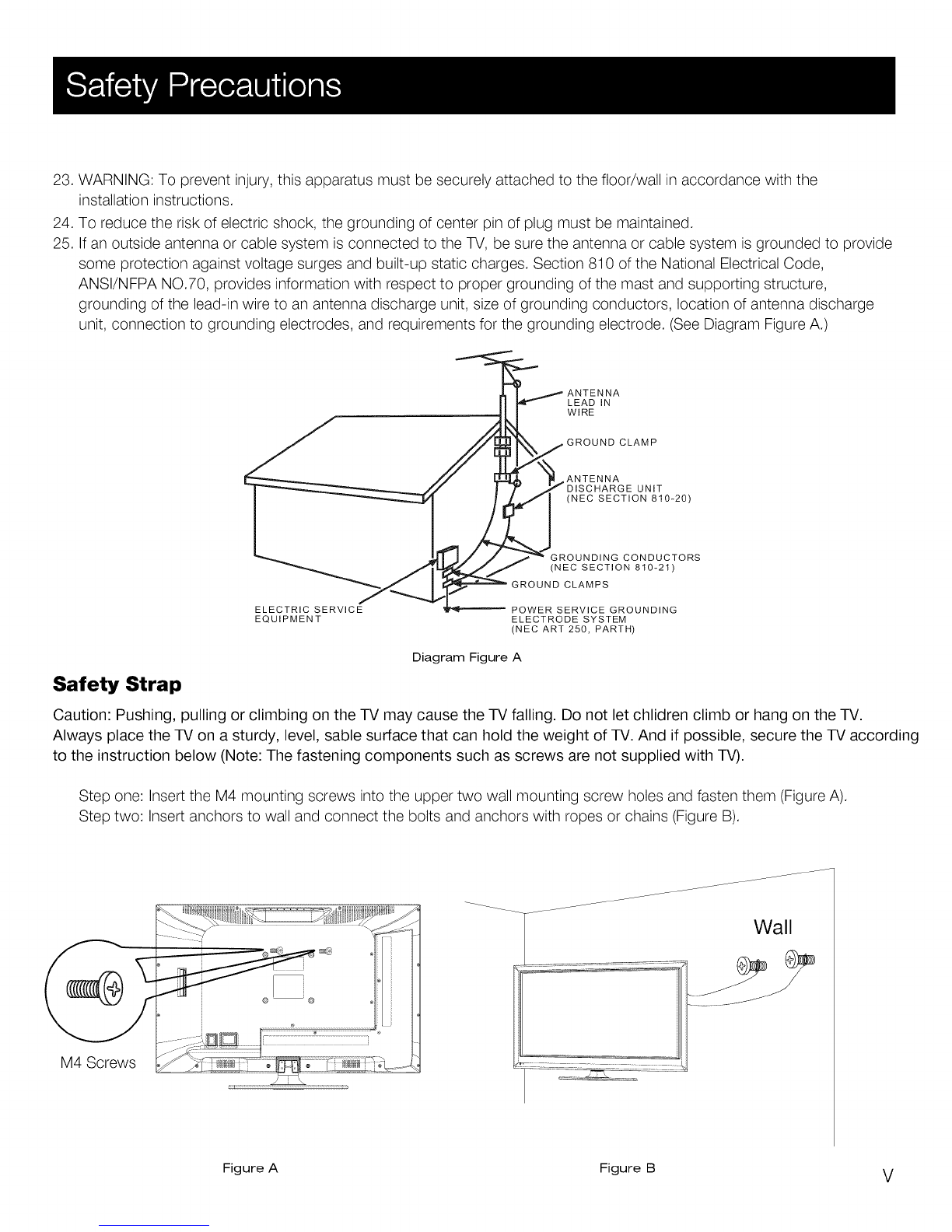
receiverduringalightningstorm,orwhenitisleftunusedforlongperiodsoftime,unplugitfromthewalloutletand
disconnectantennaorcablesystem.ThiswillpreventdamagetotheTVduetolightningandpowerlinesurges.
14.Referallservicingtoqualifiedservicepersonnel.Servicingisrequiredwhentheapparatushasbeendamagedinanyway,
suchaspower-supplycordorplugisdamaged,liquidhasbeenspilledorobjectshavefallenintotheapparatus,the
appratushasbeenexposedtorainormoisture,doesnotoperatenormally,orhasbeendropped.
15.ThisTVshouldbeoperatedonlyfromthetypeofpowersupplyindicatedontheratinglabel.Ifcustomerisnotsurethe
typeofpowersupplyinyourhome,consultyourappliancedealerorlocalpowercompany.ForTVremotecontrolbattery
power,refertotheoperatinginstructions.
16.TheTVsetshallnotbeexposedtodrippingorsplashing.Noobjectsfilledwithliquids,suchasvases,shallbeplacedon
theTVset.
17.NeverpushobjectsofanykindintothisTVthroughopeningsastheymaytouchdangerousvoltageorotherelectrical
partsthatcouldresultinfireorelectricshock.NeverspillliquidofanykindintotheTV.
18.UnplugtheTVfromthewalloutletbeforecleaning.Donotuseliquidoraerocleaners.Useadampclothforcleaning.
19.ThisTVshouldneverbeplacednearoroveraradiatororheatresource.ThisTVshouldnotbeplacedinabuilt-in
installationsuchasabookcaseorrackunlessproperventilationisprovidedorthemanufacturer'sinstructionshavebeen
adheredto.
20.DonotplacethisTVonanunstablecart,stand,tripod,bracket,ortable.TheTVmayfall,causingseriousinjuryto
someone,andseriousdamagetotheappliance.
21.DonotattempttoservicethisTVbyyourselfbecauseopeningorremovingcoversmayexposeyoutodangeroushigh
voltageorotherhazards.Referallservicingtoqualifiedservicepersonnel.
22.ThisdevicecomplieswithPart15oftheFCCRules.Operationissubjecttothefollowingtwoconditions:(1)thisdevice
maynotcauseharmfulinterference,and(2)thisdevicemustacceptanyinterferencereceived,includinginterference
thatmaycauseundesiredoperation.
IV

23. WARNING: To prevent injury, this apparatus must be securely attached to the floor/wall in accordance with the
installation instructions.
24. To reduce the risk of electric shock, the grounding of center pin of plug must be maintained.
25. If an outside antenna or cable system is connected to the TV, be sure the antenna or cable system is grounded to provide
some protection against voltage surges and built-up static charges. Section 810 of the National Electrical Code,
ANSI/NFPA NO.70, provides information with respect to proper grounding of the mast and supporting structure,
grounding of the lead-in wire to an antenna discharge unit, size of grounding conductors, location of antenna discharge
unit, connection to grounding electrodes, and requirements for the grounding electrode. (See Diagram Figure A.)
LEAD IN
WIRE
CLAMP
ANTENNA UNIT
(NEC SECTION 810_20)
GROUNDING CONDUCTORS
(NEC SECTION 810_21)
GROUND CLAMPS
ELECTRIC SERVICE
EQUIPMENT POWER SERVICE GROUNDING
ELECTRODE SYSTEM
(NEC ART 250, PARTH)
Diagram Figure A
Safety Strap
Caution: Pushing, pulling or climbing on the TV may cause the TV falling. Do not let chlidren climb or hang on the TV.
Always place the TV on a sturdy, level, sable surface that can hold the weight of TV. And if possible, secure the TV according
to the instruction below (Note: The fastening components such as screws are not supplied with TV).
Step one: Insert the M4 mounting screws into the upper two wall mounting screw holes and fasten them (Figure A).
Step two: Insert anchors to wall and connect the bolts and anchors with ropes or chains (Figure B).
Wall
M4 Screws
Figure A Figure B V

Child Safety Guide .................................................................................................................................... I, II
Caution and Warning .................................................................................................................................... III
FCC Notice ...................................................................................................................................................... III
Safety Precautions .................................................................................................................................. IV, V
Preparation for Your New TV ...................................................................................................................... 8
Check Accessories ...................................................................................................................................... 8
Setup TV Table Stand .................................................................................................................................. 8
Select TV Location ...................................................................................................................................... 8
Connection and Using .................................................................................................................................. 8
TV Stand Installation .................................................................................................................................... 9
TV Signal Connection ................................................................................................................................. .I0
Cable Connections ...................................................................................................................................... 11
Side Panel Connections ............................................................................................................................ .12
Connecting AV Composite Video device (Good Video Quality) ....................................................................... 12
Connecting YPbPr Component device (Better Video Quality) ......................................................................... 13
Connecting HDMI device (Best Video Quality) .............................................................................................. 14
Connecting a Computer .............................................................................................................................. .!5
How to Obtain Various Kinds of input Sources .............................................................................................. .I5
TV Jacks Explanation .................................................................................................................................. !6
Top Panel and Front Panel ........................................................................................................................ .17
Top Panel Buttons ...................................................................................................................................... !7
Front Panel ................................................................................................................................................. 17
Remote Control Instructions ..................................................................................................................... 18
Inserting Batteries in the Remote ................................................................................................................ .18
Remote Control Reception Angle ................................................................................................................ .I8
Learning about Remote Control .............................................................................................................. .19
Remote Control Buttons ............................................................................................................................. :19
Initial Setup .................................................................................................................................................... 20
Menu Language .......................................................................................................................................... 20
Signal Type ................................................................................................................................................. 20
Auto Channel Search ................................................................................................................................... 20
Basic Operations .......................................................................................................................................... 21
Turning On and Off ...................................................................................................................................... 21
Choosing TV Channel .................................................................................................................................. 21
Selecting input Source ................................................................................................................................. 21
Adjusting TV Stand Angle ............................................................................................................................. 2!
Channel Bar ................................................................................................................................................ 22
Adjusting Volume ........................................................................................................................................ 22
EPG (Electronic Program Guide) .................................................................................................................. 22
6

OSD Menu Operations ............................................................................................................................. 23
Adjust the OSD Screen ............................................................................................................................. 23
Picture Menu ............................................................................................................................................ 23
Sound Menu ............................................................................................................................................ 25
Channel Menu .......................................................................................................................................... 26
Parental Menu .......................................................................................................................................... 27
Setup Menu .............................................................................................................................................. 31
Others Menu ............................................................................................................................................ 33
Frequently Asked Questions (FAQs) ..................................................................................................... 34
Troubleshooting ......................................................................................................................................... 35
V-Chip Rating Explanations .................................................................................................................... 37
US V-Chip Rating System .......................................................................................................................... 37
Canadian English Rating System ................................................................................................................ 37
Canadian French Rating System ................................................................................................................ 38
Wall Mounting Unit Specification ............................................................................................................ 39
Product Specification ................................................................................................................................ 40
Warranty Card ............................................................................................................................................ 41
Warranty Card (Spanish) ............................................................................................................................ 43
7

Before Turning On TV
Check Accessories
Check the accessories that are packed with your TV.
I:t :1_ [Oili :l[_Ze] _i i :{e] I/|vA[.,,.-,]tit.*!_Ip][_,,,,[o.]:t :_vAv_r.,v.,v.,1:_.,ti iq--.ti:__]
PART NO.: RE20QP83
MACHINE
SCREWS
M4 x 12mm, 4pcs
Part# RS01TM41 2H
RCA .....
USER'S
GUIDE
RCA
QU ICK START
GUIDE
I IlVJ[-',]lf;!_Im]
REMOTE CONTROL
GUIDE
Setup TV Table Stand
Please refer to TV Stand Installation guide in next page to carry out stand installing.
Select TV Location
Select a flat, stable table to locate your TV set. Pleasefollow the Safety Instructions when locating the TV.
Connection and Using
After placing your TV properly, you can connect the TV with power supply and cable components. For further information, see page
12 to page 15.
8 Note: Above accessories are subject to change without notice.

TV LED24A45RQ is packaged with the TV stand separated from the cabinet. To setup the TV table stand, please carry out the
installation according to the instructions below.
Step One
Place the TV faced down on a soft cloth or cushion to prevent the LED LCD
panel from being damaged.
The LED LCD panel is easy to scratch, so please:
1. Choose an absolutely flat surface to place the TV on.
2. Use soft cloth or cushion to face the TV panel.
Do not put TV on table directly.
Note: Always unplug the AC cord first when installing or
removing the stand.
Step Two
Take the stand. Pleasealign the screw holes of the stand and TV.
Align the four holes in TV stand body to the screwholes
in TV stand base.
Step Three
Insertthe four M4 machine screws (which are totally the same) and tighten them.
Pedestal Screws Quantity Part #
M4 x 12mm 4pcs RS01TM412H
19

The first step in connecting your TV is obtaining the signal. Your TV has a side panel, which allows you to receive analog and/or
digital television channels via TV jack.
Before connecting your TV, determine using an antenna or a cable service to obtain the signal.
A. Antenna
Connect the antenna to TV via coxial cable on TV jack of the side panel. You are ready to receive air local digital and analog
channels.
B. Cable TV service
Connect the cable TV wall jack to TV via coaxial cable on TV jack of the side panel. You are ready to receive off-air local digital
and analog channels.
C. Set-Top Box
If you use a set-top box, you may need to call your cable company or satellite service provider, which use a special connection,
please refer to the user's guide of set-top box.
Note: Do not plug the AC cord until you have accomplished all the connections.
Cable TV Antenna
AC 110V/60Hz Or
AC Power Cord
(Connect after all the other connections are done.)
10

Choose Your Connections
Your TV supports various of connecting ways from other devices (such as DVD, VCR, Set-top box, ect.). Please follow the
table sheet to choose the cables which adapt to your device.
AV IN VIDEO, L-AUDIO-R
COMPONENT Y/Pb/Pr
L-AUDIO-R
Video/Audio cable
Go to page 12
Audio Cable
Go to page 13
HDMI 1/DVl, 2
COMPONENT video cable
HDMI-DVl cable
HDMI TMcable
PC INPUT VGA, SOUND/DVl
Audio cable with 3.5mm terminal
VGA cable
Go to page 14
Go to page 15
Note:
HDMI, the HDMI logo, and High-Definition Multimedia Interface are trademarks or registered trademarks of HDMI Licensing LLC
Caution:
Unplug the AC cord when you connect other devices to TV.
11

Connecting AV Composite device (Good Video Quality)
To connect an composite AV device, such as a DVD player, follow these steps:
1. Connect the VIDEO jack on the back of TV to the video output jacks of device via video cable (yellow).
2. Connect the L-AUDIO-R jacks on the back of TV to the audio output jacks of device via audio cable.
Notice the left channel jack and plugs are white and the right channel jack and plugs are red.
Note. AV signal belongs to composite video. This kind of video signal has regular good display quality.
Composite Video Connection
The picture below is an example of a connection using the composite video jack.
The back of TV
The output panel of other device
12

Connecting YPbPr Component device (Better Video Quality)
To connect a component device, such as a DVD player, follow these steps:
1. Connect the COMPONENT IN Y/Pb/Pr jack on the side of TV to the video output jacks of device via video cable (green,
blue and red).
2. Connect the L-AUDIO-R jacks on the side of TV to the audio output jacks of device via audio cable.
Notice the left channel jack and plugs are white and the right channel jack and plugs are red.
Note. Y/Pb/Prjacks are component video. This kind of video signal has better display quality.
Component Video Connection
The picture below is an example of a connection using the component video jack.
The back of TV
The output panel of other device
13

Connecting HDMI device (Best Video Quality)
To connect an HDMI device, such as a DVD player, please connect the HDMI 1/DVl, 2 jack on the back of TV to the output
jack of device via HDMI cable.
To connect an DVl device, such as a computer via DVl port of PC and HDMI jack of TV:
1. Connect the HDMI 1/DVl, 2 jack on the back of TV to the DVl port of PC via HDMI-DVl cable.
2. Connect the SOUND/DVl jack on the back of TV to the audio output jack of computer with audio cable (3.5mm stereo jack).
To connect an DVl device, other AV device via DVl port of device and HDMI jack of TV:
1. Connect the HDMI 1/DVl, 2 jack on the back of TV to the DVl port of device via HDMI-DVl cable.
2. Connect the SOUND/DVl jack on the back of TV to the audio output jack of device with audio cable (dual-channel RCA
jacks to 3.Smm stereo jack).
Note: !. HDMI (High-Definition Multimedia Intet_ace) is acompact audio/video interface for transmitting uncompressed digital
data. It carries the audio and video signal via the same cable and has the best display quafity.
2. HDMI-DVI cable transfers only video signal from DVI port of DVI device to HDMI jack of TV. For audio signal, please
connect audio output to SOUND/DVI jack on TV back panel
HDMI Connection
The picture below is an example of a connection using the HDMI video jack.
The bacl, -iV
The output panel of HDMI device
14
PC The output panel of other AV device

Connecting a computer
To connect a computer, follow these steps:
1. Connect the VGA port on the back of TV to the VGA output jack of device via D-sub 15-pin cable.
2. Connect the SOUND/DVl jack on the back of TV to the audio output jack of computer with audio cable (3.5mm).
Note: Ifyou want to use your TV as a monitor, please notice that the maximum resolution for LED24A45RQ is !920"!080.
Please set the computer graphic correctly.
PC Connection
The picture below is an example of a connection using your TV as a PC monitor.
The back of TV
PC
How to Obtain Various Kinds of Input Sources
After connection is done, press INPUT button on remote control or TV top panel to choose the input source you need.
See page 21, Basic Operation of TV.
15

ANT/CABLE: Connect to receive the signal from your antenna or cable via coaxial cable.
AV IN (VIDEO, L-AUDIO-R ): Connect an AV device that has composite video jacks, such as a VCR
or a DVD player. To access device connected to these jacks, press the INPUT button on your
remote; then press the up/down arrow to select AV. Press the ENTER button at last to confirm.
•AUDIO L: Left audio channel connection. The left audio connector is usually white. For mono audio
sources, be sure to use the left AUDIO INPUT.
•AUDIO R: Right audio channel connection. The right audio connector is usually red.
Note:• The AV input (Video fn), Component input (Y, Pb, Pr) share the same audio input jacks L-Audio-R.
COMPONENT IN Y/Pb/Pr: Connect a device that has component video jacks, such as a DVD player.
To access device connected to the Y/Pb/Pr jack, press the INPUT button on your remote; then press the up/down arrow to
select Component. Press the ENTER button at last to confirm.
•Y/Pb/Pr (Component Video): They provide good picture quality because the video signal is separated into three components.
Use three video-grade or component video cables for the connection. When using Y/Pb/Pr, make sure you connect left and
right audio cables to the Audio L and Audio R jacks.
HEAD PHONE: Connect a 3.5mm headphone for personal audio.
DIGITAL AUDIO OUT: Connect a coaxial cable for digital audio output.
PC INPUT ( VGA, SOUND/DVI ):
SOUND/DVl : Use to obtain sound when a PC or DVl device is connected to the VGA!HDMI input. Use 3.5mm stereo
mini-pin cable to connect PC or DVl divece to TV.
VGA: Connect your computer or other device with a VGA output to this jack using a 15-pin, D-sub cable.
HDMI IN ( 1/DVl, 2 ): (High-Definition Multimedia Interface) It provides an uncompressed digital connection that carries both
video and audio data by way of an integrated mini-plug cable. To connect HDMI/DVl device, see page 14.
SERVICE: For service use only. Do not connect any device.
16

Back Panel Buttons
Ifyou cannot locate your remote, you can use the back panel buttons on your TV to operate many TVfeatures.
,/ _ + VOL - • CH • MENU INPUT _'
INPUT: Displays the Source Select List.
MENU : Displays the TV Main Menu.
CH • : Scans down through the channel list. In the TV menu system, it acts like the down arrow on the remote control
and can be used to select menu options.
CH • : Scans up through the channel list. Inthe TV menu system, it acts likethe up arrow on the remote control
and can be used to select menu options.
VOL-: Decreases the volume. Inthe TV menu system, it acts likethe left arrow on the remote control and can be used to
select menu options.
VOL+: Increases the volume. Inthe TV menu system, it acts like the right arrow on the remote control and can be used to
select menu options.
POWER (_b): Turns the TV on and off.
Front Panel
About remote control working distance and angle, see page 18.
Power/Standby Indicator: Light up in red when the TV is in standby mode. Light out when the TV is on.
Remote Control Sensor: Remote control IR sensor, which receives infrared ray sent by remote control.
Power/Standby Indicator
i Remote Control Sensor
17

Inserting Batteries in the Remote
• Remove the cover of battery cabin on the back of the remote control by pushing the tab and sliding the cover.
• Insert two AAA batteries, making sure the polarities (+ and -) are aligned correctly.
• Place the cover back.
If the remote control does not work, check these points:
• Are the polarities (+, -) correct?
• Are the batteries worn out?
• Is there an AC power failure?
• Is the power cord plugged in?
• Is there any interference or block near the remote
control sensor?
CAUTION:
• Used batteries should be recycled.
• Keep out of children's reach.
• DO NOT use new and old batteries together.
• Change both the batteries at the same time.
• When not using the remote control for a long time,
remove the batteries from the unit.
Remote Control Reception Angle
Use your remote control within the distance and angle range shown below.
7 meters
r___[,
Universal Remote Control Code List
For Universal Remote Control brands listed below, please
use accompanying codes and refer to your Universal
Remote Control User Manual for basic Instruction for
changing TV code to operate the TV model.
• Codes for DIRECTV: 0178, 10178
• Codes for Time Warner Cable: 0178, 10178
• Codes for Cox Communications: 0178
• Codes for Comcast: 10178
• Codes for Dish Network: 627
• Codes for Fios Verizon: 0205, 0057, 0493, 0775
18

Remote Control Buttons
POWER (_): Turns the TV on or off.
MUTE (ur_): Reduces the TV volume to its minimum level. Press again to restore the volume.
Numeric Buttons: Use these buttons to enter numbers.
"--": To enter a digital channel with a sub-channel, enter the main channel; then, press this
button to enter the sub-channel and press ENTER.
Arrows (_1/I_/A /• ): Uses the four arrows to highlight different items in the TV menu or
change the value. The up/down arrow can also work as CH"/CH'_
button, and the left/fight arrow can also work as VOL-/VOL+ button.
Recall (_._): Returns to the previous channel.
EPG: Shows Electronic Program Guide (see page 22).
INPUT: Accesses the available input channels (TV, AV, Component, HDMI, PC).
Use the arrows to highlight options, and press ENTER to select.
ENTER: Enter and confirm button.
MENU: Accesses the Main Menu, or return to the upper level of a sub-menu.
EXIT: Exits the current menu or function.
VOL+ or VOL-: Increases or decreases the TV volume.
CH^ or CHv: Scans up or down through the current channel list. Press once to change
the channel up or down; press and hold to continue changing channels.
PICTURE: Switches between the preset picture mode (see page 23).
SOUND: Switches between the preset sound mode (see page 25).
ASPECT: Switches between the preset screen size mode (see page 24).
DISPLAY: Displays the Channel Bar (see page 22).
CC: Selects the closed caption.
MTS: Selects the multi-channel television sound.
SLEEP: Selects the sleep timer, after which the TV will shut off automatically.
FAV.: Adds the current channel to your favorite list, or erases the current channel from
your favorite list (ifthis channel is a favorite channel already).
FAV.+ or FAV.- : Scans up or down through the current favorite channel list.
PAUSE/FREEZE : Freeze the current screen frame, press again to return to normal.
NOTE : The keys not fisted are for DVD control they are not avai/abie for this TV modeL
Remote control part number RE20QP83
19

If it is the first time you turn on your TV, or you have done Clear Channel List option (see page 30), the initial setup menu appears
automatically.
Menu Language
To choose your menu language, press the left/fight arrow until the language you need appears.
Available languages: English, French and Spanish.
Signal Type
To choose your TV tuner signal type, press the lefVright arrow until Air or Cable appears.
Note: please select TV signal type according to the antenna or cable closed circuit TV you use.
Auto Channel Search
To execute auto channel search, press the up/down arrow to highlight Auto Channel Search and press ENTER button.
What to notice:
1. The channel search access starts from the Analog TV channel searching and ends at Digital TV channel searching.
2. The channels that have been found will be stored automatically.
3. You can press MENU or EXIT button to skip analog/digital channel searching.
4. You can press MENU or EXIT repeatedly to end the channel searching.
20
Other manuals for LED24A45RQ
2
Table of contents
Other RCA LED TV manuals