RCA RC940 User manual

Wireless Portable Phone Jack
Conector para Teléfono Portátil Inalámbrico
VOIP/MODEM
VOIP/MÓDEM
PHONE
TELÉFONO
SATELLITE
SATÉLITE
User’s Guide RC940
Guía del Usuario

2
This symbol is intended to alert you to the presence of uninsulated dangerous
voltage within the system’s enclosure that might be of sufficient magnitude to
constitute a risk of electric shock. Do not open the system’s case.
This symbol is intended to inform you that important operating and maintenance
instructions are included in the literature accompanying the system.
Read and follow precautions when installing and using the Wireless Phone Jack System.
• Readandunderstandallinstructions.
• Followallwarningsandinstructionsmarkedonthesystemandinthisguide.
• Unplugthissystemfromthewalloutletbeforecleaning.Donotuseliquidoraerosol
cleaners.Useadampclothforcleaning.
• Donotusethissystemnearwater;forexample,nearabathtub,washbowl,kitchensink,or
laundrytub,inawetbasement,orinornearaswimmingpool.
• Thissystemshouldneverbeplacednearoroveraheatradiatororregister.Thissystem
should not be placed in a built-in installation unless proper ventilation is provided.
• Thissystemshouldonlybeoperatedfromthetypeofpowersourceindicatedinthisguide
and on the system’s label. If you are not sure of the type of power supplied to your home or
building,consultyourlocalpowercompany.
• Neverspillliquidofanykindonthesystem.
• Toreducetheriskofelectricshock,donotdisassemblethissystem,buttakeittoaqualified
servicefacilitywhenserviceorrepairisrequired.
• Openingorremovingthecoversmightexposeyoutodangerousvoltagesorotherrisks.
Incorrectreassemblycancauseelectricshockwhenthesystemissubsequentlyused.
• Unplugthesystemfromthewalloutletandreferservicingtoaqualifiedservicefacility
under the following conditions:
A. When the AC plug is damaged.
B. Ifliquidhasbeenspilledintothesystem.
C. Ifthesystemhasbeenexposedtorainorwater.
D. If the system does not operate normally by following the operating instructions.
E. If the system has been dropped or the cabinet has been damaged.
F. Ifthesystemexhibitsadistinctchangeinperformance.
• Avoidusingatelephone,otherthanacordlessphone,duringanelectricalstorm.Thereisa
remote risk of electric shock from lightning.
• Donotusethetelephonetoreportagasleakintheareaoftheleak.
FCC Information
We designed your Wireless Phone Jack System to conform to federal regulations and you can
connectittomostphonelines.However,eachdeviceyouconnectdirectlytothephonelinedraws
powerfromit.Thispowerdrawisthedevice’sringerequivalencenumber,orREN.TheRENis
shown on the base unit’s label.
Ifyouconnectmorethanonephoneorotherdevicedirectlytothephoneline,addupallthe
RENs.Ifthetotalismorethanfive(orthreeinruralareas),yourphonesmaynotring.Ifringer
operationisimpaired,removeadevicefromtheline.YourWirelessPhoneJackutilizesRJ-11
phone connectors.
Note: YourWirelessPhoneJackSystemhasaRENof0.1B,andsodoesnotaffectyourphone’s
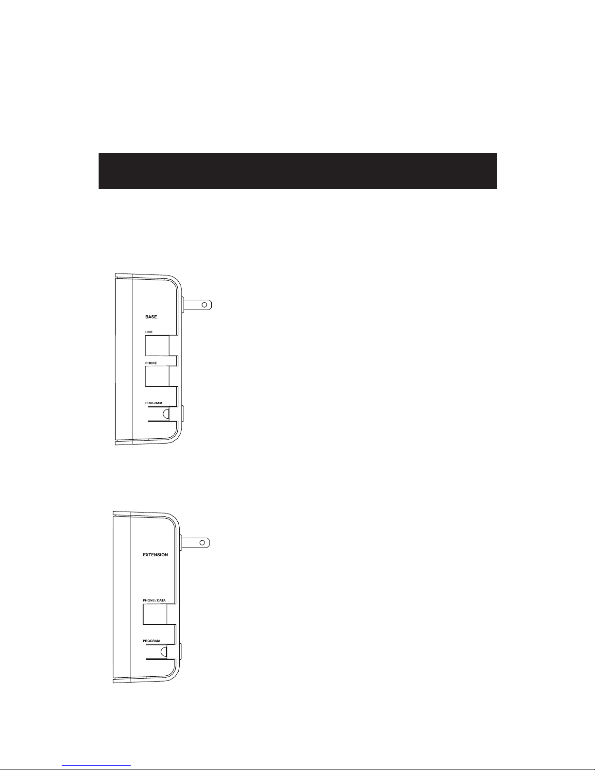
abilitytoring.Also,thephoneyouplugintotheextensionunitdoesnotplaceanyloadonthe
telephoneline.However,thephoneyouplugintothebaseunitdoesaffectthetotalREN.Ifyour
WirelessPhoneJackSystemcausesproblemsonthephoneline,thetelephonecompanycan
disconnect your service. The phone company tries to notify you in advance. If advance notice is
notpractical,thetelephonecompanynotifiesyouassoonaspossibleandadvisesyouofyour
righttofileacomplaintwiththeFCC.
Caution:Changesormodificationsnotexpresslyapprovedbythepartyresponsiblefor
compliancecouldvoidtheuser'sauthoritytooperatetheequipment.
CAUTION
RISK OF ELECTRIC SHOCK
DO NOT OPEN
CAUTION: TO REDUCE THE RISK OF ELECTRIC SHOCK DO NOT REMOVE COVER OR BACK
NO USER SERVICEABLE PARTS INSIDE REFER SERVICING TO QUALIFIED SERVICE PERSONNEL.
CAUTION
RISK OF ELECTRIC SHOCK
DO NOT OPEN
CAUTION: TO REDUCE THE RISK OF ELECTRIC SHOCK
DO NOT REMOVE COVER OR BACK ,NO USER
SERVICEABLE PARTS INSIDE REFER SERVICING TO
QUALIFIED SERVICE PERSONNEL.
DO NOT EXPOSE TO WATER OR MOISTURE.
CAUTION
RISK OF ELECTRIC SHOCK
DO NOT OPEN
CAUTION: TO REDUCE THE RISK OF ELECTRIC SHOCK DO NOT REMOVE COVER OR BACK
NO USER SERVICEABLE PARTS INSIDE REFER SERVICING TO QUALIFIED SERVICE PERSONNEL.
CAUTION
RISK OF ELECTRIC SHOCK
DO NOT OPEN
CAUTION: TO REDUCE THE RISK OF ELECTRIC SHOCK
DO NOT REMOVE COVER OR BACK ,NO USER
SERVICEABLE PARTS INSIDE REFER SERVICING TO
QUALIFIED SERVICE PERSONNEL.
DO NOT EXPOSE TO WATER OR MOISTURE.
Important Safety Precautions

3
English
FCC Part 68 & Class B Notices
YourWirelessPhoneSystemcomplieswithPart68ofFCCRules.Youmust,uponrequest,
providetheFCCregistrationnumberandtheRENtoyourtelephonecompany.Thesenumbers
are shown on the label on the base unit.
ThisequipmentcomplieswiththelimitsforaClassBdigitaldeviceasspecifiedinPart15ofFCCRules.
These limits provide reasonable protection against radio and TV interference in a residential area.
However,yourequipmentmightcauseTVorradiointerferenceevenwhenitisoperatingproperly.To
eliminate interference you can try one or more of the following corrective measures:
• Reorientorrelocatethereceivingantenna
• IncreasethedistancebetweenthesystemandtheradioorTV
• UseoutletsondifferentelectricalcircuitsfortheequipmentandtheradioorTV
Read the Troubleshooting section of this manual for directions on remedying the problem.
Lightning
YourWirelessPhoneJackSystemhasbuilt-inprotectioncircuitstoreducetheriskofdamage
fromsurgesinthetelephoneline.TheseprotectioncircuitsmeetorexceedtheFCCrequirements.
However,lightningstrikingthetelephoneorpowerlinescandamageyoursystem.Lightning
damageisnotcommon.Nevertheless,ifyouliveinanareathathassevereelectricalstorms,we
suggest that you unplug the system during storms to reduce the possibility of damage.
Important Notes On Operation
• DonotplugPhoneJacksintopowerstripsorsurgeprotectors.
• PhoneJackExtensiondoesnotoperateduringapoweroutage.
• PhoneJackSystemcanonlybeusedforsinglephoneline.
• BesuretoplugBaseunit(twojacksonside)infirstbeforeExtensionunit(onejackonside).
• Ifyoucannotgetadialtone,unplugbothphonejacksandresetunitsfollowingthesection
titled“Troubleshooting”onpage10.
• It is very important that directions are followed in order. In the event of a problem unplug both
units,removeallcordsandstartagain.
Industry Canada Equipment Notice
TheIndustryCanadalabelidentifiescertifiedequipment.Thiscertificationmeansthatthe
equipmentmeetscertaintelecommunicationsnetworkprotective,operationalandsafety
requirementsasprescribedintheappropriateTerminalEquipmentTechnicalDocuments(s).The
Departmentdoesnotguaranteetheequipmentwilloperatetotheuser’ssatisfaction.
Beforeinstallingthisequipment,usersshouldensurethatitispermissibletobeconnectedtothe
facilitiesofthelocaltelecommunicationscompany.Theequipmentmustalsobeinstalledusingan
acceptable method of connection. The customer should be aware that compliance with the above
conditions may not prevent degradation of service in some situations.
Repairstocertifiedequipmentshouldbecoordinatedbyarepresentativedesignatedby
thesupplier.Anyrepairsoralterationsmadebytheusertothisequipment,orequipment
malfunctions,maygivethetelecommunicationscompanycausetorequesttheusertodisconnect
theequipment.
Usersshouldensurefortheirownprotectionthattheelectricalgroundconnectionsofthepower
utility,telephonelinesandinternalmetallicwaterpipesystem,ifpresent,areconnectedtogether.
This precaution may be particularly important in rural areas.
Caution:Usersshouldnotattempttomakesuchconnectionsthemselves,butshouldcontactthe
appropriateelectricinspectionauthority,orelectrician,asappropriate.
Product Registration
Please register your product online as soon as possible. Registering your product allows us to
contact you if needed.
Product Information
Keep your sales receipt to obtain warranty parts and service and for proof of purchase. Attach
it here and record the serial and model numbers in case you need them. These numbers are
located on the product.
ModelNo.: ________________________________________
Purchase Date: ____________________________________
Dealer/Address/Phone: _____________________________

4
Unpacking
Carefullyremoveunitsfrompackaging.Ifthereisanyvisibledamage,
DONOTattempttooperatetheequipment.Notifyyourdealeror
shipping carrier immediately. Keep this guide for future use.
What's In the Package?
Getting Started
• Base Unit
The base unit has two modular telephone
jacksandaPROGRAMbuttononitsright
side. Its front has an indicator light.
Thisistheunityouplugyourexisting
phone or VoIP line into.
NOTE: Install the Base Unit FIRST to ensure
proper performance.
• Extension Unit
Theextensionunithasonemodular
telephonejackandaPROGRAMbuttonon
its right side. Its front has an indicator light
as well.
This is the unit that can be moved from
locationtolocationtocreateaphone,
modem,orVoIPjackinanelectricaloutlet.
• Telephone Cord (6’)
A6ft.telephonecordisprovidedto
connectthebaseunittotheexistingwall
phonejack.

5
English
FollowthesestepstousetheRC940witharegularphone,fax/modem,
or satellite receiver.
NOTE: For installation with a VoIP service, see page 7.
Installing the Base Unit
Installation for Phone, Fax/Modem, & Satellite
1
2
3
1.Plugthebaseunitintoan
electrical outlet near an
existingwallphonejack.The
indicator light on the front of
the base turns red.
Important: The base and
extension units work best
when plugged directly into an
electrical outlet. Do not plug
them into a surge protector,
plug strip, or extension cord.
2.PlugoneendoftheprovidedtelephonecordintotheLINEjackon
therightsideofthebaseunit,andtheotherendintoanyexisting
wallphonejack.Thebaseunit'sindicatorlightshouldturngreen.
3.Ifyouwanttouseaphoneatthisjack,plugitintothePHONEjackon
the side of the base unit.
Installing and Testing the Extension Unit
1.Plugtheextensionunitintoan
electrical outlet where you want
anewphonejack.Theindicator
lightontheextensionunitblinks
red.Assoonastheextension
andbaseunitsrecognizeeach
other,theextensionunit's
indicator light turns green.
1
2
2.Tomakesureyou'vecompletedtheinstallationsuccessfully,plug
ahandsetorcordlessphoneintothePHONE/DATAjackonthe
extensionunit.
Important: If your phone requires power to operate, don't forget to
plug its power adapter in! The extension unit provides the phone
signal to the connected phone, not power.
continues on next page...

6
Note: The indicator lights on the base and extension units blink green
when the handset connected to the extension unit is taken off its hook.
3.Pickupthehandsetandlistenforadialtone.Ifyouhearone,you've
successfullysetupthebaseandextensionunits.Ifyoudonotheara
dialtone,seetheTroubleshootingsectioninthismanualforpossible
solutions.
Ifyou'reusingtheextensionunitforanadditionaltelephone,
congratulations: you've completed the installation! If you want to use
theextensionjackwithasatellitereceiver,modem,orfax,seethe
instructions that follow for your device.
Connecting to a Satellite Receiver
Afterinstallingthebaseandextensionunits,followthesestepsto
connecttheextensionunittoasatellitereceiver.
1.Disconnectthephoneyouusedtotestfordialtonefromthe
extensionunit.
2. Plug the telephone line cord from your satellite receiver into the
PHONE/DATAjackonthesideoftheextensionunit.
Iftheindicatorlightontheextensionunitstaysgreen,yoursatellite
receiverisnowconnectedtoyourphoneline.Ifitturnsred,seethe
Troubleshooting section in this manual for possible solutions.
Connecting to a Modem or Fax
Afterinstallingthebaseandextensionunits,followthesestepsto
connecttheextensionunittoamodemorfax.
1.Disconnectthephoneyouusedtotestfordialtonefromthe
extensionunit.
2.Plugthetelephonelinecordfromyourmodemorfaxintothe
PHONE/DATAjackonthesideoftheextensionunit.
Iftheindicatorlightontheextensionunitstaysgreen,yourmodem
orfaxisnowreadytooperate.Ifitturnsred,seetheTroubleshooting
section in this manual for possible solutions.
Note: Under certain circumstances where static is present in your
telephone line, the RC940 may not filter or remove such static. This
condition can affect modem or fax machine performance. Try installing
the base unit and/or the extension unit in another electrical outlet.

7
English
VOIP decoder box
1
2
3
FollowthesestepstousetheRC940withaVoIPservice.
NOTE: You must subscribe to a VoIP service with decoder box in order to
use the RC940 for an additional VoIP line. The RC940 will not work with
VoIP without a decoder box.
Installing the Base Unit
Installation for VoIP Service
1.Plugthebaseunitintoan
electrical outlet near your VoIP
decoderbox.Theindicator
light on the front of the base
turns red.
Important: The base and
extension units work best
when plugged directly into an
electrical outlet. Do not plug
them into a surge protector,
plug strip, or extension cord.
2.PlugoneendoftheprovidedtelephonecordintotheLINEjackonthe
rightsideofthebaseunit,andtheotherendintophoneoutputofthe
VoIPdecoderbox.Thebaseunit'sindicatorlightshouldturngreen.
3.PlugthephoneyouusewiththedecoderboxintothePHONEjackon
the side of the base unit.
Installing and Testing the Extension Unit
1.Plugtheextensionunitinto
an electrical outlet where
youwantanewVoIPjack.
The indicator light on the
extensionunitblinksred.As
soonastheextensionandbase
unitsrecognizeeachother,the
extensionunit'sindicatorlight
turns green.
1
2
2.Tomakesureyou'vecompletedtheinstallationsuccessfully,plug
ahandsetorcordlessphoneintothePHONE/DATAjackonthe
extensionunit.
Important: If your phone requires power to operate, don't forget to
plug its power adapter in! The extension unit provides the phone
signal to the connected phone, not power.
continues on next page...

8
Note: The indicator lights on the base and extension units blink green
when the handset connected to the extension unit is taken off its hook.
3.Pickupthehandsetandlistenforadialtone.Ifyouhearone,you've
successfullysetupthebaseandextensionunits.Ifyoudonotheara
dialtone,seetheTroubleshootingsectioninthismanualforpossible
solutions.
Programming Additional Extension Units
Followthesestepstoaddextensionunitstoyourcurrentsetup.
Note: If your first extension unit's indicator light remains red, follow
these steps to get the extension and base units to recognize each other.
1.PressthePROGRAMbuttonontheright
side of the base unit. The indicator on
the front of the base unit begins to flash
orange. The base unit is now in program
mode,whichallowsnewlyaddedextension
units to get the current link code.
NOTES:
• If the base unit's indicator light turns solid
red before it begins to flash orange, you
need to press the PROGRAM button on
all extension units while the base is in
program mode.
• Make sure neither the base nor extension
unit is plugged into a surge protector, plug
strip, or extension cord.
2.PressthePROGRAMbuttonontheright
sideoftheaddedextensionunit(or,
ifyou'renotaddinganextension,the
unitwithasolidredindicatorlight).The
indicatorlightontheextensionunitflashes
red,thenturnssolidgreen.
Ifyouareaddingmorethanoneextension
unit,pressthePROGRAMbuttononeach
addedextensionunit.

9
English
NOTES:
• If the extension unit's indicator light does not turn green in step 2,
press its PROGRAM button again.
• Do not press the PROGRAM button on the extension unit while
its indicator light is flashing. Wait until its indicator light is not
flashing.
• If the base unit is not in program mode when you press the
extension unit's PROGRAM button, the extension unit's indicator
light will flash red for about ten seconds and then turn solid red.
If you still want to program the extension unit, start from step 1
above. If you do not want to program the extension unit, unplug
the extension unit, and plug it back in to restore a solid green
indicator light.
4.Whenyouhavefinishedprogrammingalltheextensionunits,press
thePROGRAMbuttonontherightsideofthebaseunit.Thistakes
thebaseunitoutofprogrammode;thebase'sindicatorlightturns
green.
Makesuretheindicatorlightsontheextensionunitsarealsosolid
green.
NOTE: If you forget to press the button on the base unit after you've
finished programming, the base unit will remain in program mode
for five minutes and then return to normal operating mode (its
indicator light returns to solid green).

10
Troubleshooting
Most problems with the RC940 can be solved by correcting common
mistakes in installation.
Ifthestepsbelowdonotsolveyourdifficulty,removebothunitsfrom
theelectricaloutlets,removeallcordsandreinstallmakingsureto
followinstructionsonpages8-9.Ifyoustillexperiencedifficultywiththe
units,contactRCAcustomerserviceat1-800-409-5111.
Yoursituation(systemlocation,characteristicsofthehome/office)can,in
someinstances,affectperformanceandoccasionalinterferencemaybe
experienced.Somestatic,buzzingorhummingatcertainlocationswithin
theoperatingareaispossible.However,ifyouexperienceunusuallevels
ofnoise,followthetroubleshootingactionsbelow.
Problem Possible Solutions
Base and/or
extensionunit
indicator light not
illuminated
•Theunitmaynotbegettingpower.Makesuretheunit
is plugged directly into a functional A/C outlet—not
aswitchedoutlet,plugstrip,unitsurgesuppressor,
extensioncordorGFCI-protectedoutlet.Tryvarious
electricaloutlets.Ifproblempersists,contactcustomer
support at the number listed above.
•Theindicatorlightmayhavefailed.
Extensionunit’s
indicator light is
solid red
•Thebaseunitmaynotbeinstalledcorrectly.Installbase
unit.(RefertotheInstallationsection.)
•Extensionmightbetoofarfromthebaseunit.Relocate
eitherthebaseorextensionunittoanotherelectrical
outlet.Ifindicatorlightonextensionunitremainssolid
red,reprogramthelinkcodeonextensionunit(see
Programming Additional Extension Units).
Base unit’s
indicator light is
flashing orange
Baseunitisinprogrammode.Ifextensionunitsarealready
programmed,pressthePROGRAMbuttonontherightside
of the base unit. The indicator light should turn solid green.
Base unit’s
indicator light is
solid red
•Thephonecordmaynotbeconnectedproperlytothe
baseunit'sLINEjack.Checkthisconnection.
•Thebaseunit'sindicatorlightturnsredwhenthephone
connected to it has a non-cordless handset off hook. Make
sure the handset is properly hung up.
Nodialtone •Makesurethephonecordisproperlyconnectedtoboth
theextensionunitandtothedesireddevice.
•Makesurethephonecordisproperlyconnectedtoboth
thewallphonejackorVoIPdecoderunitandtobaseunit.
Makesurethiscordispluggedintothebaseunit'sLINE
jack.
•Oneofthephonecordsmightbefaulty.Tryanothercord.
•Checktheindicatorlightsonthebaseandextension
unit(s).Iftheyarered,orangeornotilluminated,trythe
possible solutions for these problems listed above.

11
English
Static/
Interference
Movebaseand/orextension(halogenlamps,lightdimmers,
andcomputersurgeprotectorscancausesomestatic)
Can't dial out Decrease distance between units. If problems continue call
customer service.
Does not ring Decrease distance between units. If problems continue call
customer service.
Important Notes on Operation
• Donotplugequipmentintoasurgeprotector,plugstrip,AC
extensiondevicesorGFCI-protectedoutlets.Doingsocannegatively
affect performance.
• Equipmentwillnotoperateduringapoweroutage.Useahardwired
phone during a power outage.
• Equipmentcanonlybeusedforasinglephoneline.
• Ifyoucannotgetadialtone,refertotheTroubleshootingsection.
• Followalldirectionsintheorderpresented.Ifyouexperiencetrouble,
restart the installation process from the beginning of the Installation
section.
Things You Should Know
The following list of situations is provided to inform you of things that
you may encounter when using the system. It is intended to help you get
the best performance possible.
Power Outages
Onlythetelephonepluggedintothebaseunitoperates.
Two-Line Phone Operations
Iftwolinesarebeingused,onlyonelinecanoperatethroughthe
WirelessModemJackSystem.Asinglebaseandextensionhook-upwill
only operate the phone line to which the base is connected.
Ground Fault Circuits
It is recommended that the Wireless Modem Jack System not be set up
oroperatedusingGFIcircuitry(e.g.bathrooms,outdooruse,etc.)

12
12 Month Limited Warranty
Audiovox Electronics Corporation (the “Company”) warrants to the original retail
purchaserof this productthatshouldthisproduct or anypartthereof,under nor-
mal use and conditions, be proven defective in material or workmanship within
12 months from the date of original purchase, such defect(s) will be repaired or
replaced (at the Company’s option) without charge for parts and repair labor. To
obtainrepairor replacement within thetermsofthisWarranty,the product along
with any accessories included in the original packaging is to be delivered with proof
ofwarrantycoverage(e.g.datedbillofsale),specificationofdefect(s),transportation
prepaid,totheCompanyattheaddressshownbelow.Donotreturnthisproductto
the Retailer.
ThisWarrantyisnottransferableanddoesnotcoverproductpurchased,serviced
orusedoutsidetheUnitedStatesorCanada.TheWarrantydoesnotextendtothe
eliminationofexternallygeneratedstaticornoise.ThisWarrantydoesnotapplyto
costsincurredforinstallation,removalorreinstallationoftheproduct,or,ifinthe
Company’sopinion,theproducthasbeendamagedthroughactsofnature,altera-
tion,improper installation, mishandling,misuse, neglect,accident, orthe simulta-
neoususe of differentbattery types(e.g. alkaline,standard or rechargeable).This
Warranty does not cover damage caused by an AC adapter not provided with the
product.
THEEXTENTOFTHECOMPANY’SLIABILITYUNDERTHISWARRANTYISLIMITED
TOTHEREPAIRORREPLACEMENTPROVIDEDABOVEAND,INNOEVENT,SHALL
THECOMPANY’SLIABILITYEXCEEDTHEPURCHASEPRICEPAIDBYPURCHASER
FORTHEPRODUCT.
ThisWarrantyisinlieu ofallotherexpresswarrantiesor liabilities.ANYIMPLIED
WARRANTIES, INCLUDING ANY IMPLIED WARRANTY OF MERCHANTABILITY OR
FITNESS FOR A PARTICULAR PURPOSE, SHALL BE LIMITED TO DURATION OF
THIS WARRANTY. ANY ACTION FOR BREACH OF ANY WARRANTY HEREUNDER,
INCLUDING ANY IMPLIED WARRANTY, MUST BE BROUGHT WITHIN A PERIOD
OF24MONTHSFROMTHEDATEOFORIGINALPURCHASE.INNOCASESHALL
THECOMPANYBELIABLEFORANYCONSEQUENTIALORINCIDENTALDAMAGES
WHATSOEVER. No person or representative is authorized to assume for the
Company any liability other than expressed herein in connection with the sale of
this product.
Some states/provinces do not allow limitations on how long an implied warranty
lasts or the exclusion or limitation of incidental or consequential damage so the
abovelimitationsorexclusionsmaynotapplytoyou.ThisWarrantygivesyouspe-
cific legal rights and you may also have other rights which vary from state/province
to state/province.
U.S.A.:AudiovoxElectronicsCorporation,150MarcusBlvd.,
Hauppauge,NewYork11788
CANADA:AudiovoxReturnCenter,c/oGenco,6685KennedyRoad,
Unit3,Door16,Mississauga,OntarioL5T3A5

13
Español
Estesímbolotienelaintencióndealertarlesobrelapresenciadevoltajepeligroso
noaisladodentrodelalojamientodelsistemaquepudieraserdeunamagnitud
suficienteparaconstituirunriesgodechoqueeléctrico.Noabralacajadelsistema.
Estesímbolotienelaintencióndeinformarlequesehanincluidoimportantes
instruccionesdeoperaciónymantenimientoenlaliteraturaqueacompañael
producto.
LeayobservelasprecaucionescuandoinstaleyutiliceelSistemadeConectorparaTeléfono
Inalámbrico.
• Leayentiendatodaslasinstrucciones.
• Observetodaslasadvertenciaseinstruccionesmarcadasenelsistemayenestaguía.
• Desenchufeestesistemadeltomacorrientedeparedantesdelimpiar.Noutilicelimpiadoresen
líquidonienaerosol.Paralimpiar,utiliceunpañohúmedo.
• Noutiliceestesistemacercadelagua;porejemplo,cercadebañeras,lavabos,fregaderoso
barreñosdelavarropa,niensótanosmojados,nienocercadepiscinas.
• Estesistemanodeberácolocarsecercaosobreunradiadorounreguladordecalefacción.Este
sistemanodeberácolocarseenunainstalaciónempotradaamenosqueseproporcioneuna
ventilación adecuada.
• Estesistemadebehacersefuncionarúnicamentedesdeeltipodefuentedealimentación
eléctricaindicadoenestaguíayenlaetiquetadelsistema.Sinoestásegurodeltipode
alimentacióneléctricaquetienesucasaoedificio,consulteconlaempresadeelectricidadlocal.
• Evitederramarcualquiertipodelíquidosobreestesistema.
• Parareducirelriesgodechoqueeléctrico,nodesarmeestesistema.Lléveloaunainstalación
de servicio calificado cuando necesite servicio o reparación.
• Siabreoremuevelascubiertas,podríaexponerseavoltajespeligrososuotrosriesgos.Armarlo
demaneraincorrectapodríaocasionarunchoqueeléctricocuandosevuelvaautilizarelsistema.
• Desenchufeelsistemadeltomacorrientedeparedysolicitelareparaciónaunainstalaciónde
serviciocalificadabajolassiguientescircunstancias:
A.CuandoelenchufedeCAestédañado.
B.Sisehaderramadolíquidoenelsistema.
C. Si el sistema ha estado en contacto con lluvia o agua.
D. Si el sistema no funciona normalmente cuando se siguen las instrucciones de operación.
E.Sisehadejadocaerelsistemaoelgabinetehasufridoalgúndaño.
F.Sihavariadonotablementeeldesempeñodelsistema.
• Eviteutilizarunteléfonoquenoseainalámbricoduranteunatormentaeléctrica.Existela
remotaposibilidaddesufrirunchoqueeléctricoproducidoporrelámpagos.
• Noutiliceelteléfonoparareportarunafugadegaseneláreadelafuga.
Información de la FCC
HemosdiseñadoesteSistemadeConectorparaTeléfonoInalámbricodemododesatisfacerlos
reglamentosfederales.Ustedpodráconectarloalamayoríadelíneasdeteléfono.Noobstante,
cadadispositivoqueconectedirectamentealalíneadeteléfonoconsumepotenciadelamisma.
EsteconsumodepotenciaeselnúmerodeequivalenciadedispositivooREN,porsussiglasen
inglés.ElRENapareceenlaetiquetadelaunidadbase.
Siconectamásdeunteléfonouotrodispositivodirectamentealalíneadeteléfono,sumetodoslos
REN.Sieltotalsobrepasalacantidaddecinco(otresenáreasrurales),susteléfonosquizásnoemitan
unaseñaldellamada.Sielfuncionamientodelaseñaldellamadasevealterado,desconecteun
dispositivodelalínea.SuConectorparaTeléfonoInalámbricoutilizaconectoresRJ-11parateléfono.
Aviso:SuSistemadeConectorparaTeléfonoInalámbricoposeeunRENde0.1B,porloquela
capacidaddesuteléfonoparaemitirseñalesdellamadanoseveráafectada.Asimismo,elteléfono
queconectealaunidaddeextensiónnoagreganingunacargaalalíneadeteléfono.Sinembargo,
elteléfonoqueconectealaunidadbasesíafectaelRENtotal.SisuSistemadeConectorpara
TeléfonoInalámbricoafectaelfuncionamientodelalíneadeteléfono,lacompañíadeteléfono
podríainterrumpirelservicio.Lacompañíadeteléfonointentaránotificarleconantelación.Si
nopuedenotificarleconantelación,lacompañíadeteléfonolenotificaráconlamayorbrevedad
posibleyleinformarásobresuderechodepresentarunaquerellaantelaFCC.
Precaución:Loscambiosomodificacionesnoaprobadosexpresamenteporlaparteresponsablepara
elcumplimientopodríananularlaautoridaddelusuarioconferidaparautilizaresteequipo.
CAUTION
RISK OF ELECTRIC SHOCK
DO NOT OPEN
CAUTION: TO REDUCE THE RISK OF ELECTRIC SHOCK DO NOT REMOVE COVER OR BACK
NO USER SERVICEABLE PARTS INSIDE REFER SERVICING TO QUALIFIED SERVICE PERSONNEL.
CAUTION
RISK OF ELECTRIC SHOCK
DO NOT OPEN
CAUTION: TO REDUCE THE RISK OF ELECTRIC SHOCK
DO NOT REMOVE COVER OR BACK ,NO USER
SERVICEABLE PARTS INSIDE REFER SERVICING TO
QUALIFIED SERVICE PERSONNEL.
DO NOT EXPOSE TO WATER OR MOISTURE.
CAUTION
RISK OF ELECTRIC SHOCK
DO NOT OPEN
CAUTION: TO REDUCE THE RISK OF ELECTRIC SHOCK DO NOT REMOVE COVER OR BACK
NO USER SERVICEABLE PARTS INSIDE REFER SERVICING TO QUALIFIED SERVICE PERSONNEL.
CAUTION
RISK OF ELECTRIC SHOCK
DO NOT OPEN
CAUTION: TO REDUCE THE RISK OF ELECTRIC SHOCK
DO NOT REMOVE COVER OR BACK ,NO USER
SERVICEABLE PARTS INSIDE REFER SERVICING TO
QUALIFIED SERVICE PERSONNEL.
DO NOT EXPOSE TO WATER OR MOISTURE.
Importantes Medidas de Seguridad

14
Avisos de la FCC Parte 68 y Clase B
SuSistemadeTeléfonoInalámbricocumpleconlaParte68delasNormasdelaFCC.Usteddeberá,
previasolicitud,proporcionarelnúmeroderegistrodelaFCCyelRENasucompañíadeteléfono.
Estosnúmerosaparecenenlaetiquetaubicadaenlaunidadbase.
EsteequiposatisfaceloslímitesparaundispositivodigitalClaseBsegúnseespecificaenlaParte15
delasNormasdelaFCC.Estoslímitesproporcionanunaprotecciónrazonablecontrainterferenciade
radioyTVenunárearesidencial.Sinembargo,suequipopodríaocasionarinterferenciadeTVoradio
incluso si está funcionando de manera correcta. Para eliminar la interferencia intente una o más de las
siguientes medidas correctivas:
•Vuelvaaorientarocambiedelugarlaantenareceptora
•AumenteladistanciaentreelsistemayelradiooTV
•UtilicesalidasendiferentescircuitoseléctricosparaelequipoyparaelradiooTV
LealasecciónResolucióndeProblemasenestemanualparaobtenerinstruccionessobrecómo
resolver el problema.
Relámpagos
SuSistemadeConectorparaTeléfonoInalámbricoincluyecircuitosdeprotecciónincorporadospara
reducirelriesgodedañosocasionadosporsobrecargasenlalíneadeteléfono.Estoscircuitosde
protecciónsatisfacenoexcedenlosrequisitosdelaFCC.Noobstante,sirelámpagosalcanzanlaslíneas
deteléfonoodepotencia,elsistemapodríasufrirdaños.Eldañoocasionadoporlosrelámpagosno
escomún.Sinembargo,siUd.viveenunáreadondeseproducentormentaseléctricasseveras,le
recomendamosdesconectarelsistemadurantelastormentasparareducirlaposibilidaddedaños.
Avisos Importantes sobre la Operación
• NoenchufelosConectoresparaTeléfonoenextensionesdealimentaciónoprotectorescontra
sobretensiones.
• LaExtensióndeConectorparaTeléfononofuncionaduranteinterrupcionesdeservicio.
• ElSistemadeConectorparaTeléfonopuedeutilizarsesolamenteconunalíneadeteléfonoúnica.
• Asegúresedeconectarlaunidadbase(dosconectoresenelextremo)primeroantesdeconectarla
unidaddeextensión(unconectorenelextremo).
• Sinopuedeobteneruntonodediscado,desenchufeambosconectoresparateléfonoyreinicielas
unidadessiguiendolasinstruccionesquesedetallanlasección“ResolucióndeProblemas”enla
página21.
• Essumamenteimportanteseguirlasinstruccionesenelordendescrito.Deconfrontarproblemas,
desconecteambasunidades,retiretodosloscablesycomiencedenuevo.
Aviso de Equipo de la Industria Canadiense
LaetiquetadelaIndustriaCanadienseidentificaequipocertificado.Estacertificaciónindica
queelequiposatisfacealgunosrequisitosdefuncionamiento,seguridadyprotecciónderedes
detelecomunicacionessegúnloestablecenlosDocumentosTécnicosdeEquipoTerminal.El
Departamentonogarantizaqueelequipofuncionaráaenterasatisfaccióndelusuario.
Antesdeinstalarelequipo,losusuariosdebenasegurarsequeestápermitidoconectarlaunidada
lasinstalacionesdelacompañíadetelecomunicacioneslocal.Esteequipodebeademásinstalarse
utilizandounmétododeconexiónaceptable.Elclientedebeentenderqueelcumplimientoconlas
condiciones arriba descritas no prevendrá la degradación del servicio en algunas situaciones.
Lasreparacionesaequipocertificadodeberácoordinarseconunrepresentantedesignadoporel
distribuidor.Cualquierreparaciónomodificaciónaesteequipollevadaacaboporelusuario,o
desperfectosdelequipo,podríandarpieaquelacompañíadetelecomunicacioneslesoliciteal
usuarioquedesconecteelequipo.
Porsupropiaseguridad,losusuariosdeberánasegurarquelasconexioneseléctricasatierradela
empresadeserviciospúblicos,laslíneasdeteléfonoyelsistemainternodetuberíametálicadeagua,de
haberlo,esténconectadosentresí.Estaprecauciónpodríaserdeparticularimportanciaenáreasrurales.
Precaución:Losusuariosnodeberánintentarllevaracabotalesconexionesellosmismo;másbien,
deberáncomunicarseconlaautoridaddeinspeccioneseléctricaspertinente,oelectricista,segúnsea
necesario.
Registro del Producto
Registresuproductoenlíneaconlamayorbrevedadposible.Siregistrasuproducto,podremos
comunicarnos con usted si es necesario.
Información sobre el Producto
Guardeelrecibocomopruebadesucompraypresénteloparaobtenerrepuestososolicitar
serviciobajogarantía.Anéxeloaquíyanotelosnúmerosdeserieydemodeloencasodeque
necesiteconsultarlos.Estosnúmerosseencuentranenelproducto.
NúmerodeModelo: _______________________________
FechadeCompra: _________________________________
Distribuidor/Dirección/Teléfono:_____________________

15
Español
Desempaque
Retirecuidadosamentelasunidadesdelempaque.Sihayalgúndaño
visible,NOhagafuncionarelequipo.Notifíquelealdistribuidoroala
compañíadetransportedeinmediato.Guardeestaguíaparausoenel
futuro.
¿Qué Incluye el Paquete?
Para Empezar
• Unidad Base
Launidadbaseincluyedosconectores
modularesparateléfonoyunbotón
PROGRAMenelladoderecho.Enlaparte
frontalincluyeunaluzindicadora.
Ésta es la unidad a la cual conectará su
líneadeteléfonooVoIPexistente.
AVISO: Instale la Unidad Base PRIMERO para
garantizar un funcionamiento óptimo.
• Unidad de Extensión
Launidaddeextensiónincluyeun
conectormodularparateléfonoyunbotón
PROGRAMenelladoderecho.Enlaparte
frontalincluyeunaluzindicadora.
Éstaeslaunidadquepuedemoversede
una ubicación a otra para crear un conector
parateléfono,módemoVoIPenun
tomacorrienteeléctrico.
• Cable para Teléfono (6 pies)
Sesuministrauncableparateléfonode6
pies para acoplar la unidad base al conector
deteléfonoparaparedexistente.

16
ObserveestospasosparautilizarlaunidadRC940conunteléfono
regular,facsímil/módemoreceptordesatélite.
AVISO: Para la instalación con un servicio VoIP, consulte la página 18.
Instalación de la Unidad Base
Instalación para Teléfono, Facsímil/Módem y Satélite
1
2
3
1.Enchufelaunidadbaseenun
tomacorrienteeléctricocerca
deunconectordeteléfonopara
paredexistente.Laluzindicadora
en la parte frontal de la base se
tornarácolorrojo.
Importante: Las unidades base
y de extensión funcionan mejor
cuando se conectan directamente
a un tomacorriente eléctrico.
No las conecte a un protector
contra sobretensiones, extensión
de alimentación o cable de
extensión.
2.Enchufeunextremodelcableparateléfonosuministradoenel
conectorLINEubicadoenelladoderechodelaunidadbase,yelotro
extremoencualquierconectordeteléfonoparaparedexistente.La
luzindicadoradelaunidadbasesetornarácolorverde.
3.Sideseautilizarunteléfonoenesteconector,enchúfeloenel
conectorPHONEubicadoenelladodelaunidadbase.
Instalación y Prueba de la Unidad de Extensión
1.Enchufelaunidaddeextensión
enuntomacorrienteeléctrico
donde desea un nuevo conector
parateléfono.Laluzindicadora
delaunidaddeextensión
parpadearádecolorrojo.Tan
pronto como las unidades de
extensiónybasesereconozcan
entresí,laluzindicadoradela
unidaddeextensiónsetornará
color verde.
1
2
2.Paraasegurarsequehafinalizadolainstalacióndemaneraexitosa,
acopleunminiteléfonooteléfonoinalámbricoenelconectorPHONE/
DATAdelaunidaddeextensión.
Importante: ¡Si su teléfono requiere alimentación eléctrica para
funcionar, no olvide enchufar el adaptador de potencia! La unidad de
extensión proporciona la señal de teléfono al teléfono conectado, no
la potencia. continúa en la siguiente página...

17
Español
Aviso: Las luces indicadoras en las unidades base y de extensión
parpadearán de color verde cuando el miniteléfono conectado a la
unidad de extensión esté descolgado..
3.Levanteelminiteléfonoyespereaescucharuntonodediscado.Si
escuchauntono,haconfiguradodemaneraexitosalasunidades
baseydeextensión.Sinoescuchauntonodediscado,consultela
sección Resolución de Problemas en este manual para informarse
sobre posibles soluciones.
Siestáutilizandounaunidaddeextensiónparaunteléfonoadicional,
felicitaciones:¡acabadefinalizarlainstalación!Sideseautilizarel
conectorparateléfonoconunreceptordesatélite,módemofacsímil,
consulte las instrucciones a continuación para su dispositivo.
Conexión a un Receptor de Satélite
Luegodeinstalarlasunidadesbaseydeextensión,sigalospasosa
continuaciónparaconectarlaunidaddeextensiónaunreceptordesatélite.
1.Desconecteelteléfonoqueutilizóparaprobareltonodediscadode
launidaddeextensión.
2. Enchufe el cable para línea telefónica proveniente del receptor de
satéliteenelconectorPHONE/DATAubicadoenelladodelaunidad
deextensión.
Silaluzindicadoradelaunidaddeextensiónpermanececolorverde,
sureceptordesatéliteseencuentraahoraconectadoasulíneade
teléfono.Sisetornacolorrojo,consultelasecciónResoluciónde
Problemas en este manual para informarse sobre posibles soluciones.
Conexión a un Módem o Facsímil
Luegodeinstalarlasunidadesbaseydeextensión,sigalospasos
acontinuaciónparaconectarlaunidaddeextensiónaunmódemo
facsímil.
1.Desconecteelteléfonoqueutilizóparaprobareltonodediscadode
launidaddeextensión.
2. Enchufe el cable para línea telefónica proveniente del módem o
facsímilenelconectorPHONE/DATAubicadoenelladodelaunidad
deextensión.
Silaluzindicadoradelaunidaddeextensiónpermanececolorverde,
su módem o facsímil ya se encuentra listo para funcionar. Si se torna
colorrojo,consultelasecciónResolucióndeProblemasenestemanual
para informarse sobre posibles soluciones.
Aviso: Bajo ciertas circunstancias donde haya presencia de estática en la
línea de teléfono, la unidad RC940 quizá no filtre o detenga la estática.
Esta condición puede afectar el desempeño del módem o de la máquina
de facsímil. Intente instalar la unidad base y/o la unidad de extensión en
otro tomacorriente eléctrico.

18
Descodificador VOIP
1
2
3
ObservelospasosacontinuaciónparautilizarlaunidadRC940conun
servicio VoIP.
AVISO: A fin de poder utilizar la unidad RC940 para una línea VoIP
adicional, deberá subscribirse a un servicio VoIP con descodificador. La
unidad RC940 no funcionará con el servicio VoIP sin un descodificador.
Instalación de la Unidad Base
Instalación para Servicio VoIP
1.Conectelaunidadbaseaun
tomacorrienteeléctricocerca
deldescodificadorVoIP.Laluz
indicadora en la parte frontal de
labasesetornarácolorrojo.
Importante: Las unidades
base y de extensión funcionan
mejor cuando se conectan
directamente a un tomacorriente
eléctrico. No las conecte a un
protector contra sobretensiones,
extensión de alimentación o
cable de extensión.
2.Enchufeunextremodelcableparateléfonosuministradoenel
conectorLINEubicadoenelladoderechodelaunidadbase,yelotro
extremoenlaentradaparateléfonodeldescodificadorVoIP.Laluz
indicadora de la unidad base se tornará color verde.
3.Enchufeelteléfonoqueutilizaconeldescodificadorenelconector
PHONEubicadoenelladodelaunidadbase.
Instalación y Prueba de la Unidad de Extensión
1.Enchufelaunidaddeextensión
enuntomacorrienteeléctrico
donde desea un nuevo conector
VoIP.Laluzindicadoradela
unidaddeextensiónparpadeará
decolorrojo.Tanprontocomo
lasunidadesdeextensióny
basesereconozcanentresí,la
luzindicadoradelaunidadde
extensiónsetornarácolorverde.
1
2
2.Paraasegurarsequehafinalizadolainstalacióndemaneraexitosa,
acopleunminiteléfonooteléfonoinalámbricoenelconectorPHONE/
DATAdelaunidaddeextensión.
Importante: ¡Si su teléfono requiere alimentación eléctrica para funcionar,
no olvide enchufar el adaptador de potencia! La unidad de extensión
proporciona la señal de teléfono al teléfono conectado, no la potencia.

19
Español
Aviso: Las luces indicadoras en las unidades base y de extensión
parpadearán de color verde cuando el miniteléfono conectado a la
unidad de extensión esté descolgado.
3.Levanteelminiteléfonoyespereaescucharuntonodediscado.Si
escuchauntono,haconfiguradodemaneraexitosalasunidades
baseydeextensión.Sinoescuchauntonodediscado,consultela
sección Resolución de Problemas en este manual para informarse
sobre posibles soluciones.
Programación de Unidades de Extensión Adicionales
Observelospasosacontinuaciónparaagregarunidadesdeextensióna
su configuración actual.
Aviso: Si la luz indicadora de la primera unidad de extensión permanece
color rojo, observe los pasos a continuación para que las unidades de
extensión y base se reconozcan entre sí.
1.OprimaelbotónPROGRAMubicadoen
elladoderechodelaunidadbase.Laluz
indicadora de la parte frontal de la unidad
basecomienzaaparpadeardecolor
anaranjado.Launidadbaseseencuentra
ahoraenelmodoprogramación,locualle
permitealasunidadesdeextensiónrecién
agregadas obtener el código de enlace
actual.
NOTAS:
• Si la luz del indicador de la unidad
base se torna color rojo continuo antes
de comenzar a parpadear de color
anaranjado, necesitará oprimir el botón
PROGRAM en todas las unidades de
extensión mientras la base se encuentre
en el modo programación.
• Asegúrese que ni la unidad base ni la
unidad de extensión estén conectadas
a un protector contra sobretensiones,
extensión de alimentación o cable de
extensión.
continúa en la siguiente página....

20
2.OprimaelbotónPROGRAMubicadoenel
ladoderechodelaunidaddeextensión
agregada(o,sinoestáagregandouna
extensión,delaunidadconunaluz
indicadorarojacontinua).Elindicadorde
luzdelaunidaddeextensiónparpadeará
decolorrojo,yluegosetornarácolorverde
continuo.
Si está agregando más de una unidad de
extensión,oprimaelbotónPROGRAMen
cadaunadelasunidadesdeextensión
agregadas.
NOTES:
• Si la luz indicadora de la unidad de extensión no se torna color
verde en el paso 2, vuelva a oprimir el botón PROGRAM.
• No oprima el botón PROGRAM en una unidad de extensión
mientras la luz indicadora esté parpadeando. Espere a que la luz
indicadora deje de parpadear.
• Si la unidad base no se encuentra en el modo programación
cuando oprime el botón PROGRAM de la unidad de extensión, la luz
indicadora de la unidad de extensión parpadeará de color rojo por
alrededor de 10 segundos y luego se tornará color rojo continuo. Si
aún desea programar la unidad de extensión, comience a partir del
paso 1. Si no desea programar la unidad de extensión, desenchufe
la unidad de extensión y vuélvala a enchufar para restablecer la luz
indicadora verde continua.
4.Cuandohayaterminadodeprogramartodaslasunidadesde
extensión,oprimaelbotónPROGRAMubicadoenelladoderecho
de la unidad base. Esto cancela el modo programación de la unidad
base;laluzindicadoradelaunidadbasesetornarácolorverde.
Asegúresequelaslucesindicadorasdelasunidadesdeextensión
seantambiéncolorverdecontinuo.
AVISO: Si se olvida de oprimir el botón de la unidad base luego de
haber concluido la programación, la unidad base permanecerá en
el modo programación durante cinco minutos y luego regresará al
modo de operación normal (su luz indicadora se tornará color verde
continuo).
Table of contents
Languages:
Other RCA Telephone Accessories manuals