RCA VMT670HF User manual

VideoCassette
Recorder
Owner's Manual

Warranty Registration
No other RCA Video Cassette Recorder has the same serial number as yours It is important that you
record the number and other vital information here, m case your VCR is stolen or in case you need a
complete description for any other reason. You will find the model and serial numbers on the back of the
VCR You wdl also find both numbers recorded on your registration form,
Purchase Date
Dealer
Model: Serial Number
VCR registration is very important so that you can be contacted should there be a safety inspection,
modification, or product recall under applicable laws or regulations or otherwise. The dealer who sold
you the VCR should have registered it and given you a copy of the registration form.
If your dealer did not give you a copy of the registration, contact him promptly and ask for it. You must
be able to show your registration or evidence of purchase date to any RCA Authorized VCR Servicenter
or the RCA Service Company to receive warranty parts and service, We suggest you attach your sales
slip and warranty registration to this booklet and keep them in a safe place for future reference.
Safety Precautions
Your VCR operates on 120 volts, 60 Hz (normal household current) and has a polarized
plug. Because one blade of the plug is wider than the other, the plug fits in the wall
socket only one way. Do not defeat the safety feature of this plug, If you need an exten-
sion, use a polarized cord.
Caution: To prevent electric shock do not use the polarized plug on this Video Cassette
Recorder with an extension cord, receptacle, or other outlet unless the blades can be
fully inserted to prevent blade exposure.
Mise en garde: Pour prevenir les chocs electriques, ne pas utiliser la fiche polarisee de
cet appareil avec une rallonge, une prise de courant ou une autre sortie, _ moins que
les lames ne puissent etre inserees a fond sans qu'aucune pattie ne soit laissee
decouvert,
JWARNING: To tire shock hazard, do not this VCR to moisture J
I
prevent or expose rain or
m
-Illustrated below is the label on the back of your Video Cassette Recorder
The symbol of a lightning flash within a triangle is intended to alert the userto the presence of uninsulated
/_\ "dangerous voltage" within the product's enclosure that may be of sufficient magnitude to constitute a risk
of electric shock
z_An exclamation point within a triangle is intended to alert the user to the presence of important operating
and maintenance (service) instructions in the literature accompanying the product
CAUTION: To reduce the risk of electric shock, do not remove the cover or back, No user-serviceable
parts are inside If you spill liquid on the VCR disconnect the power cord to prevent possible fire or
shock hazard and consult authorized service personnel Moisture can damage internal parts. Refer all
servtce to RCA Authorized Servicenter personnel or the RCA Service Company only.
Caution: Maintain electrical safety Powerline-operatert equipment or accessories Connected to this unit
should bear the UL listing mark or CSA certification mark on the accessory itself and should not have
been modified so as to defeat the safety features This will help avoid any potential hazard from electric
shock or fire if in doubt, contact qualified service personnel
Note to Cable TV Installer:
This reminder is provided to call your attention to Article 820-22of theNahonal Electric Code that pro-
wdes gu_dehnes for proper grounding and, _n particular, specifies that the cable ground shall be con-
netted to the grounding system of the building as close to the point of cable entry as practical
Caution: The unauthonzert recording of television programs and other materials may _nfrmge the I
I
rights of others I

Using This Manual
Congratulations on your choice of an RCA VCR. You have
selected a high-quality, precision-engineered instrument
designed to give you years of trouble-free video and audio
enjoyment.
To get the best performance from your new VCR, it is
important that you carefully read and follow the operating
instructions in this manual in the sequence in which they
are presented.
Should you experience a problem, please follow the
"Things to Check" near the end of this manual. The war-
ranty on the back cover describes what RCA will do for
you should your new VCR need service during the war-
ranty period. It also tells you how and from whom you
should request service.
nCJll
Copyright ® 1986, RCA Corporation
Contents
Warranty Registration .............. Inside Front Cover
Safety Precautions ................. Inside Front Cover
Installation
• Unpacking, Choosing Location .................... 2
•General Installation Information ................... 2
•Antenna Connections .......................... 3-4
• Cable-TV Connections .......................... 5-6
• TV Monitor/Receiver Connections ................. 7
• Stereo Amplifier Connections ..................... 8
What Your VCR Will Do ............................ 9
Basic Operation
• Basic Operating Controls and Displays ........... 10
• Inserting/Removing Cassettes ................... 10
• Turning on Your VCR for the First Time .......... 11
• Programming Active Channels into Tuner ......... 11
• Setting NORM/CATV Switch ..................... 11
• Setting TV to the VCR Channel .................. 11
• Setting the VCR/TV Switch ...................... 11
• Simplified Installation Checklist .................. 12
•Deleting Channels from Scan List ................ 12
• Adding Channels to Scan List .................... 12
Remote Control ................................... 13
Setting the Clock ................................. 14
First Recording and Playback ...................... 15
OperaUng Controls (Detailed) ................... 16-17
Special Effects
•Pause During Recording ......................... 17
• Recording Speeds for Special Effects ............ 17
• Pause for Stop-Action Playback .................. 17
• Frame Advance ................................. 17
• Slow Motion .................................... 17
• Picture Search .................................. 17
Special Features
•Memory Stop ................................... 18
•Tape Counter ................................... 18
• Electronic Program Indexing ..................... 18
• Indexed Playback ............................... 18
• Tracking Control ................................ 18
Audio System
•VHS Hi-Fi Sound ................................ 19
• Broadcast Stereo TV ............................ 19
• Second Audio Program .......................... 19
• Audio Dubbing .................................. 19
• Automatic Level Control ......................... 19
Video Cassettes .................................. 20
Quick-Reference Operatin 9 Guides
•Normal TV Viewing .............................. 21
• Recording With TV Off .......................... 21
• Recording and Viewing the Same Program ....... 21
• Recording and Viewing Different Programs ....... 22
• Basic PLayback ................................. 22
•Recording Broadcast Stereo/SAP ................ 23
• Recording TV/FM Simulcasts and Audio Only ..... 24
• Recording from Another VCR .................... 25
• Camera Recording .............................. 26
Express Recording ................................ 27
Programming the Timer ........................ 28-29
Timer Recording .................................. 30
Alternate Remote Control Units .................... 31
Cabinet Cleaning ................................. 32
Things To Check Before You Call for Service ....... 32
Subject Index ..................................... 33
Specifications ........................... Back Cover
RCA Ltmited Warranty .................... Back Cover

Installation
Unpacking
When you unpack your new VCR, be sure you have
removed all the accessories and information sheets. We
recommend that you save the packing materials and box
in case you ever need to ship or store your VCR.
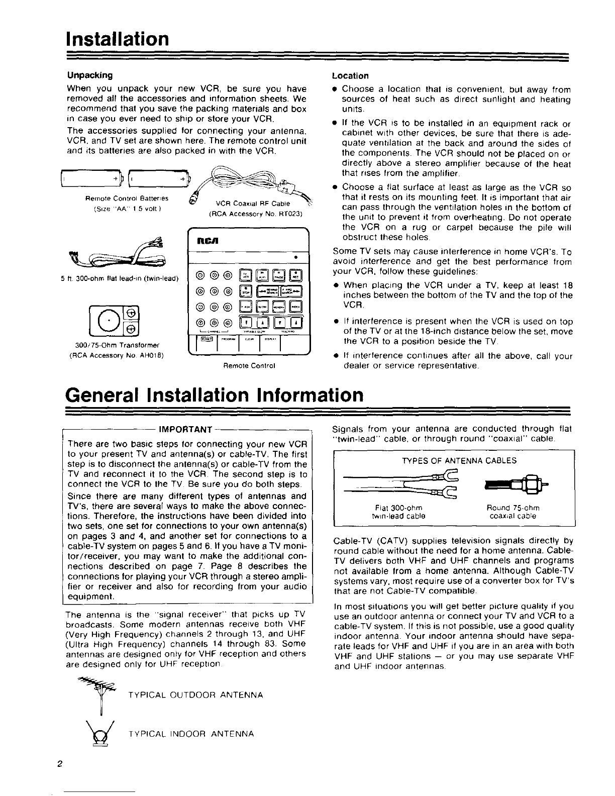
The accessories supplied for connecting your antenna,
VCR, and TV set are shown here. The remote control unit
and its batteries are also packed in with the VCR
Remote Control Batteries _7 VCR Coaxial RF Cable _
_Size 1 5 volt )(RCA Accessory NO RT023)
5 fl 300-ohm flat lead-in (twin-lead)
300/75=Ohm Transformer
(RCA Accessory No AH018)
IIICA
®@@
Remote Conlrol
Location
•Choose alocation that is convenient, but away from
sources of heat such as direct sunlight and heating
units
• If the VCR is to be installed in an equipment rack or
cabinet with other devices, be sure that there is ade-
quate ventilation at the back and around the sides of
the components. The VCR should not be placed on or
directly above a stereo amplifier because of the heat
that rises from the amplifier
• Choose a fiat surface at least as large as the VCR so
that it rests on its mounting feet. It is important that air
can pass through the ventilation holes in the bottom of
the unit to prevent it from overheating. Do not operate
the VCR on a rug or carpet because the pile will
obstruct these holes
Some TV sets may cause interference in home VCR's. To
avoid interference and get the best performance from
your VCR, follow these guidelines:
• When placing the VCR under a TV, keep at least 18
inches between the bottom of the TV and the top of the
VCR
• If interference is present when the VCR is used on top
of the TV or at the 18-inch distance below the set, move
the VCR to a position beside the TV
• If interference continues after all the above, call your
dealer or service representative.
General Installation Information
IMPORTANT
There are two basic steps for connecting your new VCR
to your present TV and antenna(s) or cable-TV, The first
step is to disconnect the antenna(s) or cable-TV from the
TV and reconnect it to the VCR. The second step is to
connect the VCR to the TV Be sure you do both steps.
Since there are many different types of antennas and
TV's, there are several ways to make the above connec-
tions. Therefore, the instructions have been divided into
two sets, one set for connections to your own antenna(s)
on pages 3 and 4, and another set for connections to a
cable-TV system on pages 5 and 6, If you have aTV moni-
tor/receiver, you may want to make the additional con-
nections described on page 7. Page 8 describes the
connections for playing your VCR through astereo ampli-
fier or receiver and also for recording from your audio
equipment.
The antenna is the "signal receiver" that picks up TV
broadcasts. Some modern antennas receive both VHF
(Very High Frequency) channels 2 through 13, and UHF
(Ultra High Frequency) channels 14 through 83 Some
antennas are designed only for VHF reception and others
are designed only for UHF reception
TYPICAL OUTDOOR ANTENNA
TYPICAL INDOOR ANTENNA
Signals from your antenna are conducted through flat
"twin-lead" cable, or through round "coaxial" cable
TYPES OF ANTENNA CABLES
Fiat 300-ohm Round 75*ohm
twin-lead cable coaxial cable
Cable-TV (CATV) supplies television signals directly by
round cable without the need for a home antenna. Cable-
TV delivers both VHF and UHF channels and programs
not available from a home antenna. Although Cable-TV
systems vary, most require use of a converter box for TV's
that are not Cable-TV compatible.
In most situations you will get better picture quality if you
use an outdoor antenna or connect your TV and VCR to a
cable-TV system. If this is not possible, use a good quality
indoor antenna Your indoor antenna should have sepa-
rate leads for VHF and UHF if you are in an area with both
VHF and UHF stations -- or you may use separate VHF
and UHF indoor antennas
2

Antenna Connections
Disconnect Existing Antenna from TV and Connect it to VCR.
• (Your antenna will probably resemble one of the diagrams on this page.)
A, If your existing antenna is connected
to your TV like this: Disconnect the antenna from your TV and
connect it to your VCR like this:
FORUHF FROM
ANTENNA
OR t
HF OR UH F TV
YOOO
)CHANNELS 2-13)
"FI __- _-_..@L I
ll_ UHF )CHANNELS 14-83) BACK OF VCR
IFReMANT,NNA_
ADAPTER
SUPPLIED
If your existing antenna is connected
B, to your TV like this:
_UHFANo VHF_OUT D CABLE(S)
OR
VNHDFOUOHRF DISCONNECT FROM
YOUR TV
YOUR T_
VHF
UHF
Disconnect the antenna from your TV and
connect it to your VCR like this:
I_ _ADAPTER-- -- -- _ SUPPLIED
VHF
(FCRHoANNAENLSE2"13) rL_l[_--_I_"_0 0
y l /
UHF "
)C..NNELB,._,I--_
FROM ANTENNA li_ BACK OF VCP
C, If your existing antenna is connected
to your TV like this: Disconnect the antenna from your TV and
connect it to your VCR like this:
CABLE(S]
VHF_ FROM
ANTENNA
AND
UHF_ DISCONNEI_/CT FROM
YOUR TV
"_ VHF
_] UHF
IVHF {CHANNELS 2-t3)
FROM ANTENNA -- -- _ ...... I
I
rfll ,.o..
UHF )CHANNELS 14-83) .... '.....................
FROMANT_NNAL_.QL
I
D,, If your existing antenna is connected
to your TV like this: Disconnect the antenna from your TV and
connect it to your VCR like this:
BANDL_:
COMBINAT)ON SEPARATO R
VHF UHF [SPLITTER)
IVHF (CHANNELS 2 13)
FROM ANTENNA f--" _ I
YOUR TV I,i
S_PARATOR I ]]-r@ @_ r--_:-L_
)SPLITTER) I "<[" " ®'y
(Continued on next page)
3

Antenna Connections (continued)
Connect VCR to back of TV.
•(The back of your TV will probably resemble one of the diagrams below)
A, If the antenna connection on the back
of your TV looks like this: Connect the VCR to your TV like this:
v_
r
OR
OR
V_F UHF
BACK OF TV
BACK OF VCR _ N BACK OF TV
II
B, If the antenna connection on the back
of your TV looks like this: Connect the VCR to your TV like this:
VHF
VHF
_® o_
VHF
°HF
OR
vH_. w_- UHF
BACKOF TV
BACK OF VCR I I
/
ITWIN L[AD
ICABL E
(SUPPLIED_
II
BACK OF TV
C= If the antenna connection on the back
of your TV looks like this: Connect the VCR to your TV like this:
)VHF
(_U HF
_CK OIF W
I I--(:]:_:>1 rl BAc,OF,_
BAc.o..cR ' vc .lII
i ii_ ;: ::: L : :: :: z: :_ _: COAX LI I I
_[_3 .... ,• RF CABLE
L,,,
I'%WLI'pNpLL':[[_Io'
TF]ANS_ORME _
ISUPPLIED _
VHF
ROUND
TV JACK
UHF
ROUND
_/JACK
4

Cable-TV Connections
Your VCR is designed to receive unscrambled cable
channels 2 thru 13, 14 thru 36 (A-W), 37 thru 94 (W+I to
W+58), 95 thru 99 (A-5 to A-l), and 01 (A-8) without a
"converter box."
The way you interconnect your VCR and TV with a cable
system depends on (a) whether your TV is cable-compati-
ble and (b) whether any channels on your cable-TV sys-
tem are scrambled. Use the Selection Chart at the right to
determine which one of the following four Cable-TV con-
nection diagrams (A-D) you should use.
If you wish to record one or more local UHF channels that
your Cable-TV system does not offer, first follow the
appropriate cable-TV connection instructions described
below. Then connect your UHF antenna to the VCR as
described in the section titled "Antenna Connections."
IF YOUR TV IS:
cable-compatible
not
cable-compatible
AND YOUR CABLE-TV
SYSTEM HAS:
no scrambled channels
some or all channels
scrambled
no scrambled channels
some or a(I channels
scrambled
THEN USE
DIAGRAM
A
D
B orC
D
r
A. DISCONNECT CABLE FROM TV,
FROM
CAaLE
TV
SYSTEM TO
_----I_:{_----CABLE-READY TVSET
DISCONNECT FROM
YOUR TV
CONNECT CABLE TO VCR. CONNECT VCR TOW.
F.OM
CABLE W----
SYSTEM
NO
UHF
CONNECTIONS
L_t
IRF CABLE
(SUPPLIED)
_CK OF VCR mmmam
=1
_w JACK
IIIIIL
BACK OF TV
DO NOT CHANGE
DISCONNECT CABLE TV ORIGINAL CONNECTION
• FROM CONVERTER CONNECT CABLE W TO VCR. CONNECT VCR TO CONVERTER. FROM CONVERTER TO TV
=.-7=. _I
,.OM I s_S.E, i '_ I_ . oo'.o. ,11:===I
CAB4.E Tn I _ I I ; _ I DISCONNECT II I i
SY_EMCONV_'RTE"I I ®II_ .,-__:ro _rh :_ II li=l I" I ' l_#_i .o_.o
I | II_-_'_ _ _.__ ivc.-1"--" I It "_W_c,x
-- ''-q=M- ....... NO r_ (_l '............. E_:::,_FCOAX'ALcABLEI-- J " |
",1/ I'l'(soo. ,EO,r- ! II,m
I
FROM | CONNECTIONS_ _ I]I I ' ' 'I I I --"
co,vE.,E.I &$ ,
,ou° I II. II
|I'BACK OF VCR m ICONVERTER BOx | BACK OF TV
When you use this set of connections, keep your TV
tuned to the channel you have been using (usually chan-
nel 3 or 4) and use the converter box as you always have
for normal TV viewing and for viewing some other chan-
nel while you are recording
When you want to view the channel you are recording, or
when you play the VCR, tune the "converter box" to the
same channel that you have set the channel switch on the
back of the VCR. either channel 3 or 4. (This is called the
"VCR channel" throughout the operating instructions in
this manual)
Special CATV Adapter
Your VCR has a connector for a"CATV Adapter" (RCA
CADO30) which you may purchase as an accessory. Con-
necting cables and installation instructions are included.
Among its features are:
•It simplifies the use of your VCR with a TV set being
operated with a converter/descrambler.
• VCR timer recording and recording one channel while
watching another is possible for both regular and
scrambled channels.
• A TV game can be included for electronic switching
without changing connections.
• A built-in high performance booster reduces signal
lOSS.
•See page 33 for more information.
(Continued on next page)

Cable-TV Connections (continued)
-C.
When you use these connections the A-B switch is used
to select either the converter output or the VCR output
0Disconnect Cable-TV from converter.
O Disconnect TV from converter cable
Connect Cable-TV to input of splitter
C<)NVE RF[ R 8Ox |
0...._%_,_,"%'_'_'1
S IG_A •
_ROM SpUr"EA
c_E
CABkE$
This arrangement will let you use your VCR as a "remote-
controlled converter box" when you are not recording.
Connect splitter to converter O Connect VCR to A-B switch
Connect splitter to VCR OConnect A-B switch to TV
Connect converter to A-B switch
AH02e
•OSWITCH"
o o
II
vH_
RO_JNO
r_ jaC_
= Optional accessory available from your RCA Dealer
Use "A" Position of A-B Switch For:
•Viewing any cable-TV channel while you record some other
channel with the VCR
• Viewing all scrambled channels
• Viewing cable channels when the VCR is turned off (Cable
channels 2 through 13 can also be viewed with the VCR turned
off and the A-B switch set to position "B ")
Use "B" Position of A-B Switch For:
•Playing a recording
• Viewing a nonscrambled channel at the same time you are
recording it (channel selected with the VCR tuner)
• Using the VCR remote control to select channels for wew_ng
when the VCR is not recording
Note: When you set the A-B switch to -Bi' tune your TV to the same channel that you have selected on the back of your VCR (3 or 4)
This is called the "VCR channel" throughout this manual.
D,
This system requires two "converter boxes" from your charge All channels must be selected with the converter
cable-TV company, and there may be an additional boxes, both for recording and normal TV viewing
Disconnect Cable-TV from converter Oconnect splitter to each of the converters OConnect VCR to A-B switch
Disconnect TV from converter cable O Connect one converter to A-B switch OConnect A-B switch to TV
Connect Cable-TV to input of splitter _Connect other converter to VCR
CONVE_T[_ _OX
c_e
s_steu I I co_v_te_ C_oue
O_JGINAL
.... £RT_ BOX _ 8_W12/_ H '
I - . F'q
Y tT
CO_Ve_E_ eOX -- BACK OF VCRm I,
0
v_
• Optional accessory available from your RCA Dea_er
Use "A" Position of A-B Switch For:
•V_ewmg any cabte TV channel while you record some other
channel with the VCR
• V_ewing any cable-TV channel when your VCR _s turned oft
Use "B" Position of A-I_ Switch For:
• Playing a recordmg
• Viewing any channel at the same time you are record=ng =t
Select the channel with the converter that is connected to the
VCR, and tune the VCR to the output channel of the converter
(usually 3 or 4)
Note: When you set the A-B switch to 'B.' tune your TV to the same channel that you have selected on the back of your VCR(3 or 4)
IThis =scalled the "VCR channel" throughout this manual
6

TV Monitor/Receiver Connections
-Direct Video and Audio Connections
Connecting the video output of your VCR to the video
input jack of your TV monitor/receiver may produce a
slightly better picture during playback. This "direct" sig-
nal connection bypasses the TV tuner during playback.
If your TV monitor/receiver has a stereo amplifier for TV
sound, connect the stereo audio outputs from the VCR to
the stereo audio input jacks of the TV monitor/receiver as
shown in the drawing on this page. Both the video and
audio connections are necessary so that you can hear
stereo sound when you play a stereo cassette, and when
you are viewing and recording the same channel.
If your TV monitor/receiver does not have a stereo ampli-
fier, you will probably want to connect the audio output
from your VCR to your stereo amplifier or receiver. The
instructions are on the next page.
STEREO AUDIO CABLE /
(not supplied)
such as RCA #RV016 _
I AUDI O TO HI-El !
@ @
lh
t
v
I--
@
FROM HOME VHF ANTENNA
OR ABLE-TV
TEM
r _.,j-- Note: If you have a
_s (._ non-stereo monitor with
j only one audio input,
1connect a single
_MONO Lcable such as RCA #AHO02 _
2 to either of the
VCR's AUDIO OUT
@ @ acks.
TYPICAL STEREO
TV MONITOR RECEIVER
SIGNAL SPLITTER
f (not supplied)
such as RCA #AH02O*
ANTENNA
CONNECTIONS
ON TV
UHF
FROM HOME
ANTENNA SYSTEM
(USED ONLYIF YOU
HAVE HOME UHF ANTENNA}
TO UHF ANTENNA
CONNECTIONS ON TV
-- (USED ONLYIF YOU
HAVE HOME UHF ANTENNA)
"Optional accessor-/ avadable from your RCA dealer
Operating Instructions
•For normal VHF or cable-TV viewing independent of the
VCR, use the TV monitor/receiver's TUNER INPUTand
select channels with the monitor/receiver's tuner.
• For viewing the channel being recorded, use the TV
monitor/receiver's VIDEO INPUT and select the chan-
nel with the VCR tuner.
•For recording one channel while viewing another, use
the TV monitor/receiver's TUNER INPUT. Use the VCR
tuner to select the channel to be recorded. Use the TV
monitor/receiver's tuner to select the channel to be
viewed
• For playing a cassette, use the TV monitor/receiver's
VIDEO INPUT
7

Stereo Amplifier Connections
Playback Connections
•Stereo sound from your video cassettes can be played
by connecting the VCR to the stereo amplifier/receiver
of your audio equipment. These connections will also
let you enjoy broadcast stereo TV by using the VCR's
stereo tuner to receive the station. You can listen to the
broadcast stereo sound, whether or not you choose to
record the program.
• Some stereo amplifiers and receivers have two sets of
"TAPE" jacks, one set for an audio tape deck and
another set for a VCR. If your amplifier has both sets,
connect your VCR to the set of jacks for the VCR. Fol-
low the instructions in your amplifier/receiver owner's
manual. If your stereo amplifier does not have aset of
jacks for a VCR, use the following instructions and
diagram.
• The connector panel shown in the drawing is typical of
many amplifiers; however, the locations of the jacks
and the number of inputs and outputs will vary. Read
the ampfifier/receiver manual before connecting your
VCR.
• The cable leading from the AUDIO OUT jacks on the
VCR to the TAPE PLAY jacks on the amplifier is for
playing your VCR through the stereo amplifier. Follow
the instructions in your amplifier/receiver owner's man-
ual for playing sound from a tape recorder.
• A stereo audio cable is shown in the drawing. The con-
nectors on it are color coded: RED for the right channel
and WHITE for the left channel. You can use single-
conductor cables if you prefer (RCA ._ AH002). In all
cases be sure you connect left output to left input and
right output to right input.
•If you already have a tape deck connected to the tape
inputs on your amplifier, and you want to connect your
VCR to the amplifier for playback only, you can use
another input such as AUX, TUNER, or CD.
®!
II
© @ J--.r_o,_
r@@1
t
TYPICAL
STEREO
AMPLIFIER
©
©
PHON@ _U_ER
CA_....... o_ _ _
STEREO AUDIO CABLE
!_A(not supplied) SUCH
__PARTNO. RV016
_EC PlAY @
Recording Connections
• You can use your VCR to record- stereo sound from
your amplifier/receiver by connecting them as shown
at the right. Stereo audio alone can be recorded with
your VCR, or you can record stereo audio from the
amplifier/receiver along with video from a TV broad-
cast (TV/FM simulcast).
• Some stereo amplifiers and receivers have two sets of
jacks, one set for an audio tape deck and another set
for a VCR. If your amplifier has both sets, connect your
VCR to the set of jacks for the VCR. Follow the instruc-
tions in your amplifier/receiver owner's manual. If your
stereo amplifier does not have a set of jacks for a VCR,
use the following instructions and diagram.
• The connector panel shown in the drawing is typical of
many amplifiers; however, the locations of the jacks
and the number of inputs and outputs will vary. Read
the amplifier/receiver manual before connecting your
VCR,
• The cable leading from the TAPE REC jacks on the
amplifier to the AUDIO IN jacks on the VCR is for
recording the sound you have selected with the ampli-
fier's input selector switch. Follow the instructions in
your amplifier/receiver owner's manual for recording
sound from the amplifier.
A stereo audio cable is shown in the drawing. The con-
nectors on it are color coded: RED for the right channel
and WHITE for the left channel. You can use single-
conductor cables if you prefer (RCA _ AH002). In all
cases be sure you connect left output to left input and
right output to right input.
®
TYPIC
STEREO
AMPLIFIER
..... ©Q
,D_PT
r@@l
_,_ UM_ OUTmW
STEREO AUDIO CABLE
(not supplied) SUCH
AS RCA PART NO. RV016
©
©
PHQNO
HCC
VHF O
©

What Your VCR Will Do
Broadcast/Cable Frequency-Synthesis Tuner
Provides accurate selection of VHF/UHF TV channels or
up to 99 unscrambled cable channels. _Quartz-controlled
electronics automatically lock the system onto the signal,
eliminating the need for fine tuning. Bright, easy-to-read
channel display.
"'Local systems may vary; check your cable company's
compatibility requirements.
Auto Programming
Preset available channels into VCR's electronic scan
memory at the touch of a single button. Eliminates cum-
bersome manual programming steps. After automatic pro-
gramming, channels can be selected by remote control
scanning -- either up or down. Add and Erase buttons
also are included for tailoring memory scan list to per-
sonal preference.
Broadcast Stereo Recording Capability with Bilingual
Audio Channel Reception (SAP)
Receive and record stereo sound from BTSC stereo TV
broadcasts, where available -- no modification or special
equipment is required. External stereo system or compati-
ble stereo TV required for stereo playback.
Also lets you record broadcast stereo while at the same
time recording the bilingual (SAP) channel, where avail-
able. Choose either standard or bilingual channel on
playback.
8-Hour Recording Time
Up to eight hours of uninterrupted record/playback time
are available in SLP mode with the RCA T-160 cassette.
During VHS Hi-Fi recording, that's comparable to ten or
more LP albums -- long enough to preserve hours of
music on a single tape without the need to change sides.
Standard Play (SP) and Long Play also are included to
ensure compatibility with all VHS-format tapes. VCR auto-
matically selects correct playback speed. LED indicators
signal tape speed.
VHS HI-FI Stereo
VHS Hi-Fi is atechnological breakthrough that delivers
amazingly lifelike high fidelity stereo reproduction at all
three tape speeds with a dynamic range of more than 80
dB. (Conventional VCR's, by comparison, approach only
45-55 dB.) The secret is in the headwheel, which contains
two audio heads in addition to the video heads. Audio sig-
nals therefore are recorded at the same speed as video
signals -- a rate over a hundred times faster than conven-
tional audio recording. As a result, playback audio
approaches the quality of advanced digital audio.
Plays all standard prerecorded VHS tapes, whether stereo
or mono. Stereo audio outputs permit hook-up to an
external audio system or stereo TV. Stereo audio inputs
make Hi-Fi recordings from an external system possible at
home -- even without a video signal. Automatic level con-
trol (ALC) self-adjusts recording levels. Also features
right/left slide controls and illuminated peak indicators
for manual recording level adjustments.
Sound-with-Sound Audio Dub
Without affecting the Hi-Fi soundtrack, new audio can be
recorded onto the linear sound track of a previously rec-
orded cassette, erasing original linear audio. Optional
microphone or external audio system required. On play-
back, Hi-Fi track, linear track, or mix of both may be
chosen.
VHS HQ Picture Quality
This VCR incorporates VHS HQ (High Quality) circuitry for
improved picture quality. It is fully compatible with earlier
VHS VCR's.
Infrared Remote Control
Provides wireless VCR control from the comfort of an
easy chair. This VCR can also be operated with an RCA
Digital Command remote control and integrated into a
unified RCA audio/video system.
Remote Programming with On-Screen Display
With RCA's advanced remote control, all VCR timer pro-
gramming can be done from across the room. At the
touch of a button, simple easy-to-follow instructions
appear on TV screen to guide the viewer through each
programming sequence. Built-in computer memory can
be preset up to a year in advance to record as many as
eight programs automatically. Backup circuitry retains
programming instructions to prevent VCR memory loss in
case of brief power interruptions.
Delayed-Start Express Recording (XPR)
Two touch-buttons permit automatic timer recording with-
out the need for numerous programming steps. Just enter
starting time and length of desired program up to 24
hours before it airs. VCR will turn on at the correct time,
record the program and automatically shut off.
On-Screen Display Graphics
Vivid display appears on TV screen to provide visual con-
firmation of commands to VCR. Includes day/date, time,
channel, as well as on-screen tape counter to indicate rel-
ative position of programs on cassette. Counter memory
automatically stops tape at desired point during rewind or
fast forward.
"Field-Still" Video System with Jitter-Free Special
Effects (SP and SLP modes)
Sophisticated 5-head record/playback system with jitter-
free "field-still" video performance provides these special
effects in SP and SLP modes: Forward and Reverse
Search; Stop Action; Frame Advance; Variable Speed
Slow Motion.
Electronic Program Indexing
Simplifies finding start of recorded programs by automati-
cally encoding an electronic signal on the tape at begin-
ning of each new recording. During Fast Forward or
Rewind, the VCR will stop at each encoded signal, pre-
view a brief segment in Play mode and continue to next
signal. When desired point is reached, simply press PLAY
for normal viewing.
Automatic Rewind
Cassette is rewound automatically when end of tape is
reached. If VCR is turned off during rewind, it will finish
rewinding the cassette before shutting off. (To prevent
accidental erasures, Auto Rewind is not operative in
"Timer" mode.)
Scene Transition Stabilizer
Minimizes picture break-up that can occur when pause
control is used during recording. Result is smooth transi-
tion between taped segments.
Headphone Jack
Optional headphones can be plugged into VCR for private
stereo listening during recording or playback,
Unswitched AC Outlet
Power additional audio or video components (maximum
300 watts) directly from the VCR Components plugged
into outlet operate regardless of whether VCR is on or off.
Helps minimize cords at wall outlet. 9

Basic Operation
0 0 0 000 00000
Now that you have connected your VCR to your "IV and _)
antenna or cable-TV system, you are ready to turn it on.
You don't need to know all the details about the controls
and display before you begin using your new VCR, so _)
only those you will use for basic recording and playback
are discussed here. Additional information about the con- _)
trois is on pages 16-17.
Basic Operating Controls and Displays _)
POWER: Turns the VCR on and off.
EJECT: Ejects the cassette from the VCR.
CASSETTE COMPARTMENT AND INDICATOR: (_
Instructions for inserting and removing cassettes are _)
at the bottom of this page. The indicator is on when a
cassette is in place.
_) STOP: Stops whatever the VCR is doing (Record,
Play, Rewind, Fast Forward, and Special Effects
described on page 17).
0RECORD: Press RECORD and PLAY at the same
time to begin recording.
(_ PLAY: Starts playback.
VCR/TV SWITCH: Selects the signal source that is _)
fed to your TV. When the light above the button is
off, your TV receives signals from your VHF antenna
or from the cable-TV system. When the light is on, _)
signals come from the VCR tuner or the tape that is
playing. (This switch is called the "VCR/'FV switch" _)
in this manual to avoid confusion with the VCR
itself.)
0Hi-Fi INDICATOR: Lights when VHS Hi-Fi sound is
being played back.
Inserting and Removing Cassettes
TIME DISPLAY: The time is normally shown here. If
the clock has stopped you will see "--:--" in this
area.
CHANNEL DISPLAY: Shows channel to which VCR
is tuned.
ALC INDICATOR: Lights when Automatic Level Con-
trol is turned on (switch (_)).
CHANNEL: • selects the next lower channel and •
selects the next higher channel. (Channels must first
be programmed -see next page.)
TAPE SPEED INDICATORS: Show tape speed
REW "<< F.FWD >.1_:Press REWto rewind the tape
when the VCR is stopped. Press F.FWD to fast for-
ward the tape. Pressing these buttons while the VCR
is playing causes the VCR to search backward or for-
ward thru the tape.
(_ CHANNEL PROGRAMMING: See "Programming
Active Channels into the VCR Tuner" on page 11,
(_ DIMMER: Alternately produces a bright or dim
display,
TAPE SPEED: Selects tape speed for recording. The
lighted indicators (_) ) show the tape speed during
recording and playback. Use SLPfor now.
HI-FI/MIX/LINEAR: Set this switch to Hi-Fi for nor-
mal playback.
ALC ON/OFF: Alternately turns the ALC (Automatic
Level Control) on and off. Turn on the ALC(indicator
_) on) for normal recording.
TUNER/SlMULCAST/LINE: Be sure it is set to
TUNER for recording TV programs.
To Insert: Turn on the VCR and then
push the cassette through the door
until the VCR mechanism pulls it into
the compartment. Light Oturns on
when the cassette is in place,
To Eject: Power must be on to eject the
cassene Rewind the cassette before
electing it Press EJECT
To Remove; The cassette will come
partially out of the compartment so you
can pull it out Put the cassette mits
box and store _t upright
10

Basic Operation (continued)
Turning on Your VCR for the First Time
When you have finished connecting the cables to your
antenna and TV, plug in the VCR's power cord and press
POWER. The light in the STOP button should come on. If
it flashes, too much moisture has collected inside the unit
for it to operate. Leave the VCR turned on until the inter-
nal heat dries it and the light stops flashing. Proceed
below when the light in the STOP button is on and not
flashing.
Programming Active Channels Into the VCR Tuner
The AUTO PROG (Automatic Programming) button
makes it simple to program TV stations into the VCR's
scan list. The scan list isthe list of channels that your VCR
tuner stops on when you press the CHANNEL • or CHAN-
NEL • button. The scan list is empty, however, until you
program active channels as described below.
Note: You must program the tuner as described below
before you can use the CHANNEL •/v buttons.
Automatic programming is usually a "one-time" proce-
dure, but you will need to repeat it if you move to a loca-
tion that has different channels, or if power is interrupted
for an extended period.
To program active channels:
1. Turn on the VCR by pressing the POWER button.
2. Set the NORM/CATVswitch on the back of the VCR
to the NORM position if your VCR is connected to a
home antenna system. Set the switch to the CATV
position if your VCR is connected to a cable-TV
system.
Note: Your VCR was shipped from the factory with the
switch set to NORM.
CHANNEL SELECT/LOCK
PROGRAMMING I_
AUTO p_OG ERASE
3. Press and release the SELECT/LOCK button. The
channel number will begin flashing.
4. Press and release the AUTO PROG button.
The tuner will automatically search through all the
channels and place the channel numbers it receives
in the scan list. This takes about a minute. The chan-
nel number in the display will stop changing when
the tuner is finished searching.
5. Press SELECT/LOCK.
The channel number will stop flashing, and Auto-
matic Programming is completed. Now you can use
the CHANNEL • and •buttons to select channels.
6. Now turn on your TV and adjust it to view what the
VCR tuner is receiving, as explained in the next
column.
7. After you have set up your TV to view the VCR, you
may want to delete channels from the scan list, or
add channels to it. The instructions are on the nexl
page.
Notes:
•Channel numbers flash when the SELECT/LOCKswitch
is in SELECT, and the CHANNEL •/V buttons will
select every channel, whether or not it is in the scan list.
• Channel numbers do not flash when the SELECT/LOCK
switch is in LOCK, and the CHANNEL •/• buttons will
select only those channels that are in the scan list.
Setting Your TV to the VCR Channel
The "VCR Channel" is the TV channel you use for view-
ing what the VCR is recording or playing, and for viewing
the signal from VCR tuner when it is stopped. Your TV
must be set to this channel, and the VCR light above the
VCR/TV switch on your VCR must be on.
Selecting the VCR Channel is normally a one-time proce-
dure, since there is little reason ever to change it. Pro-
ceed as follows:
1. Be sure the TUNER/SIMULCAST/LINE switch
behind the auxiliary control door is set to TUNER.
2. Decide whether you want to view your VCR on Chan-
nel 3 or Channel 4 of the TV. If one of these channels
is vacant in your area, you should use it. Otherwise,
pick the channel you view less.
3. Set the channel switch on the back of the VCR to
whichever channel you have chosen.
4. Turn on your TV and tune it to the same channel.
This is the "VCR Channel."
Setting the VCR/TV Switch
1. Push the VCR/TVswitch so that the VCR light is on.
When the tight is on, the VCR is in the "VCR Mode"
and your TV must be tuned to the VCR channel
(channel 3 or 4), Your TV will then display the tape
that you are playing or whatever channel the VCR is
tuned to.
2. Push the VCR/TVswitch again so that the VCR light
is out. When the light is out, the VCR is in the "TV
Mode," and your TV will work like it did before you
connected the VCR.
The VCR/TV switch allows you to record one program
with the VCR while you watch another program on your
TV. To do this, first put the VCR in the "VCR Mode" (light
on) and start recording the program. Then press the
VCR/TV switch to go to the "TV Mode" (light out) and
tune your TV to whichever channel you want to watch.
Note: Your VCR automatically switches to the "VCR
Mode" (VCR light on) when you turn it on with the
POWER button, and when you start playing a tape.
11

Basic Operation (continued)
t •
Simplified Installation Checklie
Usethts _heckiist to determine quickly if you have com-
pleted all the steps for nstallation and basic operation.
[ ] 'Make sure your VCR is conneCted properly as
explained on pages 2-8_
[ ] Press POWER to turn on the VCR.
[ ] Set the NORMICATV switch on the back of the VCR
to NORM if you have ahome antenna system. Set
the switch to CATV if you have cable TV.
[ ] Program active channels into the VCR's scan list.
Press SELECT/LOCK, press AUTO PROG, wait about
one minute, and t_en press SELECTILOCK again.
and VCRlight.
Deleting Channels from the Scan List
You may want to have only a few favorite channels in the
scan list so you can select them more quickly with the
CHANNEL • AND • buttons. (Use the numbered buttons
on the remote control to select channels you have deleted
from the scan list.) Occasionally Automatic Programming
may include a blank channel in the scan list if there hap-
_ened to be some sort of "noise" or "stray signar" on the
channel when the tuner was programmed.
Use this procedure to delete any unwanted channels from
the scan list:
t. Use the CHANNEL • or • button to select the chan-
nel that you want to remove from the scan list.
2. Press SELECT/LOCK. The channel number will
begin flashing.
3. Press ERASE.
The sound will go oft, which tells you that the chan-
nel number has been deleted from the scan list.
4. Press SELECT/LOCK again.
This returns the tuner to normal operation. The
number will stop flashing and will no longer be in the
scan list.
5. Repeat this procedure for each channel you want to
delete from the scan list.
Notes:
•Channel numbers flash when the SELECT/LOCKswitch
is in SELECT, and the CHANNEL A/• buttons will
select every channel, whether or not it is in the scan list.
•Channel numbers do not flash when the SELECT/LOCK
switch is in LOCK, and the CHANNEL A/• buttons will
select only those channels that are in the scan list.
Adding Channels to the Scan List
You may have deleted a channel from the scan list and
want to put it back. Occasionally Automatic Programming
may "miss" an active channel because the signal is very
weak, or because the the channel happened to be "off the
air" when the tuner was programmed.
Use this procedure to put any channel in the scan list:
1. Press SELECT/LOCK. The channel number will
begin flashing.
2. Use the CHANNEL &/• buttons or the numbered
buttons on the remote control to select the channel
you want to add to the scan list. There will be picture
but no sound at this time, and the channel number
will flash.
3. Press ADD.
The sound will come on to tell you that the channel
has been added to the scan list.
4. Press SELECT/LOCK.
The channel number will stop flashing to tell you that
the tuner is in its normal operating mode.
12

Remote Control
Before you use the remote control unit supplied with your
VCR, install the batteries (instructions below). Severai of
the remote's buttons do the same things as buttons with
the same names on the front of your VCR, and you can
use whichever one is more convenient at the moment.
The remote control has additional buttons for controlling
some of the VCR's Special Effects and Features, and it is
also usecl for setting the clock and programming the
timer.
Since the remote control operates the VCR by infrared
light, it is immune to electrical and sound interference.
However, you must aim the remote unit directly at the
VCR. There cannot be any obstructions between them,
Battery Installation
The batteries supplied with your remote control are
3acked separately. To install them in the hand unit:
1. Turn the hand unit over and remove the cover of the
battery compartment.
2. Insert the batteries so that their positive (+) ends
contact the positive terminals in the battery compart-
ment. These are marked (+) in the bottom of the
compartment.
3. Replace the cover.
Replace the batteries when your VCR fails to respond to
the remote control. Replacement batteries are widely
available. Use size "AA" 1.5 volt cells. Alkaline type bat-
teries are preferred. Good batteries should last ayear or
more in normal service,
Avoid laying the remote control upside down or placing
things on top of it. This could depress the buttons and
discharge the batteries. If you are not going to use the
hand unit for a month or more, it is wise to remove the
batteries to avoid leakage.
0PAUSE: Same as PAUSE on the VCR
i_ PLAY: Same as PLAYon the VCR.
TV VCR: Same as the VCR/TV switch on the VCR.
0NUMBERED BUTTONS: Select any channel
(whether or not it is in the Tuner Scan List) by press-
ing two buttons (Press 0 and then 8 for channel 8.)
The numbered buttons are also used for setting the
clock and programming the timer.
STOP: Same as STOP on the VCR.
OF. ADV: (Frame Advance) Advances the picture from
frame to frame during stop-action viewing This is
explained on page 17.
CHANNEL •and T: Same as the CHANNEL buttons
on the VCR.
POWER: Same as POWER on the VCR
PROGRAM: Used for setting the clock and program-
ming the timer.
CLEAR: Used for setting the clock and programming
the timer. Also resets the tape counter to 0000.
_) INDICATOR: Blinks when the remote sends a corn-
mand to the VCR.
_) REC: Same as RECORD on the VCR. (Press both
PLAY and REC to begin recording.)
(_ REWIND/SEARCH <<: Same as REW/SEARCH <<
on the VCR.
F. FWD/SEARCH IHb: Same as F. FWD/SEARCH
I_1_on the VCR
_) INDEX: Turns Program Indexing on and off. See
"Electronic Program Indexing" and "Indexed Play-
back" on page 18.
MEMORY: Same as MEMORY on the VCR.
O
O
©
I ® G ®/D
O L sr I/J
r/\ o
Note: Selected models of RCA color TV receivers and
monitor/receivers feature hand units that will also
remotely control your VCR, See page 31 for details.
SLOW: Used to switch from normal playback to
Slow-Motion play. VCR must be in PLAY when
SLOW is pressed. Press PLAY to resume normal
playing speed.
TRACKING • and •: If horizontal streaks ("noise
bars") appear in the picture during Slow-Motion
Playback, press one or the other of these buttons to
move the "noise bar" up or down and out of the
picture.
VARIABLE SLOW •and •: After you have begun
Slow-Motion playback, use these buttons to
decrease or increase the Slow-Motion speed,
DISPLA Y:Controls the On-Screen Displays in a four-
step sequence. (The TV must be turned on and
tuned to the VCR channel,)
First keypress: Displays VCR status on the TV. (The
display comes on automatically whenever you
change VCR status,)
Second keypress: (Must be made before the display
disappears from the TV screen.) Erases everything
from the display except the TAPE COUNTER,
Third keypress: Turns off all the On-Screen Displays.
(This is useful if you are dubbing a tape and do not
want the On-Screen Displays to be recorded.)
Fourth keypress: Returns the On-Screen Displays to
normal operation.
13

Setting the Clock
Here are some things you should know before you set the clock:
•When you first plug in your VCR, the clock will read
H_.I._""
• The buttons for setting the clock are on the remote
hand unit.
• While you are setting the clock, the display on the TV
screen will prompt you through the procedure,
• If you press a wrong digit, press CLEAR repeatedly until
the incorrect digit flashes, and then enter the correct
digit.
•If you enter an illogical time or date (13th month for
example) a question mark will appear instead of the
illogical entry. Simply enter the Correct digit to replace
the question mark.
•The clock must be set to the correct time before you
can program the timer for unattended recordings or
use Express Recording (XPR)
• If power is interrupted tot an extended period, you wilt
have to reset the clock and re-enter your programs in
the timer,
[1]
[21
I
[31
I
I
[4]
f
[s]
Turn on your TV and tune it to the VCR Chan-
nel (channel 3 or 4). The VCR Channel is
explained on page 11.
Turn on the VCR.
Press PROGRAM on the remote hand unit
This "menu" will appear on the TV.
Press "1" to set the clock
The display prompts you to set the time. Set the time by pressing two digit buttons on
the remote for the current hour and two more
for the minute.
(For example, press 0215for 2:15.)
The display prompts you to select AM or PM. _Press "1" for AM or press "2" for PM.
The display prompts you to set the date,
Set the date by pressing six digits in order for
the month, day, and year. (For example, press
070686for July 6, 1986.)
Always press "0" before single-digit months
and days.
The day of the week will appear when you
have entered all six digits for the date
Press PROGRAMto start the clock (Note that
the display on the VCR will show the correct
time after you press PROGRAM)
Press PROGRAM again to return to the pro-
gram you were watching
14

First Recording and Playback
This page gives the basic steps for recording and play-
back. You should practice them until you can do them
without referring to the manual. To save time, we suggest
you record for only two or three minutes.
The first drawing shows how to make a recording, and the
second one shows how to play it back and turn off the
VCR. The operating notes at the bottom of the page are
keyed to the step numbers for quick reference if you have
a problem or need more information.
Making a Recording
OTURN ON TV.
OTUNE TV TO VCR CHANNEL (3 OR 4).
TURN ON VCR. INSERT CASSETTE.
_ 1 [_J STEREO Hi-Fi 1
PRESS BOTH PLAY AND RECORD.
STOP WHEN FINISHED.
SELECT CHANNEL.
\//
g, o i
o,o
o,o ,
[N_EZI_[ZZIKC3 _ o, o
o,, o
o,1 o i
[_ °_°
---= = = @
:.=10_ m i,u, t**,: =*:== = _1 _M
[] [] -.
I SET SPEED TO SLP.
SET TO Hi-Fi.
OSET TO TUNER.
TURN ON ALC.
Playtng It Back
REWIND TAPE.
START PLAYBACK.
STOP WHEN FINISHED.
_]_ STEREO Hi-Fi
,EJECT CASSETTE. REWIND TAPE.
OFF VCR. _I_TURN OFF TV.
TURN
Operating Notes
The channel switch on the back of the VCR and the
channel selector on your TV must be set to the same
channel.
If the light in the STOP button flashes, wait until it
lights continuously. This is not a problem with the
VCR A flashing light indicates too much internal
moisture is present.
Normally record at SLP. Recording speeds are com-
pared on page 20.
It may be necessary to fine tune the TV for best pic-
ture and sound. If there is no picture on the TV and
no channel numbers in the display, check that the
TUNER/SlMULCAST/LINE switch is set to TUNER.
15

Operating Controls (Detailed Descriptions)
The uses of the controls for basic operation are on page
10. Now that you are familiar with the basic procedure for
recording a TV program and playing it back, you are
ready to learn the rest of the control functions. (Buttons
described completely on pages 10-14 are not numbered
in the drawing below.)
The controls of your VCR are designed so that:
•Accidentally pressing a wrong button will not damage
the VCR or the cassette.
• Non-essential buttons are disabled during recording to
help you avoid accidental interruptions.
•Operation of the VCR is automatic whenever this is
feasible.
• Automatic recording functions (Timer and XPR) will not
disturb normal TV viewing.
•If you run out of tape during playback or normal record-
ing, the VCR rewinds it and stops automatically. If tape
runs out during Timer or Express Recording, the VCR
stops without rewinding,
• Because of these features, the functions of some con-
trol buttons depend on the condition of the VCR at the
time they are used.
O the VCR is the timer is
POWER: When turned off,
automatically turned on if it has been programmed.
When the VCR is turned on, the timer is automati-
cally turned off. Your VCR will not make a timer
recording if it is already turned on at the time.
The VCR will stop and turn off if you press the
POWER button during Recording, Playback, or Fast
Forward. If you press it during rewind, the VCR will
continue rewinding until it is finished and then turn
off.
The POWER button operates differently during Timer
and Express recording, Press POWER, STOP in that
order to stop the VCR during a Timer recording.
0EJECT: The EJECTbutton will not operate when the
VCR is recording. It will eject the cassette in any
other mode of operation.
0REW/_I,II SEARCH _'b'/F.FWD: This is the
REWIND/FAST FORWARD button when the VCR is
stopped. When you press the REWend, the VCR will
rewind to the beginning of the tape (or to a counter
reading of 0000 if memory is turned on) unless you
press STOP. When you press the F. FWD end, the
tape will continue to "fast forward" until you press
the STOP button. If you do not press the STOP but-
ton, the VCR will "fast forward" to the end of the
tape and then automatically rewind. See "Memory
Stop" on page 18.
O
This same button becomes the SEARCH button
when the VCR is playing. See "Picture Search" on
page 17.
The button is inactive during recording,
RECORD: Press both RECORD and PLAY to begin
recording when the VCR is stopped. You can switch
directly from Playback to Recording by pressing
both buttons when the VCR is playing.
O
O
PAUSE: Interrupts arecording or switches from nor-
mal playback to Stop-Action. Pressing PAUSE again
resumes recording or normal playback. See "Pause
During Recording" and "Pause for Stop-Action Play-
back" on page 17.
PLAY: The PLAY button is normally used to begin
playback when the VCR is stopped. It is also used to
switch from Stop Action to Slow-Motion (described
on page 17). The PLAY button is inactive when the
VCR is recording.
INDICATORS:
Hi-Fi: On when VHS Hi-Fi audio is being played back.
STEREO: On when stereo audio is being received.
The MONO light must be off before stereo can be
recorded.
MONO: Controlled by (_. All TV sound will be
received in monaural when the light is on.
AUD B: On when a Second Audio Program (SAP) is
being received. SAP will not be recorded unless the
B SET light is also on.
BSET: Controlled by (_). A Second Audio Program
(SAP) can be recorded when the light is on.
ALC: Controlled by (_. On when Automatic Level
Control (ALC) is on.
INDEX: Controlled by (_. On when Electronic Pro-
gram Indexing is on. (See page 18.)
MEMORY: Controlled by _). On when Memory
Stop is on.
TIMER: On when the Timer has been programmed
and the VCR is turned off.
LINE: Controlled by (_. On when the video and
audio input jacks on the back of the VCR have been
selected as the recording source.
A. DUB: Controlled by (_. On when Audio Dubbing
is in use.
16

Operating Controls (Detailed Descriptions)
_) AUDIO LEVEL CONTROLS AND DISPLAY: Control
and display the levels of the audio being recorded.
The controls are active only when ALC _) is turned
off. See "Automatic Level Control" on page 19.
OPHONE: Jack for stereo headphones and control for
headphone volume.
_) INDEX: Turns Electronic Program Indexing on and
off. See page 18.
(_ MEMORY: once to turn on the
Press this button
Memory Stop feature. Press it again to turn off Mem-
ory Stop. See "Tape Counter" and "Memory Stop"
on page 18.
_) STEREO/MONO: Prevents stereo reception of TV
broadcasts when you turn on the MONO light (use if
stereo sound is too noisy). When you turn off the
MONO light, the VCR tuner will receive stereo TV
when it is broadcast. See "Broadcast Stereo TV" on
page 19.
(_ Hi-Fi/MIX/LINEAR: Use the HI-Fi position for normal
playback. See "VHS Hi-Fi Sound," "Second Audio
Program," and "Audio Dubbing" on page 19.
(_ Tape to 0000. See
RESET: Resets the Counter
"Memory Stop" on page 18.
AUDIO B SET: Controls the B SET andlight permits
the VCR to record a Second Audio Program (SAP or
AUDIO B) when the light is on and an SAP program
is being received. See "Second Audio Program" on
page 19.
XPR: Complete information is on page 27.
TUNER/SIMULCAST/LINE: Selects the program
source to be recorded. The TUNER position is used
for recording from the VCR's built-in tuner. The
SlMULCAST position selects video from the VCR
tuner and audio from the AUDIO IN jacks on the back
of the VCR. The LINE position is for recording video
and audio connected to the input jacks on the back
of the recorder. When the switch is in the LINEposi-
tion, the LINE light comes on and the channel dis-
play is turned off. See page 24 for recording
simulcasts and audio only.
_) ALC: Permits manual adjustment of the audio levels
when you turn off the ALC light. See "Automatic
Level Control" on page 19.
AUD DUB: Turns the Audio Dubbing feature on and
off. See page 19.
LEVEL DISPLAY ON/OFF: Turns the level display on
and off. Does not affect the audio levels.
TRACKING: See "Tracking Control" on page 18.
_) Reset: If the indication of the
Display or operation
display appears abnormal, push the switch within the
hole located on the bottom of the VCR.
Special Effects
Pause During Recording
Press the PAUSE button when you are recording to pre-
vent recording short passages of unwanted material.
Press the PAUSE button again when you are ready to
resume recording. Avoid pausing for more than three or
four minutes, because the spinning record/playback
heads are still in contact with the tape and will eventually
wear off the active material. This will cause streaks or
spots in the picture when you play the worn part of the
tape (called dropouts).
Recording Speeds for Special Effects
All of the following Special Effects are designed for use
at either SP or SLP speed. Although they may be used
with tapes recorded at LP speed, the picture will not be
as good as for tapes recorded in SP or SLP.
Pause for Stop-Action Playback
Press the PAUSE button during playback to stop the
action. This lets you examine all the details of the scene,
similar to looking at a single frame of a movie film. When
you are ready to resume normal playback, press the
PAUSE button again.
• The stop-action picture may tend to jump up and down
slightly. Adjust the control marked V LOCK on the back
of the VCR to reduce this jitter.
• Using stop-action on a single frame of the picture for a
long time can wear the tape, as explained in "Pause
During Recording" above. Use STOPinstead of PAUSE
to interrupt playback for an extended time. The VCR
will automatically switch from Pause to Stop after five
minutes.
Frame Advance
Frame Advance lets you view one Stop-Action "frame"
after another. Press PAUSE to begin stop-action viewing.
Then press F. ADV on the remote control each time you
want to go on to the next "frame" of the scene. Press
PAUSE to resume playback at normal speed.
Slow Motion
While the tape is playing at normal speed, press SLOWon
the remote control to begin slow-motion viewing. If you
are using Stop-Action viewing (Pause during Play) press
PLAYto begin Slow Motion. To return to normal playback
speed, press PLA Yagain. Sound is turned off during slow
motion.
The VCR will automatically switch from slow motion to
normal play after about five minutes.
It is normal to occasionally see some streaks in the pic-
ture during slow motion. Use the TRACKING buttons on
the remote control to move them up or down and out of
the picture.
Picture Search
The REWIND/FAST FORWARD button becomes the
SEARCH button when you are playing atape. When you
press the end marked I_., the VCR plays at a higher
speed until you release the button. When you press the
end marked <4, the VCR reverses from the normal direc-
tion and plays the tape backward at high speed until you
release the button. The sound is turned off during picture
search because it would not be understandable at the
high speed. Expect to see some horizontal lines in the
picture when you are searching.
17

Special Features
Memory Stop
Press MEMORY to turn on Memory Stop. Now the VCR
will stop automatically at 0000 whenever you use REWIND
or FAST FORWARD. (Simply press the REWIND button
again to rewind to the end of the tape.) If you press FAST
FORWARD and the counter never reads 0000 between
that point and the end of the tape, the VCR will continue
to the end of the tape, switch to Rewind, and then stop
when the counter reads 0000.
Since you can reset the counter to 0000 at any point on
the tape, Memory Stop is convenient for "marking" the
beginning of a recording you are going to make, and for
finding the part of a recording you want to repeat.
Use this procedure when you want to begin recording
somewhere beyond the start of the tape.
1. Turn on the VCR.
2. Use F. FWD and STOPto locate the point where you
want to begin recording.
3. Press the DISPLAY button on the remote twice so
that the counter is displayed on the screen.
4. Press MEMORY on the remote
to turn on memory stop. (An
"M" will appear on the screen
below the counter reading
whenever memory stop is on.)
Note: If you press MEMORY
again, the "M" will disappear
and the memory stop feature will
be turned off,
5. Press CLEAR on the remote to reset the counter to
"0000".
6, When you are finished recording, press STOP then
REWIND. The cassette will rewind until the counter
reading reaches "000O".
7. You can now press PLAY to view the segment you
have selected ... or press REWIND again to rewind
the cassette completely.
Use this procedure during playback to mark a point to be
repeated.
1. When you see the beginning of the part you want to
view repeatedly, press the CLEAR button on the
remote. This resets the counter to "00O0" and shows
it on the screen.
2. If the "M" is not showing under the counter reading,
press MEMORYto turn on the Memory Stop feature.
3. When you have played to the end of the scene, press
STOP and then REWIND. The tape will rewind until
the counter reading is "0000" and then stop.
4. Press PLAYto view the scene again.
5. Repeat steps 3 and 4 as many times as you like.
Tape Counter
You can also use the tape counter for making an index of
programs on a tape. Simply press DISPLAYon the remote
to display the counter and press CLEAR when the tape is
completely rewound. Then note the counter reading at
the beginning of each program, A label kit is provided
with RCA tapes for listing programs and counter readings.
Electronic Program Indexing
This indexing method causes electronic "marks" to be
recorded on the tape at each point where you begin
recording. Later, the VCR can find these "marks" auto-
matically, making it easy to find the beginning of each
program for playback. Since these indexing points are
permanent (until the tape is erased) they are not lost when
the counter is reset or the cassette is removed from the
VCR. Program Indexing is especially useful if you record
audio only, since sound is muted during normal Picture
Search.
An index mark is recorded automatically each time the
VCR goes from STOPto RECORD. If you wish to make an
index mark in the middle of a recording, you must press
STOP then PLAY and RECORD to restart the recording
and make the index mark.
Note; Using PAUSE for a momentary interruption in a
recording does not generate an index mark. If two pro-
grams are to be recorded and one immediately follows the
other, you must press STOP and then press both REC-
ORD and PLAY if you want to insert an index mark.
Indexed Playback
The tape must have been indexed beforehand. An
indexed tape can be played without using Indexed Play-
back if you choose.
1. Prepare to play the tape in the usual manner, and
then turn on INDEX (indicator light on).
2. Press F FWD if the tape is completely rewound. Oth-
erwise press either F FWD or REWIND, depending
on the direction you want to search. The tape will
"fast forward" or rewind until an index mark is
reached. When the VCR finds an index mark, it plays
for approximately ten seconds so you can identify
the program, and then resumes fast forward or
rewind to the next index mark.
3. Press PLAY when the desired program has been
located.
4. To rewind or fast forward the tape without stopping
at the index marks, turn off INDEX and then press
REWIND or F.FWD.
Tracking Control
When you play tapes that were not recorded on the same
VCR, streaks may appear in the picture, or VHS Hi-Fi
sound may be noisy. Adjust the TRACKING CONTROL,
located behind the auxiliary control door, in either direc-
tion to correct the problem. Return it to its center position
when the tape has finished playing. The TRACKING CON-
TROL only affects tape playback. It has no effect during
recording.
18
Table of contents
Other RCA VCR System manuals
Popular VCR System manuals by other brands

Panasonic
Panasonic Omnivision PV-2905 operating instructions

Panasonic
Panasonic AG5210 - VIDEO CASSETTE RECORDER operating instructions

Panasonic
Panasonic NV-HV65EC Service manual

Panasonic
Panasonic Omnivision PV-V4021 operating manual

Hitachi
Hitachi VT-FX950EUKN instruction manual

Philips
Philips VR750 Specifications