RCF PS 4048 User manual

OWNER MANUAL
MANUALE D’USO
PS 4048 -BACKUP POWER SUPPLY UNIT
AND BATTERY CHARGER
-ALIMENTATORE
D’EMERGENZA - CARICA
BATTERIE


TABLE OF CONTENTS
INDICE
ENGLISH
SAFETY PRECAUTIONS
DESCRIPTION
INSTALLATION
OUTPUT
CONNECTION DIAGRAMS
OPERATION
MAINTENANCE
TROUBLESHOOTING
SPECIFICATIONS
ITALIANO
AVVERTENZE PER LA SICUREZZA
DESCRIZIONE
INSTALLAZIONE
USCITA
SCHEMA DI COLLEGAMENTO
FUNZIONAMENTO
MANUTENZIONE
RISOLUZIONE DEI PROBLEMI
DATI TECNICI
4
6
6
7
7
9
10
10
11
12
14
14
15
15
17
18
18
19

4
ENGLISH
IMPORTANT
Before connecting and using this product, please read this instruction manual carefully
and keep it on hand for future reference.
The manual is to be considered an integral part of this product and must accompany it
when it changes ownership as a reference for correct installation and use as well as for
the safety precautions.
RCF S.p.A. will not assume any responsibility for the incorrect installation and / or use of
this product.
WARNING: To prevent the risk of re or electric shock, never expose this product to rain
or humidity.
SAFETY PRECAUTIONS
1. All the precautions, in particular the safety ones, must be read with special attention,
as they provide important information.
2.1 POWER SUPPLY FROM MAINS
-The mains voltage is sufciently high to involve a risk of electrocution: never install or
connect this product when its power cord is plugged in.
-Before powering up, make sure that all the connections have been made correctly and
the voltage of your mains corresponds to the voltage shown on the rating plate on the
unit, if not, please contact your RCF dealer.
-The metallic parts of the unit are earthed by means of the power cord.
An apparatus with CLASS I construction shall be connected to a mains socket outlet
with a protective earthing connection.
-Protect the power cord from damage. Make sure it is positioned in a way that it cannot
be stepped on or crushed by objects.
-To prevent the risk of electric shock, never open this product: there are no parts inside
that the user needs to access.
-The mains plug is used as the disconnect device and it shall remain readily operable.
2.2 BATTERIES
-Operating voltage is 48 V dc (therefore, it is necessary to connect in series several
batteries having a lower nominal voltage, example: 4 x 12 V).
-Always use rechargeable batteries, which need to be chosen according to the maximum
possible load.
-Verify the polarity of batteries is correct.
-Do NOT short-circuit batteries (i.e. connecting the 2 opposite poles together with
metallic wires).
-Throw empty batteries away according to your country laws about ecology and
environment protection.
3. Make sure that no objects or liquids can get into this product, as this may cause a
short circuit.
This apparatus shall not be exposed to dripping or splashing.
No objects lled with liquid (such as vases) and no naked sources (such as lighted
candles) shall be placed on this apparatus.
IMPORTANT
SAFETY PRECAUTIONS

5
ENGLISH
4. Never attempt to carry out any operations, modications or repairs that are not
expressly described in this manual.
Contact your authorized service centre or qualied personnel should any of the following
occur:
-The product does not function (or functions in an anomalous way).
-The power cord has been damaged.
-Objects or liquids have got in the unit.
-The product has been subject to a heavy impact.
5. If this product is not used for a long period, disconnect both the power cord and
batteries.
6. If this product begins emitting any strange odours or smoke, switch it off immediately
and disconnect both the power cord and batteries.
7. Do not connect this product to any equipment or accessories not foreseen.
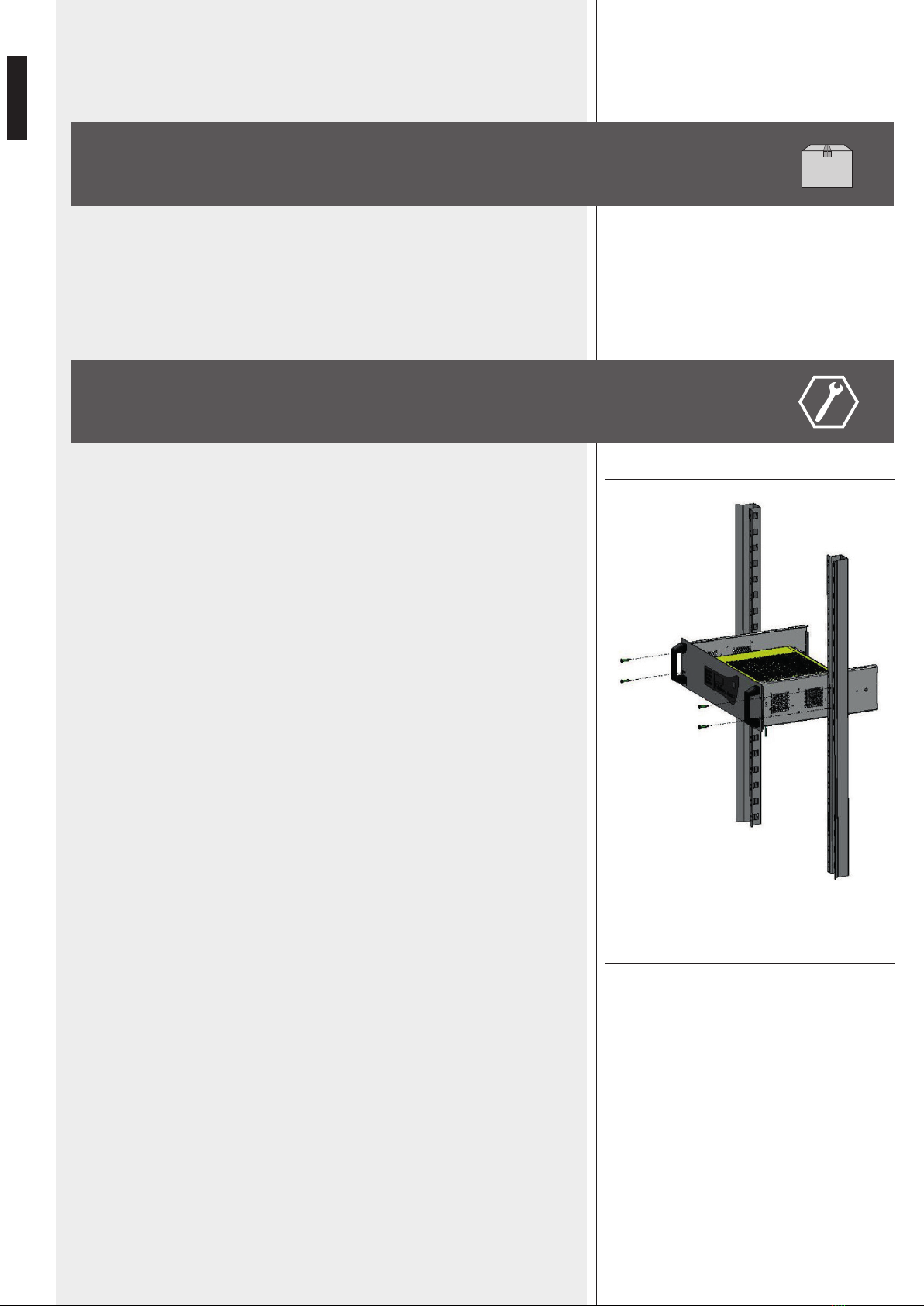
For suspended installation, only use the dedicated anchoring points and do not try to
hang this product by using elements that are unsuitable or not specic for this purpose.
Also check the suitability of the support surface to which the product is anchored (wall,
ceiling, structure, etc.), and the components used for attachment (screw anchors, screws,
brackets not supplied by RCF etc.), which must guarantee the security of the system /
installation over time, also considering, for example, the mechanical vibrations normally
generated by transducers.
To prevent the risk of falling equipment, do not stack multiple units of this product unless
this possibility is specied in the user manual.
8. RCF S.p.A. strongly recommends this product is only installed by professional qualied
installers (or specialised rms) who can ensure correct installation and certify it according
to the regulations in force.
The entire audio system must comply with the current standards and regulations
regarding electrical systems.
9. Supports and trolleys
The equipment should be only used on trolleys or supports, where necessary, that are
recommended by the manufacturer. The equipment / support / trolley assembly must be
moved with extreme caution. Sudden stops, excessive pushing force and uneven oors
may cause the assembly to overturn.
10. Do not obstruct the ventilation grilles of the unit. Situate this product far from any
heat sources and always ensure adequate air circulation around the ventilation grilles.
11. Do not use solvents, alcohol, benzene or other volatile substances for cleaning the
external parts of this product. Use a dry cloth.

6
ENGLISH
RCF S.P.A. THANKS YOU FOR PURCHASING THIS PRODUCT, WHICH HAS BEEN
DESIGNED TO GUARANTEE RELIABILITY AND HIGH PERFORMANCES.
DESCRIPTION
PS 4048 is a backup power supply unit suitable to get continuity power supply for
EN 54-16 system units (e.g. DXT 9000 and DXT 7000EN systems).
PS 4048 needs to be equipped with lead-acid batteries and includes recharging
and monitoring functions.
INSTALLATION
Fix the unit to a 19” rack cabinet through 4 screws.
According to EN 54-16 standard, the backup power supply unit shall be installed
into the same rack cabinet where there is the audio system with emergency purposes
(or a system part) to which it is connected.
19” RACK - 3U
dim.: 483 x 132 x 358 mm - IP 30

7
ENGLISH
CONNECTION DIAGRAMS
Rated output voltage: 48 V dc
Output voltage at half load (25°C): 54.4 V dc ±0.5%
Nominal output current (I n): 8 A
It is possible to link a single output or both.
The maximum overall output current that can be supplied continuously (I max a) is given by:
I n: nominal output current (8 A)
C: battery capacity [A h]
The maximum overall output current can be supplied for a short period of time (I max b,
when battery charging is not in progress) corresponds to the nominal value (8 A).
PS 4048 can operate without an output load.
The maximum overall output current (8 A) can be drawn from an output or both.
OUTPUT
I max a = I n - —
C
20
I max b = I n
F1 F7 F8
FBAT
50Ah
+-
50Ah
+-
50Ah
+-
+-
230VAC
~48-54V
12 V
+++– – –
FLT.
L N
OUT 2
TO LOAD 2 TO LOAD 1
OUT 1 BATTERIES
MAINS

8
ENGLISH
CONNECTION TO MU 7100EN (DXT 7000EN)
Use four 12V 50 Ah batteries. The PS 4048 output 1 shall be connected to the MU
7100EN 48VDC input through diodes that are needed to reduce the PS 4048 output
voltage.
Fault indications can be obtained by connecting the dedicated PS 4048 contacts to
MU 7100EN CONTROL INPUTS.
Four 12V batteries need to be linked in series (total voltage: 48 V dc) and connected to
the PS 4048 BATTERY input.
WIRE SECTIONS:
MAINS 1.5 ÷ 2.5 mm² (according to the max. load)
BATTERIES 2.5 ÷ 10 mm² (according to the max. load)
OUTPUTS 2.5 ÷ 10 mm² (according to the max. load)
FAULT DETECT. 1.5 mm²
INTERNAL MOTHERBOARD LED COLOUR:
Green: all OK
Orange: mains fault
Red: battery or charger fault or load not present (this fault has priority over a mains fault).
Fault indications can be obtained by connecting the dedicated PS 4048 (FAULT DET.)
contacts to logic inputs of the control device.
The PS 4048 properly operates when at least one of its 2 front panel green LEDs
(corresponding to the load outputs) is lit.
CONNECTION DIAGRAM TO MU 7100EN (DXT 7000EN)
87654321
SPEAKER OUTPUTS 8OHM/150W2
CONTROL INPUT
LOCALS
8765432
CONTROL OUTPUT
1
MIC/LINE INPUTOVERRIDE AUDIO OUT
LOCALSYSTEM CTRL
ALT 8x8
RS-2323,15T3,15T
100-240V
45-63Hz
40-980W
SR N:o
F1 F7 F8
FBAT
50Ah
+-
50Ah
+-
50Ah
+-
+-
230VAC
54VDC
~44-50V
~48-54V
12 V
50 Ah
1
2
3
4
5
6
7
8
9
NC
C
NO
NC
C
NO
NC
C
NO
FAULT DETECTION
MAINS
BATTERIES
OUTPUT
4 V DROP
DOWN
DIODES FLT.
OUT 2 OUT 1 BATTERIES
MAINS
+++– – –
1
5
3
7
2
6
4
8
9
nc
no
c
nc
no
c
nc
no
c
MAINS
BATTERIES
FAULT DETECTION
NC: NORMALLY CLOSED
NC: NORMALLY OPEN
C: COMMON
OUTPUT
L N
CH1 CH2 CH3 CH4 CH5 CH6 CH7 CH8 OUT IN IN
48VDC 2x7A24VDC
1 2 3 4 5 6 7 8
1 2 3 4 5 6 7
USB BUS BUS LINK
SYSTEM

9
ENGLISH
The MAINS FAULT is locally indicated by a yellow LED (on the front panel) and remotely
by its respective delayed dry contact when:
-The mains is not present or lower than 195 V ac.
-The mains fuse is blown or not present.
-The product is out of service.
The BATTERY FAULT is locally indicated by a yellow LED (on the front panel) and
remotely by its respective delayed dry contact when:
-Batteries are not present (the battery test is carried out in this way: every 30 seconds for
the rst 20 minutes after commissioning, every 15 minutes after the rst 20 minutes;
if a fault is detected, batteries will have been tested every 30 seconds for 20 minutes
after the fault disappears).
-The internal resistance is too high (a test every 4 hours on charged batteries; the
resistance limit value is 328 mΩ ±10%).
-The battery voltage is lower than 1.8 V/cell ±3%.
Voltage presence on both OUTPUT 1 and OUTPUT 2 is indicated by 2 green LEDs (on
the front panel) and a delayed dry contact..
VOLTAGE COMPENSATION
A voltage compensation system maintains the charge characteristics within the battery
limits across the entire operational temperature range.
BATTERY CHARGING CURRENT LIMITATION
The battery charging current can be set to either 100 %, 75 %, 50 % or 25 % of the
rated current by using a jumper on the daughterboard (positions:100, 75, 50, 25).
DAUGHTERBOARD JUMPER
BATTERY LOW VOLTAGE CUTOFF
The cutoff threshold is 1.8 V/cell ±3 %.
OPERATION
FRONT PANEL LEDs
MAINS
BATTERIES
OUTPUT

10
ENGLISH
In order to ensure maximal and durable service, this product needs to be installed in a dry
and ventilated location and maintained clean. RCF S.p.A. is in no case liable for damages
associated with improper use or incorrect maintenance of the equipment.
WARNING: do NOT use an incorrect type of batteries, as this may result in an explosion
hazard.
Used batteries must be disposed of in compliance with recycling requirements.
NO OUTPUT VOLTAGE:
-Check mains presence on the mains terminal strip
-Check the fuses
-Check the oating voltage (no load) on the outputs 1 and 2
-Check that each 12 V dc battery has a voltage equal or higher than 11.5 V dc
-Repeat measurements after having disconnected loads and batteries
-Check the front panel LED indications
-If all the previous steps are validated, check the load compatibility
BATTERIES DO NOT TAKE OVER AFTER A MAINS FAULT:
-Check the voltage of each single battery
-Check the battery fuse
-Check the voltage on the outputs 1 and 2
IF THE OUTPUT 1 / OUTPUT 2 LEDS DO NOT LIGHT UP:
-Check mains presence on the mains terminal strip
-Check the battery link (and the battery fuse)
-Check the voltage on the outputs 1 and 2
MAINTENANCE
TROUBLESHOOTING

11
ENGLISH
SPECIFICATIONS
RATED OUTPUT VOLTAGE:
OUTPUT VOLTAGE AT HALF LOAD (25°C):
NOMINAL OUTPUT CURRENT:
NOMINAL POWER:
OPERATING TEMPERATURE:
STORAGE TEMPERATURE:
RELATIVE HUMIDITY:
OPERATING VOLTAGE (FROM MAINS):
PRIMARY CURRENT (@ 195 V):
BATTERY VOLTAGE:
AUTHORIZED BATTERY CAPACITY:
FUSES
F1 (MAINS):
F7, F8 (LOAD):
FBAT (BATTERIES):
CPR:
STANDARD REFERENCE:
48 V dc
54.4 V dc ±0.5%
8 A
400 W
–5 ÷ +40 °C at 100 % charge
–5 ÷ +50 °C at 75 % charge
–25 ÷ +85 °C
20 ÷ 95 %
230 V ac ±15% (47 ÷ 63 Hz), class I
3 A
48 V dc (4 x 12 V)
38 ÷ 140 Ah
5x20 T8A 250V
5x20 T12.5A 250V
10.3x38 20A T
0333-CPR-075370-1, 2010
EN 54-4 (1997) + A1 (2002) + A2 (2006)

12
ITALIANO
IMPORTANTE
Prima di collegare ed utilizzare questo prodotto, leggere attentamente le istruzioni
contenute in questo manuale, il quale è da conservare per riferimenti futuri.
Il presente manuale costituisce parte integrante del prodotto e deve accompagnare
quest’ultimo anche nei passaggi di proprietà, per permettere al nuovo proprietario di
conoscere le modalità d’installazione e d’utilizzo e le avvertenze per la sicurezza.
L’installazione e l’utilizzo errati del prodotto esimono la RCF S.p.A. da ogni responsabilità.
ATTENZIONE: per prevenire i rischi di amme o scosse elettriche, non esporre mai
questo prodotto alla pioggia o all’umidità.
AVVERTENZE PER LA SICUREZZA
1. Tutte le avvertenze, in particolare quelle relative alla sicurezza, devono essere lette con
particolare attenzione, in quanto contengono importanti informazioni.
2.1 ALIMENTAZIONE DA RETE ELETTRICA
-La tensione di alimentazione dell’apparecchio ha un valore sufcientemente alto da
costituire un rischio di folgorazione per le persone: non procedere mai all’installazione
od alla connessione dell’apparecchio con il cavo dell’alimentazione collegato alla rete
elettrica.
-Prima di alimentare questo prodotto, assicurarsi che tutte le connessioni siano corrette
e che la tensione della vostra rete di alimentazione corrisponda quella di targa
dell’apparecchio, in caso contrario rivolgetevi ad un rivenditore RCF.
-Le parti metalliche dell’apparecchio sono messe a terra tramite il cavo di alimentazione.
Un apparecchio avente costruzione di CLASSE I deve essere connesso alla presa di rete
con un collegamento al conduttore di protezione (terra).
-Accertarsi che il cavo di alimentazione dell’apparecchio non possa essere calpestato o
schiacciato da oggetti, al ne di salvaguardarne la perfetta integrità.
-Per evitare il rischio di shock elettrici, non aprire mai l’apparecchio: all’interno non vi
sono parti che possono essere utilizzate dall’utente.
-La spina del cavo d’alimentazione è utilizzata come dispositivo di scollegamento e deve
rimanere sempre facilmente accessibile.
2.2 BATTERIE
-La tensione nominale è 48 V c.c. (pertanto, occorre collegare in serie più batterie aventi
una tensione nominale inferiore, es. 4 x 12 V).
-Utilizzare sempre batterie ricaricabili, opportunamente scelte in funzione del massimo
carico possibile.
-Vericare che sia rispettata la polarità delle batterie.
-Non cortocircuitare le batterie (ad esempio collegando i 2 poli opposti con un lo di
metallo).
-Smaltire le batterie esaurite facendo riferimento alle norme di legge vigenti (nel paese
di utilizzo) in materia di ecologia e protezione dell’ambiente.
3. Impedire che oggetti o liquidi entrino all’interno del prodotto, perché potrebbero
causare un corto circuito. L’apparecchio non deve essere esposto a stillicidio o a spruzzi
d’acqua; nessun oggetto pieno di liquido (quali vasi) e nessuna sorgente di amma nuda
(es. candele accese) deve essere posto sull’apparecchio.
IMPORTANTE
AVVERTENZE PER LA SICUREZZA

13
ITALIANO
4. Non eseguire sul prodotto interventi / modiche / riparazioni se non quelle
espressamente descritte sul manuale istruzioni. Contattare centri di assistenza autorizzati
o personale altamente qualicato quando:
-l’apparecchio non funziona (o funziona in modo anomalo);
-il cavo di alimentazione ha subito gravi danni;
-oggetti o liquidi sono entrati nell’apparecchio;
-l’apparecchio ha subito forti urti.
5. Qualora questo prodotto non sia utilizzato per lunghi periodi, scollegare il cavo
d’alimentazione dalla rete e le batterie.
6. Nel caso che dal prodotto provengano odori anomali o fumo, spegnerlo
immediatamente e scollegare il cavo d’alimentazione e le batterie.
7. Non collegare a questo prodotto altri apparecchi e accessori non previsti.
Quando è prevista l’installazione sospesa, utilizzare solamente gli appositi punti di
ancoraggio e non cercare di appendere questo prodotto tramite elementi non idonei o
previsti allo scopo.
Vericare inoltre l’idoneità del supporto (parete, softto, struttura ecc., al quale è
ancorato il prodotto) e dei componenti utilizzati per il ssaggio (tasselli, viti, staffe non
fornite da RCF ecc.) che devono garantire la sicurezza dell’impianto / installazione nel
tempo, anche considerando, ad esempio, vibrazioni meccaniche normalmente generate da
un trasduttore.
Per evitare il pericolo di cadute, non sovrapporre fra loro più unità di questo prodotto,
quando questa possibilità non è espressamente contemplata dal manuale istruzioni.
8. La RCF S.p.A. raccomanda vivamente che l’installazione di questo prodotto sia
eseguita solamente da installatori professionali qualicati (oppure da ditte specializzate)
in grado di farla correttamente e certicarla in accordo con le normative vigenti.Tutto
il sistema audio dovrà essere in conformità con le norme e le leggi vigenti in materia di
impianti elettrici.
9. Sostegni e Carrelli
Se previsto, il prodotto va utilizzato solo su carrelli o sostegni consigliati dal produttore.
L’insieme apparecchio-sostegno / carrello va mosso con estrema cura. Arresti improvvisi,
spinte eccessive e superci irregolari o inclinate possono provocare il ribaltamento
dell’assieme.
10. Non ostruire le griglie di ventilazione dell’unità. Collocare il prodotto lontano da fonti
di calore e garantire la circolazione dell’aria in corrispondenza delle griglie di aerazione.
11. Non usare solventi, alcool, benzina o altre sostanze volatili per la pulitura delle parti
esterne dell’unità; usare un panno asciutto.

14
ITALIANO
RCF S.P.A. VI RINGRAZIA PER L’ACQUISTO DI QUESTO PRODOTTO, REALIZZATO
IN MODO DA GARANTIRNE L’AFFIDABILITÀ E PRESTAZIONI ELEVATE.
DESCRIZIONE
PS 4048 è un alimentatore che assicura la continuità dell’alimentazione nei sistemi audio
con funzioni d’emergenza in accordo con la norma EN 54-16 (es. per i sistemi DXT 9000
e DXT 7000EN); deve essere implementato di batterie ed include le funzioni di ricarica e
controllo.
INSTALLAZIONE
Fissare l'unità al rack 19” tramite 4 viti.
In accordo con la norma EN 54-16, l’alimentatore d’emergenza deve essere installato
nello stesso rack dove è presente il sistema audio con funzioni d’emergenza (od una
sua sezione) a cui è collegato.
RACK 19" - 3U
dim.: 483 x 132 x 358 mm - IP 30

15
ITALIANO
SCHEMA DI COLLEGAMENTO
Tensione nominale d'uscita: 48 V c.c.
Tensione d'uscita con mezzo carico (25°C): 54,4 V c.c. ±0,5%
Corrente nominale (I n): 8 A
Si può collegare una singola uscita od entrambe.
La massima corrente erogabile continuamente (I max a) e data da:
I n: corrente nominale d'uscita (8 A)
C: capacità delle batterie [A h]
La massima corrente erogabile per un breve tempo (I max b, quando la ricarica delle
batterie non è in corso) corrisponde al valore nominale (8 A).
PS 4048 può funzionare senza un carico d'uscita.
La massima corrente (8 A) può essere erogata sia tramite un'uscita od entrambe.
USCITA
I max a = I n - —
C
20
I max b = I n
F1 F7 F8
FBAT
50Ah
+-
50Ah
+-
50Ah
+-
+-
230VAC
~48-54V
12 V
+++– – –
RIL. GUASTI
L N
USCITA 2
AL CARICO 2 AL CARICO 1
USCITA 1 BATTERIE
AL. RETE

16
ITALIANO
COLLEGAMENTO ALL’UNITA CENTRALE MU 7100EN (DXT 7000EN)
Usare quattro batterie 12V 50 Ah. L'uscita 1 del PS 4048 deve essere collegata
all'ingresso 48VDC dell'unità centrale MU 7100EN tramite diodi (necessari per ridurre la
tensione d'uscita del PS 4048).
Si possono ottenere segnalazioni di guasti collegando i contatti dedicati del PS 4048 agli
ingressi logici CONTROL INPUT dell'unità centrale MU 7100EN.
Quattro batterie da 12V devono essere collegate in serie (tensione totale: 48 V c.c.)
all'ingresso BATTERY del PS 4048.
SEZIONI DEI CONDUTTORI
Alimentazione da rete: 1,5 ÷ 2,5 mm² (secondo il carico max.)
Batterie: 2,5 ÷ 10 mm² (secondo il carico max.)
Uscite: 2,5 ÷ 10 mm² (secondo il carico max.)
Rilevazione guasti: 1,5 mm²
Indicazione del LED interno sulla scheda madre:
-verde: funzionamento corretto;
-arancio: guasto alimentazione da rete;
-rosso: guasto batterie / ricarica o carico non presente; questo guasto è prioritario
rispetto a quello dell'alimentazione da rete.
Si possono ottenere segnalazioni di guasti collegando i contatti dedicati (RIL. GUASTI) del
PS 4048 ad ingressi logici dell'unità di controllo.
Il PS 4048 funziona correttamente quando uno o entrambi i LED verdi sul pannello
frontale (corrispondenti ai carichi d'uscita) sono accesi.
1
5
3
7
2
6
4
8
9
nc
no
c
nc
no
c
nc
no
c
AL. RETE
BATTERIE
RIL. GUASTI
NC: NORMALMENTE CHIUSO
NC: NORMALMENTE APERTO
C: COMUNE
USCITA
87654321
SPEAKER OUTPUTS 8OHM/150W2
CONTROL INPUT
LOCALS
8765432
CONTROL OUTPUT
1
MIC/LINE INPUTOVERRIDE AUDIO OUT
LOCALSYSTEM CTRL
ALT 8x8
RS-2323,15T3,15T
100-240V
45-63Hz
40-980W
SR N:o
F1 F7 F8
FBAT
50Ah
+-
50Ah
+-
50Ah
+-
+-
230VAC
54VDC
~44-50V
~48-54V
12 V
50 Ah
1
2
3
4
5
6
7
8
9
NC
C
NO
NC
C
NO
NC
C
NO
RIL. GUASTI
AL. RETE
BATTERIE
USCITA
+++– – –
L N
CH1 CH2 CH3 CH4 CH5 CH6 CH7 CH8 OUT IN IN
48VDC 2x7A24VDC
1 2 3 4 5 6 7 8
1 2 3 4 5 6 7
USB BUS BUS LINK
SYSTEM
SCHEMA DI COLLEGAMENTO ALL'UNITÀ CENTRALE "MU 7100EN"
diodi
caduta
4 V
RIL.
GUASTI
USCITA 2 USCITA 1 BATTERIE
AL. RETE

17
ITALIANO
MAINS FAULT Presenza di un problema all'alimentazione da rete, indicato sia dal LED
giallo (sul pannello frontale) sia dal rispettivo contatto “pulito” ritardato quando:
-la tensione di rete è inferiore a 195 V c.a. (o non presente);
-il fusibile per la rete è bruciato o non presente;
-l'unità PS 4048 presenta un malfunzionamento.
BATTERY FAULT Presenza di un problema alle batterie, indicato sia dal LED giallo (sul
pannello frontale) sia dal rispettivo contatto “pulito” ritardato quando:
-le batterie non sono presenti (il test è effettuato nel seguente modo: ogni 30 secondi
per i primi 20 minuti dopo l’avviamento ed ogni quarto d’ora dopo i primi 20 minuti; se
verrà rilevato un guasto, il test sarà effettuato ogni 30 secondi per 20 minuti dopo la
scomparsa del problema);
-la resistenza interna è troppo alta (un test ogni 4 ore su batterie cariche; il valore limite
della resistenza è 328 mΩ ±10%);
-la tensione delle batterie è inferiore a 1,8 V/cell ±3%.
La presenza della tensione alla uscite OUTPUT 1 e OUTPUT 2 è indicata dai 2 LED verdi
(sul pannello frontale) e dal rispettivo contatto “pulito” (ritardato).
COMPENSAZIONE DELLA TENSIONE
Un sistema di compensazione della tensione mantiene le caratteristiche di carica entro i
limiti delle batterie (e nel campo della temperatura di funzionamento).
LIMITAZIONE DELLA CORRENTE DI RICARICA
La corrente di ricarica delle batterie può essere impostata al 100 %, 75 %, 50 % o 25 %
del valore nominale tramite un jumper (un ponticello) sulla scheda glia (posizioni:100,
75, 50, 25).
JUMPER SULLA SCHEDA FIGLIA
PROTEZIONE DA TENSIONE TROPPO BASSA DELLE BATTERIE
La soglia d'interruzione è 1,8 V/cell ±3 %.
FUNZIONAMENTO
PANNELLO FRONTALE LED

18
ITALIANO
Al ne di garantire la sua miglior funzionalità ed afdabilità, il prodotto deve essere
installato in un luogo asciutto e ventilato e mantenuto pulito. RCF S.p.A. non è in alcun
caso responsabile per i danni connessi con l’uso improprio od errata manutenzione.
ATTENZIONE: NON usare batterie non adatte, in quanto ciò potrebbe causare un rischio
di esplosione.
Le batterie usate devono essere smaltite in conformità con le norme vigenti.
NESSUNA TENSIONE DI USCITA:
-vericare la presenza dell’alimentazione (da rete) sulla rispettiva morsettiera;
-controllare i fusibili;
-controllare la tensione a vuoto (senza carico) sulle uscite 1 e 2;
-vericare che ciascuna batteria da 12 V abbia una tensione uguale o superiore a 11,5 V;
-ripetere le misure dopo aver scollegato i carichi e le batterie;
-controllare le indicazioni dei LED sul pannello frontale;
-dopo aver effettuato tutti i controlli sopraelencati, vericare la compatibilità del carico.
LE BATTERIE NON SI INSERISCONO QUANDO MANCA LA TENSIONE DI RETE:
-vericare la tensione di ogni singola batteria;
-controllare il fusibile di protezione delle batterie;
-controllare la tensione sulle uscite 1 e 2.
SE I LED “OUTPUT 1” E “OUTPUT 2” SUL PANNELLO FRONTALE NON SI
ACCENDONO:
-vericare la presenza dell’alimentazione (da rete) sulla rispettiva morsettiera;
-controllare il collegamento delle batterie (ed il rispettivo fusibile di protezione);
-controllare la tensione sulle uscite 1 e 2.
MANUTENZIONE
RISOLUZIONE DEI PROBLEMI

19
ITALIANO
DATI TECNICI
TENSIONE NOMINALE D'USCITA:
TENSIONE D'USCITA CON MEZZO CARICO (25°C):
CORRENTE D'USCITA NOMINALE:
POTENZA NOMINALE:
TEMPERATURA DI FUNZIONAMENTO:
TEMPERATURA DI STOCCAGGIO:
UMIDITÀ RELATIVA:
TENSIONE DI FUNZIONAMENTO (DA RETE):
CORRENTE ASSORBITA (A 195 V):
TENSIONE BATTERIE:
CAPACITÀ BATTERIE CONSENTITA:
FUSIBILI
F1 (ALIMENTAZIONE DA RETE):
F7, F8 (CARICO):
FBAT (BATTERIE):
CPR:
NORMA DI REFERIMENTO:
48 V c.c.
54,4 V c.c. ±0,5%
8 A
400 W
–5 ÷ +40 °C (ricarica al 100 %)
–5 ÷ +50 °C (ricarica al 75 %)
–25 ÷ +85 °C
20 ÷ 95 %
230 V c.a. ±15% (47 ÷ 63 Hz), classe I
3 A
48 V c.c. (4 x 12 V)
38 ÷ 140 Ah
5x20 T8A 250V
5x20 T12.5A 250V
10.3x38 20A T
0333-CPR-075370-1, 2010
EN 54-4 (1997) + A1 (2002) + A2 (2006)

10307386 revC
www.rcfaudio.com
HEADQUARTERS:
RCF S.p.A. Italy
tel. +39 0522 274 411
e-mail: info@rcf.it
RCF UK
tel. 0844 745 1234
Int. +44 870 626 3142
e-mail: info@rcfaudio.co.uk
RCF France
tel. +33 1 49 01 02 31
e-mail: france@rcf.it
RCF Germany
tel. +49 2203 925370
e-mail: germany@rcf.it
RCF Spain
tel. +34 91 817 42 66
e-mail: info@rcfaudio.es
RCF Belgium
tel. +32 (0) 3 - 3268104
e-mail: belgium@rcf.it
RCF USA Inc.
tel. +1 (603) 926-4604
e-mail: [email protected]
Except possible errors and omissions.
RCF S.p.A. reserves the right to make modications without prior notice.
Salvo eventuali errori ed omissioni.
RCF S.p.A. si riserva il diritto di apportare modiche senza preavviso.
2014 / 01
Manufactured by SLAT – 180130008Ba – NOT130003Ba – Ed 01/14
Table of contents
Languages:
Other RCF Power Supply manuals
Popular Power Supply manuals by other brands

HP
HP SCR-1P Series Operating and service manual

Manson Engineering Industrial
Manson Engineering Industrial HCS-3400-USB user manual

ZALMAN
ZALMAN ZM700-GVM user manual

Pulsar
Pulsar PSBS 3512C quick start guide

Manson Engineering Industrial
Manson Engineering Industrial SPA-8150 user manual

TOOQ
TOOQ TQEP-750SP user manual