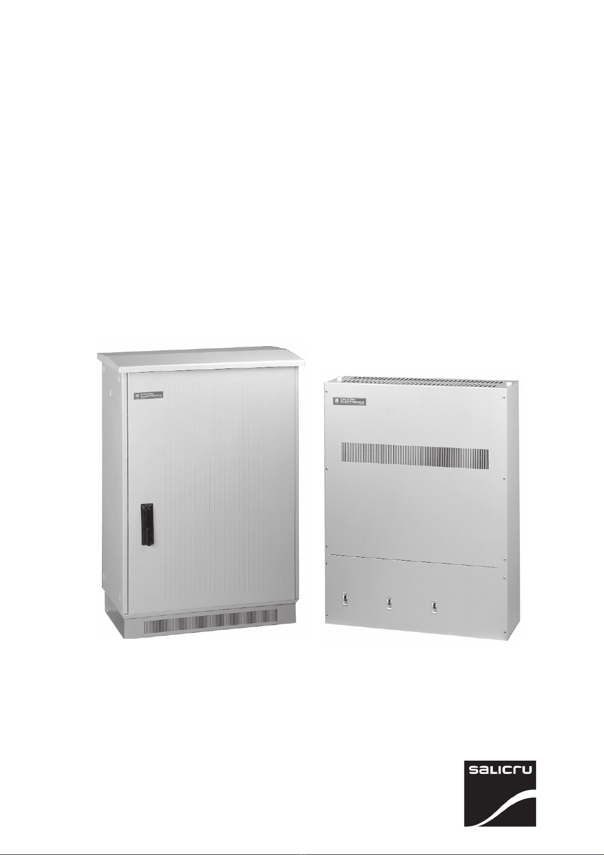
Salicru ILUEST NE Series Operation instructions

- 1 -
VOLTAGE DIMMER-STABILIZER ILUEST NE series.
STABILISATEUR-RÉDUCTEUR DE TENSION, ILUEST série NE
User’s and operating manual.
Manuel d’installation et d’opération
EK462D11

- 2 -

- 3 -
SAFETY WARNINGS ...................................................................................................... 6-8
MISES EN GARDE DE SÉCURITÉ .................................................................................. 34-36
User’s manual, installation and start up. .............................................................4-30
Manuel d’utilisateur, installation et mise en service. ......................................... 32-58

- 4 -
General contents.
1.- INTRODUCTION.
1.1.- Gratefulness letter.
1.2.- Using this manual.
1.2.1.- Conventions and used symbols.
1.2.2.- For more information and/or help.
2.- QUALITY AND STANDARD ASSURANCE.
2.1.- Management declaration.
2.2.- Standard.
2.3.- Safety and first aids.
2.4.- Environment.
3.- PRESENTATION.
3.1.- Views and legends.
3.1.1.- Legends corresponding to the views of the equipment.
3.1.2.- Frontal view.
3.1.3.- Electronic control BM478*
3.2.- Definition and structure.
3.2.1.- Nomenclature.
3.2.2.- Structural diagram.
3.3.- System description.
3.3.1.- Introduction.
3.3.2.- Constructive features.
3.3.3.- Operating principle.
3.3.4.- Versions.
3.4.- Options.
3.4.1.- Automatic bypass witch contactors.
3.4.3.- Manual Bypass.
3.4.3.- Timer.
3.4.4.- Astronomical clock.
3.4.5.- LCD display.
3.4.6.- Telemanagement pack.
3.4.7.- GSM modem.
3.4.8.- Lightning arrestor.
3.4.9.- Extended communications PCB.
4.- INSTALLATION.
4.1.- Important safety instructions.
4.2.- Equipment reception.
4.2.1.- Unpacking and contents checking.
4.2.2.- Storing.
4.2.3.- Location.
4.3.- Assembling of the different versions.
4.4.- Communication ports.
4.5.- Recommended protection devices and cross section cables.
4.5.1.- Recommended protections.
4.5.2.- Recommended cross section cables.
4.5.3.- Installation diagrams.
4.6.- Connection.
4.6.1.- Power supply connection.

- 5 -
4.6.2.- Remote control connection (saving order).
4.6.3.- Output connection.
5.- OPERATION.
5.1.- Start up and shutdown.
5.1.1.- Controls before starting up.
5.1.2.- Start up.
5.1.3.- Complete shutdown of the equipment.
5.2.- Indications, selectors and adjustments of the electronic control BM478*.
5.2.1.- Indications per phase.
5.2.2.- Selectors per phase.
5.2.3.- Adjustment per phase.
6.- MAINTENANCE, WARRANTY AND SERVICE.
6.1.- Basic maintenance guide.
6.2.- Troubleshooting and F.A.Q..
6.3.- Warranty conditions.
6.3.1.- Product covering.
6.3.2.- Warranty terms.
6.3.3.- Exclusions.
6.4.- Description of the available maintenance contracts and services.
6.5.- Technical service network.
7.- ANNEXS.
7.1.- General technical specifications.
7.2.- Glossary.

- 6 -
1.- INTRODUCTION.
1.1.- Gratefulness letter.
We thank in advance the trust deposited in us by acquiring this product. Read carefully this instruction manual before
starting up the equipment and keep it for future consultations that you can arise.
We are at your complete disposition for any additional information or consultations that you want to do.
Yours sincerely,
SALICRU
The described equipment can cause important physical injury under wrong handling. This is why, the installation, maintenan-
ce and/or repairing of the equipment, here stated, must be carried out by SALICRU or specifically authorised staff.
According to our policy of constant evolution, we reserve the right to modify the total or partial features without previous
warning.
It is forbidden the reproduction or transference to third parties of this manual without previous writing authorization by our
firm.
1.2.- Using this manual.
• In this manual is described the main installation and operating features of the DIMMER-STABILIZER, being able to identify
all connection parts, manoeuvring, etc., in an orderly way.
• This DIMMER-STABILIZER must be installed by qualified personnel, and with the helping of this manual only, can be used
by personnel without any specific training.
1.2.1.- Conventions and used symbols.
«Warning» symbol. Carefully read the indicated paragraph and take the indicated prevention measures.
«Danger of electrical discharge» symbol. Pay special attention to this both in the indication on the device and that
of the paragraphs referred to in this Instructions Manual.
«Main protective earting terminal» symbol. Connect the earth cable from the installation to this terminal.
«Notes of information» symbol.
Preservation of the Environment.
The presence of this symbol in the product or in their associate documentation indicates that, when concluding its cycle
of useful life, this won’t be disposed with the domestic residuals.
To avoid the possible damages to the environment, please separate this product from other residuals and recycle it suitably.
The users can contact with their provider or with the pertinent local authorities to be informed on how and where they
can take the product to be recycled and/or dispose correctly.
1.2.2.- For more information and/or help.
• For more information and/or help of the specific version of your equipment, ask for it to our Service and Technical Support
(S.T.S.) department .

- 7 -
2.- QUALITY AND STANDARD ASSURANCE.
2.1.- Management declaration.
Our target is the client’s satisfaction, therefore this Management has decided to establish a Quality and Environmental policy, by
means of installation a Quality and Environmental Management System that becomes us capable to comply with the require-
ments demanded by the standard ISO 9001:2000 and ISO 14001:2004 and for our Clients and concerned Parts too.
Likewise, the SALICRU Management is committed with the development and improvement of the Quality and Environmental
Management System, through:
- The communication to all the company about the importance of satisfaction as in the client’s requirements as in the legal
and regulations.
- The Quality and Environmental Policy diffusion and the fixation of the Quality and Environment targets.
- To carry out revisions by the Management.
- To provide the needed resources.
Management agent.
The Management has designated as management agent the person in charge about Quality and Environment department,
who with independence of other responsibilities, has the responsibility and authority: to assure that the processes of the quality
and environmental management system are established and maintained; to inform to the Management about the operating of
the quality and environmental management system, including the necessities for the improvement; and to promote the
knowledge of the client’s requirements and environmental requirements at all the levels of the organization.
In the next PROCESS MAP is represented the interaction among all the processes of the Quality and Environmental System of
SALICRU:
2.2.- Standard.
The ILUEST product is designed, manufactured and commercialised in accordance with the standard EN ISO 9001 of Quality
Assurance. The marking shows the conformity to the EEC Directives (which are mentioned between parenthesis) through
the application of the following standards:
TRAINING PROCESS
CLIENTS
CLIENTS:
- PRODUCT
- SERVICE
COMMERCIAL PROCESS MANUFACTURING PROCESS
INTERNAL LOGISTICS PROCESS
MAINTENANCE PROCESS
CONTINUOUS IMPROVEMENT PROCESS / MANAGEMENT REVISION
QUALITY MANAGEMENT
PROCESS
ENVIRONMENT MANAGEMENT
PROCESS
R&D PROCESS TECHNICAL OFFICE PROCESS

- 8 -
•73/23/EEC of Low Voltage Safety
•89/336/EEC of Electromagnetic Compatibility (EMC)
In accordance with the specifications of the harmonised standards. Reference standards:
•EN 60950-1: IT equiments. Safety. Part 1: General requirements.
•EN 61000-6-3: Electromagnetic compatibility. Generic standard of emission. Residential, commercial and light industry envi-
ronment.
•EN 61000-6-2: Electromagnetic compatibility. Generic standard of immunity. Industrial environment.
When a ILUEST is used as a part of a complex installation or system, the Generic or Product Standards of it must be applied to
this installation or specific system.
It is possible that when adding elements, or when being under the requiriments of a specific standard, the system must undergo
to corrections to assure the conformity of the Eurpean Directives and to the current national legislation. The Planner and/or
fitter are/is the responsible of the standards compliance, by addding the needed corrective elements to the installation.
Besides, the interference phenomenon due the harmonics currents at the input exists, which although it is not regulated by any
standard, it is necessary to correct some installations.
Depending on the installation conditions of the ILUEST the corrections of the Electromagnetic Compatibility corrections must
be applied or not. For any version and regarding to the Safety (standard EN 60950-1), must be kept in mind the aspects of the
product stated in the INSTALLATION section.
2.3.- Safety and first aids.
• Together with the equipment and this «Installation and operating manual» is supplied the relative information to «Safety
instructions» (See document EK266*08). Before installing or starting up the equipment, check that both documents are
available; othwerwise request them. It is mandatory the compliance of the «Safety Instructions», being legally responsible
the user for their observance. Once read, keep them for future consultations that can arise.
2.4.- Environment.
This product has been designed to respect the environment and has been manufactured in accordance with the standard
ISO 14001.
ILUEST recycling at the end of its useful life:
SALICRU commits to use the services of authorised societies and according to the regulations in order to treat the
recovered product at the end of its useful life (contact your distributor).
Packing:
To recycle the packing, follow the legal regulations in force.
Batteries:
The batteries mean a serious danger for the health and environment. The disposal of them must be done in accordance
with the standards in force.

- 9 -
3.- PRESENTATION.
3.1.- Views and legends.
3.1.1.- Legends corresponding to the views of the equipment.
(1N)Input neutral N terminal.
(1R)Input phase R terminal.
(1S)Input phase S terminal.
(1T)Input phase T terminal.
(2N)Output neutral N terminal.
(2U)Output phase U terminal.
(2V)Output phase V terminal.
(2W)Output phase W terminal.
(3U)Remote control phase U terminal.
(3V)Remote control phase V terminal.
(3W)Remote control phase W terminal.
(4) Input circuit breaker phase R.
3.1.2.- Frontal view.
(5) Input circuit breaker phase S.
(6) Input circuit breaker phase T.
(7) Manual bypass switch (Option).
(8) Timer, saving order start (Option).
(9) Fans.
(10) Telemanagement pack / LCD panel (Option).
(11) Connector RJ45 for GSM connection with notebook
computer (Option).
(12U)Terminal to control the contactor phase U (Option).
(12V)Terminal to control the contactor phase V (Option).
(12W)Terminal to control the contactor phase W (Option).
(13) Input terminal strip / digital outputs (Option).
()Bonding earth terminal.
(11)
(13)
(1S)(1N)(2N)(2
V)
(1R)
(1N)
(2N)
(2U)
(1T)
(1N)
(2N)
(2W)
( )
()
()
(4)
(5)
(6)
(9)
(8)
(8)
(10)
(3U)
(3V)
(3W)
(12U)
(12V)
(12W)

- 10 -
3.1.3.- Electronic control BM478*
Electronic control BM478* view. See section 5.2 for control description.
M2
(remote control)
GND7
CN48
SAVING ORDER
ACTIVATED
Bypass
LD1 LD3
LD2
LD7
LD4
LD11LD5 LD10LD8LD6 LD9
ON
2 3 4 51 2 3 4 5
ON
SW2
CN3
210
19 CN18 CN2
P2
P3
P1
NOMINAL OUTPUT VOLTAGE
SAVING VOLTAGE
POWER SUPPLY
CALIBRATION
CN49
1 FAN
THERMAL N VIN SWITCH
FS2 FS1
CN47
CUT
PHASE
CN46
1
1
MP4
CN22
+
-
SW1
Fig. 1. Electronic control BM478* view.

- 11 -
3.2.- Definition and structure.
3.2.1.- Nomenclature.
- The first letters mean, besides the equipment name, its elctrical conection: NET for three phase equipments and NE for single
phase ones.
Single phase ILUEST
NE 10-2ISBMD-COM "AC" I 220V 60Hz "EE84526"
Special equipment "EE"
Frequency unless it is 50Hz
Voltage unless it is 3x400Vac
I Relay interface
"AC" Special equipment witch control BM158
"AC-BCN" Special equipment. Three phase input breaker witch control BM158
"AR" Special equipment witch control BM503
"AR-BCN" Special equipment. Three phase input breaker witch control BM503
COM Communications card
LCD LCD display
D Lightning arrestor of 6.5 kA
BM Manual bypass
BA1 Automatic bypass
S ILUEST at 180V (omit it if is standard)
I Outdoors
T Indoor
First digit of the voltage
Power of the equipment in kVA
Three phase ILUEST
NET 10-3ISBMDV-COM "AC" I 3x380V 60Hz T/T "EE84526"
Special equipment "EE"
T/T Delta/Delta
Frequency unless it is 50Hz
Voltage unless it is 3x400Vac
I Relay interface
"AC" Special equipment witch control BM158
"AC-BCN" Special equipment. Three phase input breaker witch control BM158
"AR" Special equipment witch control BM503
"AR-BCN" Special equipment. Three phase input breaker witch control BM503
COM Communications card
LCD LCD display
V Vertical assembly (only units to 45 kVA).
D Lightning arrestor of 6.5 kA
BM Manual bypass
BA1 Common automatic bypass for the complete equipmment
BA3 Independent automatic bypass per each phase
S ILUEST at 180V (omit it if is standard)
I Outdoors
T Indoor
First digit of the voltage
Power of the equipment in kVA

- 12 -
3.2.2.- Structural diagram.
The flow dimmer-stabilizers, ILUEST series, are manufactured with Booster transformer (Fig.2).
3.3.- System description.
3.3.1.- Introduction.
The new range of voltage dimmer-stabilizers ILUEST series operates, both in the voltage power supply stabilization of the lights,
and in the light flow dimming during the period of lower light demands.
Thanks to its design, the voltage supplies the lights is always inside the range ±2 % of the nominal value, therefore it allows to
operate, the lights and auxiliary equipment in the foreseen conditions, by obtaining the optimal flow and light levels.
Advantge, nothing worthless, is to consider the lamp lifetime because, as it is kown, the night overvoltages are one of the main
causes of the lamp premature exhaustion. Indeed, on one hand, a stable voltage increases the discharge lamp lifetime, and if
the overvoltages are eliminated, there is an additional performance, which is to reduce the consumption because the absorbed
power is maintained to its nominal value (a 10% overvoltage increases the power consumption in more than 20 % and reduces
the lamp lifetime in 50%). On the other hand, dimming the power supply voltage to preset values, allow maintaning the light level
according to the needs in such periods that the visual demands are lower.
3.3.2.- Constructive features.
The ILUEST is based in the well-kown and accredited voltage stabilizer “RE2” series, which has been manufactured for more
than thirty years and they have been improved with the last and new technologies, to assure its high reliability and efficiency.
The main constructive parts are (see fig.2):
Fig. 2. ILUEST with booster single line diagram.
Multi-tap transformer Automatic
ON/OFF saving
programmer
Output
control Optional
Remote
control
terminals
Soft starts
control
Automatic
By-pass
CAD
REF
CR CFA
Solid state static switches
«Booster» transformer Output
InputInput
InputInput
Input Manual
By-pass
(Optional)
Comunicación
serie
RS-485

- 13 -
Multitap autotransformer per phase.
Booster transformer per phase.
Electronic control with microprocessor per phase.
Automatic bypass of solid state per phase.
Soft start through remote control.
RS-485 communication port .
Timer for controlling the saving level (Optional).
Manual bypass (Optional).
The static switches are semiconductors controlled by an electronic system, so that, at every moment it is triggered the
corresponding one to the tap that gives the wanted voltage.
In the figure 2, the secondary of the booster transformer is fed by the voltage obtained in the secondary of the tap autotrans-
former, which is supplied directly from the mains through a circuit breaker. This tap is connected to the booster transformer
through the static switches which are controlled by an electronic PCB, so that there is always one semiconductor in operation
only, the one which is giving the right output voltage in that moment. This voltage is add in phase or counterphase to the mains,
through the secondary of the mentioned booster, and correcting any fluctuation in the mains.
3.3.3.- Operating principle.
The dimmer-stabilizer is installed in the head of the light feeder pillar, either in the same control board or in a separate case, it is
not needed any additional control wiring till the lamps (see fig.11 «Typical installation wiring diagram»).
In the moment that the equipment receives voltage, the daily start up cycle starts (see fig.3), doing a "soft start " of the
installation, starting at 210 V and staying at this level for 2' 30'', after them there is an ascent ramp till reaching the 230 V nominal
which takes an additional 5 minutes. During all the start up process , the voltage is stabilized to the corresponding values.
Once the start up process is ended, the equipment is feeding the installation with stabilized voltage at its nominal value, till the
dimming flow order is received. This order comes from an external device (timer, astronomical clock, remote control, manual
operation, ...), which will be connected to the terminales described as «Remote control». Then a descent ramp starts, which
takes 10 minutes, till reaching the saving value.
This process will be repeated as many times as it has been programmed, as well as if there is a black out in the mains.

- 14 -
3.3.4.- Versions.
The ILUEST is manufactured in two versions.
• Indoor version (T).
It is destined to be installed inside the distribution, protection and control boards, never outdoors. The protection degree is
IP20.
Important: The enclosure, like the distribution boards, must have openings for the convection cooling of ILUEST, but the
protection degree of itself must be still complied.
• Outdoor version (I).
It is designed to be installed outdoors, it is not requiring any addictional enclosure because the protection degree is already
IP54.
Important: Do not place the equipment in areas exposed or with possibility of flooding.
Constructively, the enclosure of the version (T) is made of galvanised steel and the version (I) is made of either polyester with grey
colour or in steel metallic case with high resistance treatment (cataphoresys) and painted with epoxy in colour RAL-7032.
3.4.- Options.
3.4.1.- Automatic bypass with contactors
Optionally an automatic Bypass with contactors can be added to the standard static Bypass. It can be common for the complete
equipment (BA1) or independent per each phase (BA3).
Fig. 3. Operating cycle.
12 34 567
tt
tt
t
HPS saving level
VM saving level
210 V
230 V
Un (V) VM.- Mercury vapour lamp.
VSAP.- High Pressure Sodium lamp.
0
0.- Start-up of the system.
1.- Beginning of the «soft ramp» ignition.
2.- Reaching the nominal level.
3.- Command input at reduced saving level Start of down «Soft
Ramp».
4.- Reaching to full saving level, dependo¡ing on the type of lamps.
5.- End of operation at reduced level and return (or not) to the
nominal level, also up ramping.
6.- Operation at nominal voltage until it is turned off.
7.- Daily turn off.

- 15 -
3.4.2.- Manual Bypass.
Optionally the ILUEST is supplied with a manual Bypass switch of two positions, that allows selecting the output voltage either
directly from the mains (position 1), or from the ILUEST (position 2).
If the ILUEST has this optional included, it is added its respective «User’s manual EK203*». Read it, for its correct utilization.
3.4.3.- Timer.
When the ILUEST is requested with this optional, the settings of itself will be done according to the attached sheet of the timer.
3.4.4.- Astronomical clock.
When the ILUEST is requested with this optional, the settings of itself will be done according to the attached sheet of the
astronomical clock.
3.4.5.- LCD display.
With the purpose of endowing the equipment with a practical and powerful display, optionally there is a LCD panel. Read the
specific manual of itself (EK437*05).
3.4.6.- Telemanagement pack.
With the purpose of endowing the equipment with remote communications, optionally the Telemanagement pack can be
installed, it consists in an electronic PCB which is placed in the ILUEST and allows local and/or remote communication of the
equipment with a control centre. For its right operation read the specific manual of itself (EK381*00).
3.4.7.- GSM modem.
In case the ILUEST is requested with Telemanagement pack, it is possible to acquire the GSM modem for its remote commu-
nication with the control centre. Read carefully the manufacturer instructions attached with itself.
3.4.8.- Lightning arrestor.
In those installations that it is required (important voltage fluctuations at the input due to frequent lightnings), it is possible its
installation at the input of the equipment.
3.4.9.- Extended communication card.
This card will allow the ILUEST to accept analogical signals (0-20mA, +5V -5V, etc.) from programmable logic controllers (PLC),
lighting sensors, etc. and will provide some saving levels.

- 16 -
4.- INSTALLATION.
4.1.- Important safety instructions.
• Check the "Safety instructions" (see document EK266*08).
• Check all the data in the nameplate corresponds with the required in the installation.
• Both ILUEST versions have 4 drills for their fixing to a solid and levelled base, for equipment immobilizing purposes. It is needed
to make this mechanical operation before proceeding with the installation.
• The location will be cooled and with easy access and in case of the indoor version (T), will never be outdoors. For this version
will be kept in mind the following declaration.
Important: The enclosures like the distribution boards, must have cooling openings for the ILUEST, without affecting to its
protection degree standard compliance.
• The cooling holes will never be blocked.
• The input switch (4) or switches (4), (5), and (6) of the equipment must be turned "Off" or "0".
• It is necessary to remove the screws (t) which are fixing the cover (a) of the version (T) or to open the door (b) through the
lock (c) in the version (I) to have access to ILUEST the terminals .
• The equipments have two cable glands, located at the bottom of the enclosure to enter the connecting cables in. Never make
this previous operation, neither the connection to the ILUEST terminals, with electrical mains present.
• The input, output and earth cross section cables will be sized according to the nominal current stated in the nameplate, and
according with the Local Low Voltage Regulations.
• The ILUESTconnection will be done at the head of the feeder pillar. As an example, in the figure 12 it is showed the location
in a three-phase installation.
• In case it is needed to install an external manual bypass, follow the following recommendations:
The bypass must avoid connecting voltage to the output of the equipment. Either to avoid damages to the equipment (the
equipment is not protected from voltage backfeeds at its output) or to manipulate the output terminals of the equipment
without voltage and no risk. Therefore, the Bypass must disconnect the output of the equipment in the instant that it is
connected. The best option is to install a two positions rotary switch with connected as follows: common contact connected
to the loads, one contact to the output of the equipment and the other contact to the reserve line in case of fault.
Therefore, the best option is a rotary switch with two positions and double circuit.
4.2.- Equipment reception.
4.2.1.- Unpacking and contents checking.
For the correct equipment unpacking, see figures from 4 to 9 and act in consequence. Although the pictures show an outdoor
equipment (I), proceed in the same way with the indoor version (T).
• During the equipment reception, check that it has not been damaged during its transport. If it is damaged, make all suitable
claims to your supplier or, short of this, to our firm. Also check if the data of the nameplate sticked to the equipment package
corresponds to those specified in the order. If it is not being in this way, please make the claim as soon as possible, by
mentioning the serial number of the equipment and the references of the delivery invoice.

- 17 -
Fig. 4.
Plastic cover
Documentation (User and
operating manual)
Lower cardboard
Wooden pallet
4 EPS butt plates
2 EPS side plates
Cardboard packing
4 polyester ribbons
8 butt plates for ribbons
Nameplate packing
Upper cardboard
Fig. 5.
Fig. 6.
Fig. 7.
Fig. 8. Fig. 9.
Figs. 4 a 9. Unpacking procedure.

- 18 -
Fig. 10. Fixing drawing.
• Having the reception completed, it is best to pack the equipment in its original package until it is put into service in order
to protect it from mechanical impacts, dust, dirt, etc.
• The equipment packaging consists of a wooden pallet, cardboard or wooden package depending on the case, butt plates
protectors of expanded polyesthylene (EPS) or polyethylene foam (PE), polyethylene wrap and polyester strap. All of them are
recyclable materials, therefore if they are to be disposed, it must be done according to the effective laws. We recommend to
keep the packaging in case it would have to be used in the future.
• Until the moment of its definitive installation, it is convenient not to download the equipment of its wooden pallet with the
purpose of facilitating its mobility.
• Check that, together with the equipment, the Installation and User’s manual is attached.
4.2.2.- Storing.
Due to the battery absence and/or other sensitive components to the ageing, the standards to follow for its correct storing will
be to store the unit in places free of dust and humidity and protected from chemical agents and high temperatures.
In case of piling up, do not exceed two units of height.
4.2.3.- Location.
The location of the equipment will depend on the version.
In case of outdoor units (I), the equipment must be placed over a pedestal and firmly anchored through bolts. Thanks to is
protection degree IP54, it can be located outdoors.
In case of the indoor units (T), the equipment, due to its protection degree IP20, must be placed inside an existing control centre,
never outdoor.
4.3.- Assembling of the different versions.
Depending on the equipment version either outdoor (I) or indoor (T),
the fixing drawing of the equipment baseboard will be as follows:
Types 1, 2 and 3: for all the indoor ILUEST version (T).
Types 4, 5, 6 and 7: for all the outdoor ILUEST version (I).
NOTE: The distance among the drills D, E, G, H and φare stated in
the following table:
TYPE 1 - TYPE 2 - TYPE 3 - TYPE 7
TYPE 4 - TYPE 5 - TYPE 6
DE
∅F GH
Type 1 T -single phase- 160 240 10,5 - -
Type 2 T -three phase ≤45 kVA- 100 615 11 - -
Type 3 T -three phase > 45 kVA- 100 623 11 - -
Type 4 I -single phase- 223 380 14 195 157,5
Type 5 I -three phase ≤60 kVA- 186 630 14 295 167,5
Type 6 I -three phase 80-100 kVA- 286 630 14 295 167,5
Type 7 I -three phase 120 kVA- 350 500 11 - -
FIXING
ILUEST VERSIONTYPE

- 19 -
4.4.- Communication ports.
The ILUEST has 3 serial ports RS485, one per each phase, which allow the connection of the following optionals:
• LCD panel.
• Telemanagement card .
• Extended communication card.
4.5.- Recommended protection devices and cross section cables.
4.5.1.- Recommended protections.
Install the protections against over currents (overloads and short-circuits), earth leakage current and overvoltages according to
the local regulations. Regarding the overvoltages, although the equipment is already protected by varistors, it is recommended
to use other protection methods (like lightning arrrestors) if it is required by the environment conditions.
4.5.2.- Recommended cross section cables.
Never mind the installation type (undergrounded or to air ), it is recommended to consult the Low Voltage Regulation : ITC-BT-
07 - UNDERGROUND MAINS FOR LOW VOLTAGE DISTRIBUTION, in case of installation in Spain, or the relevant local standards
in case of its installation out of Spain.
4.5.3.- Installation diagrams.
In the figure 11, it is showed the typical installation diagram of the ILUEST. Always, it is important to comply the following
features:
• The ILUEST must ALWAYS be installed at the head of the lighting feeder pillar.
• It is recommended to install it after the light contactor, because, in this way the equipment will be turned off during the period
that the lights are off, avoiding overheatings and needless consumption.
4.6.- Connection.
The typical connection diagram of the ILUEST is showed in the figure 11.
4.6.1.- Power supply connection.
•The earth connection must be connected ( ), by assuring that it is already done before proceeding to feed
the input of the equipment.
• Connect to the input terminals (1), the cables coming from the start up contactor of the system, by respecting the phase
rotation and neutral stated in the labelling of the equipment and in the figures 12 and 13 of this manual.
Attention: It is a must to connect the neutral in any three phase star system, by recognising it in the terminal labels with
a «N».

- 20 -
Fig. 11. Typical three phase installation diagram, with voltage Dimmer-stabilizer ILUEST.
Lighting distribution lines
Start up contactor
of the installation
Voltage
dimmer-
stabilizer
ILUEST
Ligh sensor
Astronomical
clock or timer
Manual control
switch
R
T
N
S
R
T
N
S
OUTPUT 1 OUTPUT 2 OUTPUT 3
Mains
Table of contents
Languages:
Other Salicru Power Supply manuals

Salicru
Salicru DC POWER-S DC-36-S User manual

Salicru
Salicru SPS One Series User manual

Salicru
Salicru SPS.400.HOME User manual

Salicru
Salicru DC POWER-L Series User manual

Salicru
Salicru SLC ADAPT X Series User manual

Salicru
Salicru DC POWER-L DC-75-L 12P 110V EE671774-1 User manual

Salicru
Salicru DC POWER-L Series User manual

Salicru
Salicru SPS 16 ATS User manual