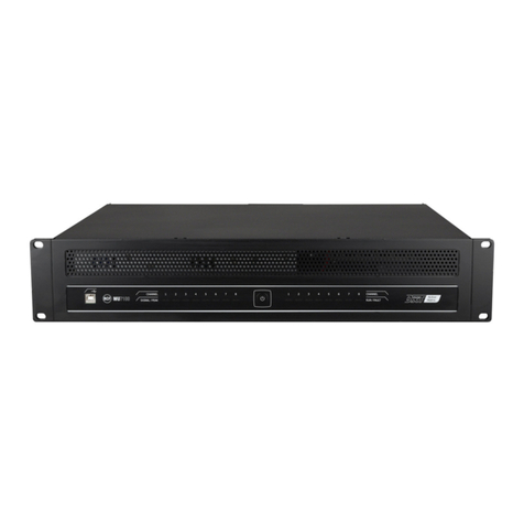
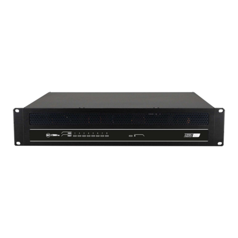
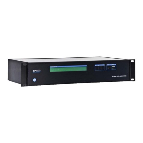
RCF DXT 3000 User manual

OWNER’S MANUAL
MANUALE UTENTE
DXT 3000
QUICKSTART GUIDE INTERLINK MODE
GUIDA PER ATTIVAZIONE IN MODALITÀ INTERLINK


3
CONTENTS
ENGLISH ...................................................................................................................................................... 4
ITALIANO ................................................................................................................................................... 22

4
ENGLISH
PRELIMINARY NOTES
This quickstart guide does not cover the standard o erations already ex lained in the DXT 3000 single unit
quickstart guide, as for exam le: the s are am lifier configuration, the activation modes for the emergency
messages and reset using the GPI section on the main board, the rocedure for connecting the batteries and
switching on the unit, the installation of the o tional MG 3006 board, etc.
It is an extension to the single unit quickstart guide that includes the rocedure for the start-u of multi le DXT
3000 units connected with the INTERLINK BUS.
IN ORDER TO EASE THE START-UP
•It is recommended to install the DXT 3000 units in order to allow easy access to the front anel and its
internal arts (indicatively kee 1.5 metres from the floor to the bottom side of the unit). The installation
of all DXT 3000 units in the same technical room makes easier and quicker the start-u of the system.
•The start-u rocedure requires sequential and re eated access to all the units. In case of distributed
installation of DXT 3000 units in multi le technical rooms, the final hase of the start-u rocedure is
quicker if the installer allows that all the rimary 230VAC su ly of all the DXT 3000 units are controlled
by a main ower switch located in the MASTER unit osition, that allows the simultaneous switch-on of
all the units.
•INTERLINK board is su orted by DXT 3000 system equi ed with firmware 4.1.0 and following releases.
All the interlinked DXT 3000 units need to be equi ed with the same firmware release.

5
1. EMERGENCY ACTIVATION MODES
With more DXT 3000 units connected in INTERLINK mode it is ossible to activate the emergency message in
multi le ways. As first thing it is necessary to choose one modality to activate the emergency message according
to the features of the installation.
1.1. LOCAL EMERGENCY ACTIVATION
The following modalities feature a simultaneous re roduction of the emergency messages from the different
DXT 3000 units connected to the system. They are referable when multi le DXT 3000 units cover areas that
are not acoustically isolated from each other.
MULTIPLE ACTIVATION COMMANDS
Every DXT 3000 unit is interfaced with Fire Alarm System (FAS) in an inde endent connection through its own
GPI board. In this way it is ossible to select individually the zones in which to activate the emergency message,
by roviding se arate activation commands for each zone. The re roduction of the emergency message will be
simultaneous between the different DXT 3000 units according to the simultaneity of the activation commands.

6
SINGLE ACTIVATION COMMAND
If the DXT 3000 units are installed in the same technical room (distance within 5 metres), it is ossible to extend
hysically the activation command from the MASTER unit main board to the SLAVE units main board using a
third CJ 428 CAT cable (in addition to the two CJ 428CAT cables for INTERLINK BUS).
1.2. GLOBAL EMERGENCY ACTIVATION
The following modalities of global emergency activation generate non-negligible latencies between the
emergency messages re roduced by the different DXT 3000 units. It is advisable to use the following modalities
only when all DXT 3000 units cover acoustically se arated s aces, so they do not interfere within each other.
ITL EVAC COMMAND ON IT 3010 BOARD (or IE 3008) on MASTER UNIT
The command ITL EVAC on IT 3010 board (or IE 3008) of the MASTER unit (the first of the INTERLINK CHAIN)
activates the emergency message in all the zones of all the DXT 3000 units connected to the system. The zones
belonging to different DXT 3000 units will have different latency in the re roduction of the emergency message.
BM 3804 / BM3804FM CONSOLE
Both console models BM 3804 and BM 3804FM can be used as emergency consoles. As with the standalone
DXT 3000 system, u to four consoles can be connected to the MASTER unit, but only the first one in the chain
(the one connected directly to the MASTER unit) can be used as emergency console. The second console and
the following ones need local ower su ly (RCF mod. ACAD2405).
The emergency console allows, if equi ed with ro er BE 3806 extensions (one BE 3806 for each DXT 3000
unit connected to the system), to select each zone where to activate the emergency message. However, zones
belonging to different DXT 3000 unit will feature a different latency in the re roduction of the message.

7
2. SETTINGS
The following settings must be made on the MASTER and SLAVE units with all the SYSTEM TURNED OFF,
without rimary 230VAC ower su ly and with batteries disconnected.
The settings are a combination of Jum ers (to be moved or to be installed) and Di Switches on different boards
inside the DXT 3000 units.
2.1. MAIN BOARD
Install 2 jum ers above the message board, as indicated in the following icture. (These 2 jum ers are not
resent in the single DXT 3000 unit, but they are included with the IE 3008 Board).
If console BM 3804 / BM 3804FM is used, set the di switch #1 (LOCAL BM 380X) to ON (right osition).

8
BM 380X UMPER
Set the Jum er BM 380X on the main board of each unit as described below:
•jum er set to LOCAL (left side) for the MASTER unit;
•jum er set to ITL (right) for all the SLAVE units.

9
BGM UMPER
Set the BGM Jum er BGM on the main board of all the units as described below:
•jum er set to LOCAL (Left) for the MASTER unit. In this way the MASTER unit selects as in ut of the BGM
Channel the connector BGM IN on the main board (recommended).
When the BGM jum er is set to ITL for the MASTER unit, it is enabled as in ut of the BGM channel the
BGM IN connector on the IE 3008 Board (or IT 3010 if resent). The connector BGM IN resent on the
main board in this case is disabled.
•for every SLAVE unit, set the JUMPER to LOCAL if you wish to use the BGM layer of the SLAVE unit itself;
set the JUMPER to ITL if you wish to use the same BGM channel coming from the MASTER unit.

10
2.2. IE 3008
DIP SWITCH MASTER/SLAVE ID
The di switches of all DXT 3000 units must be set as described in the table below. The osition ON (called “1”
in the table) corres onds to the di switch in the lowered osition, while the osition OFF corres onds to the
di switch in the lifted u osition.
Exam le in figure above:
ID 0 > ON.
ID 1 > OFF.
ID 2 > OFF.
MASTER/SLAVE > ON.

11
This is the DIP SWITCH configuration for the MASTER unit of a system with a total of 2 DXT 3000 units connected
on the INTERLINK BUS.
REDUNDANCY ENABLE
Setting the Jum er to ON the redundancy check on the INTERLINK bus is enabled. In case of redundancy fail
the error message *INTERLINK* will be dis layed on the front anel. Setting the Jum er to OFF the redundancy
check on the INTERLINK bus is disabled.

12
RL A - RL B
Two Jum ers must be installed on RL A and RL B on the IE 3008 boards belonging to the MASTER unit and the
LAST SLAVE U NIT of the INTERLINK chain. These two jum ers are included with the IE 3008 board, and by
default they are installed. Remove RL A and RL B jum ers only on the intermediate Slave units.
2.3. IT 3010
IT 3010 is an additional board for the DXT 3000 system that can be used exclusively together with the INTERLINK
board IE 3008. Its six transformers im rove the transmission of audio signals when the connection of the
INTERLINK BUS resent noise and disturbances. Res ect to IE 3008 it offers the ossibility to connect the DXT
3000 units with RJ 45 connectors, in addition to the screw terminals. For these reasons it is advised the
installation of one IT 3010 board for any DXT 3000 unit connected to the system, in articular when the length
of the INTERLINK BUS exceeds 10 metres.
NOTE: Once installed the IT 3010 board it is difficult to access to the settings of the IE 3008 board. Make sure
that the settings on IE 3008 have been com leted correctly before roceeding with the installation of IT 3010
board.

13
UMPER
These jum ers need to by ass the transformers: these Jum ers must not be a lied.
NOTE: Using IT 3010 board it is not ossible to install MG 3006 board in the way described in the roduct
manual.

14
3. INSTALLING THE INTERLINK BOARD
This o eration must be com leted on every DXT3000 unit connected to the interlink system.
1. Remove the metal late on the right side of the main board by removing the 4 screws. This is the s ace
for installing the IE 3008 (and IT 3010) boards.
2. Install the IE 3008 board:
If IT 3010 board is also going to be installed, for fixing the IE 3008 board it is necessary to use the 4
s acers included in the IT 3010 board box.
If IT 3010 is not going to be installed, use the same screws removed from the metal late.
3. Make the connections for the IE 3008 board as in the following ictures.
Connect the Flat Cable (included with IE 3008 board) between IE 3008 and the main board.
Move the 24 V connector (coming from the ower su ly board) from the main board to the 24V IN of
the IE 3008 board.
Use the red-black cable (included with IE 3008) to connect 24V OUT on IE 3008 to 24V IN on the main
board.
If IT 3010 board is included:
4. Remove all screw terminals from IE 3008 board
5. Install IT 3010 board locked above the IE 3008 board and fix it to the s acers with the 4 screws. Make
sure that the terminals between IE 3008 and IT 3010 are well ressed and do not resent false contact.

15

16
4. CABLING
Descri tion of the cabling to be made between DXT 3000 units connected in INTERLINK mode.
4.1. BUS INTERLINK
2 x CJ428CAT CABLES are needed for each connection between DXT 3000 units (redundant connection). The
INTERLINK Bus connections will be done on the IT 3010 boards of all DXT 3000 unit (IE 3008 if IT 3010 are not
installed).
It must not be com leted the “ring connection” from the last SLAVE unit to the MASTER unit. The MASTER unit
is always the first DXT 3000 unit of the INTERLINK Chain.
EXAMPLE WITH 2 DXT 3000 UNITS
•MASTER unit: only ITL OUT A/B.
•SLAVE unit: only ITL IN A/B.
EXAMPLE WITH 4 DXT 3000 UNITS
•MASTER unit: only ITL OUT A/B.
•Intermediate SLAVE unit: ITL IN A/B and ITL OUT A/B.
•Last SLAVE unit in chain: only ITL IN A/B.

17
4.2. IT 3010
For the connection of the INTERLINK Bus the cable CJ428 CAT is used, with the following in layout for the RJ
45 connector.
INTERLINK BUS IN/OUT CONNECTION
As reviously shown:
•MASTER unit: only ITL OUT A/B;
•intermediate SLAVE unit: ITL IN A/B and ITL OUT A/B;
•last SLAVE unit in chain: only ITL IN A/B.

18
OTHER COMMANDS (MASTER UNIT ONLY)
Those commands are not indis ensable, see aragra h.1.2 GLOBAL EMERGENCY ACTIVATION.
ITL BGM can be used to connect BGM signal in alternative to the BGM connector available on the main board
(see aragra h 2.1 BGM JUMPER) – only on the MASTER unit.
On the IT 3010 board of the MASTER Unit with commands ITL EVAC/ITL RESET it is ossible to activate and
reset globally the emergency message in all the DXT 3000 units connected to the system (see aragra h 1.2).
4.3. IE 3008
If IT 3010 is not installed the INTERLINK Bus must be connected to the IE 3008 board. The connections are the
same as reviously described for IT 3010 board. The only difference is in the use of the screw terminal instead
of the RJ 45 connectors. As reviously stated, it is recommended the use of IT 3010 board when INTERLINK
BUS length is greater than 10metres.
The corres ondence to match between the CJ 428 CAT twisted airs and the screw terminal on the IE 3008
board is re orted below.
PIN
(from Left
to Right)
1 2 3 4 5 6 7 8
CJ 428 CAT
Colour
White /
Orange Orange White /
Green Blue White /
Blue Green White /
Brown Brown

19
The same considerations done before for IT 3010 are valid also for IE 3008 board.
ITL BGM: can be used to connect BGM signal in alternative to the BGM connector available on the main board
(see aragra h 2.1 BGM JUMPER) – only on the MASTER Unit.
On the IT 3010 board of the MASTER Unit with commands ITL EVAC/ITL RESET it is ossible to activate and
reset globally the emergency message in all the DXT 3000 units connected to the system (see aragra h 1.2).

20
5. TURNING ON THE SYSTEM
Before turning on the units with rimary 230 VAC ower su ly make sure that the batteries are disconnected
on every DXT 3000 unit.
Start from the LAST SLAVE unit of the INTERLINK chain.
5.1. SLAVE UNIT CONFIGURATION
Proceed with the following instructions for all the SLAVE units.
•A ly all the settings related to the single unit configuration:
•AUDIO SETTINGS:
•zone volume, source assign, assign levels, etc.
•Select emergency message.
•S are am lifier configuration (if needed).
•SAVE CONFIG: wait for the system to reboot.
•Switch off rimary 230VAC su ly.
Note: in order to switch off the unit it is not sufficient to move to OFF the di switch #6 of the main
board, but it is necessary to switch off the rimary ower su ly.
NOTE: according to the characteristics of the installation (in articular for very long INTERLINK bus lenght) it
might be necessary to a ly level correction to the two shared audio buses, BM 3804 and BGM. You can a ly
these regulation from the front anel of each unit in the following menu:
•AUDIO SET / BM 3804 / INPUT LEVEL;
•AUDIO SET / BGM / INPUT LEVEL.
5.2. MASTER UNIT CONFIGURATION
Proceed with the following instructions for the MASTER unit.
•A ly all the settings related to the single unit configuration:
•AUDIO SETTINGS:
•zone volume, source assign, assign levels, etc.
•Select emergency message.
•S are am lifier (if resent).
•DISCOVERY CONSOLE. Before doing the discovery console make sure that all BM 380X consoles (if
resent) are owered from local su ly. Kee the consoles owered for the following hases.
Table of contents
Languages:
Other RCF Security System manuals
Popular Security System manuals by other brands

ADT
ADT Galaxy 8 user guide

TIP TEMPerature Products
TIP TEMPerature Products LATALM001 quick start guide

FBII
FBII XL-4 Installation and setup guide

GOVCOMM
GOVCOMM Owl GC-IMPO-FIZ23L Installation and user manual

Menvier Security
Menvier Security TS2500 Operator's manual

OnQ Technologies
OnQ Technologies HMS 1100 owner's manual