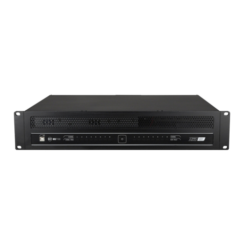
RCF IE 3008 User manual

USER MANUAL
MANUALE D’USO
IE 3008 DXT 3000 SYSTEM
INTERLINK BOARD
SCHEDA DI INTERCON-
NESSIONE PER SISTEMA
DXT 3000


TABLE OF CONTENTS
INDICE
ENGLISH
SAFETY PRECAUTIONS
INTRODUCTION
INSTALLATION AND INTERNAL LINKS
DESCRIPTION
FUNCTIONS
TECHNICAL SPECIFICATIONS
ITALIANO
AVVERTENZE PER LA SICUREZZA E PRECAUZIONI D’USO
INTRODUZIONE
INSTALLAZIONE E COLLEGAMENTI INTERNI
DESCRIZIONE
FUNZIONI
SPECIFICHE TECNICHE
4
5
5
8
9
10
12
13
13
16
17
18

4
ENGLISH
SAFETY PRECAUTIONS
IMPORTANT
IMPORTANT
This manual is an addendum to DXT 3000 user manuals. Refer to the MX
3250 and MX 3500 main units user manual for safety precautions and
system use.
Before installing IE 3008 interlink board, please read this instruction manual
carefully and keep it on hand for future reference, as it is to be considered a
part of the DXT 3000 system and must accompany it when it changes
ownership as a reference for correct installation. RCF S.p.A. will not assume
any responsibility for the incorrect installation and / or use.

ENGLISH
5
INTRODUCTION
INSTALLATION AND INTERNAL LINKS
IE 3008 is an additional board that extends system’s capability and
functionalities allowing the connection of several units (up to 8).
IE 3008 board shall be installed next to the main board, into the free slot on
its right side. Fix it through its four screws. Its dimensions are 130 mm x 115
mm. It is powered by the 24V DC available from the power supply. Move the
power cable from connector A to connector B.
A B

6
ENGLISH
Connect cables [1] and [2] (included) as shown in the figure above.
On the MASTER unit main board, move BM 380x jumper to from LOCAL to
ITL.
If a GLOBAL BGM is required in the system (same BGM from the MASTER to
all SLAVEs) move BGM jumper to from LOCAL to ITL.
Insert 2 jumpers in the connectors above the message board, as shown in
the picture.
The concurrent presence of IE 3008 and MG 3006 (MONITORED GPI
BOARD) is allowed. In that configuration MG 3006 will be placed over IE
3008, in the same slot, using suitable spacers.

ENGLISH
7
POWER SUPPLY
[1]
[2]
MAXIMUM NUMBER OF UNITS
IE 3008 allows connecting up to 8 units MX 3250 or MX 3500 (or a mix of
both models), in a MASTER/SLAVE configuration. The first unit will be the
MASTER, and the others will be SLAVEs. A fixed ID will identify each unit,
and can be set through a hardware DIP SWITCH placed on IE 3008.
MAXIMUM NUMBER OF CONSOLES BM 3804
IE 3008 allows connecting a maximum of 4 BM 3804, interlocked on a single
chain. Only the first one can be used as EMERGENCY console and it is
powered by the master unit. BM 3804 shall be connected to MAIN BOARD
of the master unit.
MAXIMUM NUMBER OF CONSOLE EXTENSIONS BE 3806
Up to 8 BE 3806 can be connected to each BM 3804 in the chain.
Each extension manages one MX unit, and buttons are statically assigned to
one zone only.
The maximum distance allowed between MX MASTER and last MX SLAVE is
800m.
The maximum distance allowed between MX MASTER and the last BM 3804
is 800m.
The maximum distance allowed between MX MASTER and the first BM 3804
with 8 BE 3806 connected (all powered by the MX unit) is 80m.

8
ENGLISH
DESCRIPTION
1 2
3
4
6 7
5
BUS A and BUS B INPUT CONNECTORS (8 poles): they receive 2 audio
channels (BGM and emergency console BM 3804) and commands from
the previous MX in the line. They are not used in the first MX
(MASTER).
BUS A and BUS B OUTPUT CONNECTORS (8 poles): they send audio
and commands to the next MX. They are not used in the last MX unit.
GLOBAL BGM INPUT CONNECTOR (3 poles): it is the input connector
for BGM audio signal, and shall be connected to first MX only
(MASTER), and the corresponding connectors on MX main board will
be disabled on all units. If local BGM only are required, use the
dedicated connector on the main board of each unit.
GLOBAL EVAC and RESET GPI: photo-coupled contacts to activate (and
reset) an EVAC event on the whole system. It can be triggered from
external Fire Alarm System (FAS).
1
2
3
4

ENGLISH
9
ID SET DIP-SWITCH: it allows to set the ID number of each unit, and to
set the MASTER.
5
BUS A and BUS B terminator resistors: insert the jumper on both pin to
terminate the lines and allow a correct monitoring. They shall be used
ONLY on the last SLAVE unit.
REDUNDANCY ENABLE: using the jumper is possible to deactivate the
BUS redundancy (set the jumper on OFF). In this way, the system will
not recognize and signal the absence of one BUS. Use this function
ONLY during installation and for test purpose. ALWAYS set it to ON
during normal system’s functioning.
6
7
LAST SLAVE IDMASTER
ID 0 ID 1 ID 2 MASTER /
SLAVE
SLAVE 01 1 0 0
SLAVE 02 0 1 0
SLAVE 03 1 1 0
SLAVE 04 0 0 1
SLAVE 05 1 0 1
SLAVE 06 0 1 1
SLAVE 07 1 1 1
1
0
0
0
0
0
0
0
FUNCTIONS
When several DXT 3000 units are connected using IE 3008 the following
funcionalities are available:
EVAC/ALERT/PAGING
BM 3804 allows to trigger EVAC/ALERT/PAGING events, at general level or
on each system zone. It means both the activation of pre-recorded or live
messages.
The activation of EVAC/ALERT/PAGING events from Fire Alarm System (FAS)
will act at local level on each unit. The same FAS can be connected to several
units.
LOCAL PAGING
Local paging for non-emergency purpose is possible connecting to each unit
a BM 3022 console.

10
ENGLISH
BGM
BGM works both at system or local level, depending on the specific setting
on the MX MASTER:
at system level, BGM will be injected on the dedicated input of IE 3008
on the MX MASTER. Global MUTE command is available on the main
board of the MX MASTER;
at local level, for each system, local sources can be connected to BGM
input on each main board. Local MUTE commands are available on
slaves MX main board.
-
-
24V DC
serial RS 485
2 (line)
2 (photo-coupled)
0 ÷ 40 °C (32 ÷ 104 °F)
removable screw terminals
4
CAT 6 FTP or J-type (RCF)
130 x 115 mm
150 g
Version 4.0.0. or later.
System can be updated by
SD Card starting from version 2.0.1.
Operating voltage:
Communication BUS A and B:
Number of audio channels:
General Purpose Inputs:
Ambient operating temperature:
Input connectors:
Max. number of daisy-chained BM 3804:
Paging microphone cable:
Dimensions:
Net weight:
Firmware requirement:
TECHNICAL SPECIFICATIONS µ
÷
±


12
ITALIANO
AVVERTENZE PER LA SICUREZZA E PRECAUZIONI D’USO
IMPORTANTE
IMPORTANTE
Questo manuale è aggiuntivo a quelli d’uso del sistema DXT 3000. Riferirsi
al manuale dell’unità centrale MX 3250 per quanto riguardo il
funzionamento del sistema e le precauzioni d’uso.
Prima di installare la scheda IE 3008, si prega di leggere attentamente le
istruzioni contenute in questo manuale, il quale è da conservare per
riferimenti futuri, costituisce parte integrante del sistema DXT 3000 e deve
accompagnare quest’ultimo anche nei passaggi di proprietà, per permettere
al nuovo proprietario di conoscere le modalità d’installazione.
L’installazione e l’utilizzo errati esimono la RCF S.p.A. da ogni responsabilità.

ITALIANO
13
INTRODUZIONE
INSTALLAZIONE E COLLEGAMENTI INTERNI
IE 3008 è una scheda opzionale che si installa all’interno delle unità centrale
MX 3250 e MX 3500 (sistema DXT 3000) e permette di collegare insieme
fino a 8 unità.
La scheda IE 3008 deve essere installata accanto alla scheda principale, nello
spazio libero sul lato destro. Fissare la scheda con le quattro viti già presenti
e le rondelle in dotazione. Le sue dimensioni sono di 130 mm x 115 mm.
L’alimentazione (24V DC) è resa disponibile dall'alimentatore: per il
collegamento spostare il cavo già presente dal connettore A al connettore B.
A B

14
ITALIANO
Collegare i cavi [1] e [2] in dotazione come mostrato nella figura qui sopra.
Sulla scheda principale dell’unità MASTER spostare il jumper BM 380x da
LOCAL a ITL.
Se è richiesta una musica di sottofondo globale (quindi la medesima per
l’unità MASTER e tutte le unità SLAVE), sulla scheda principale dell’unità
MASTER spostare il jumper BGM da LOCAL a ITL.
Inserire quindi 2 jumper nel connettore sopra la scheda messaggi, come
mostrato in figura.
La presenza contemporanea delle schede IE 3008 ed MG 3006 è ammessa.
In questo caso posizionare la scheda MG 3006 sopra IE 3008 utilizzando gli
appositi distanziali.

15
ITALIANO
ALIMENTATORE
[1]
[2]
NUMERO MASSIMO DI UNITÀ
IE 3008 permette di collegare fino ad 8 unità MX 3250 o MX 3500 (o una
combinazione di tali modelli) in configurazione MASTER/SLAVE. La prima
unità svolge la funzione di MASTER, mentre le altre sono unità SLAVE. Un ID
fisso identifica ciascuna unità, ed è settabile tramite apposito commutatore
posto sulla scheda IE 3008.
NUMERO MASSIMO DI CONSOLE BM 3804
IE 3008 permette di collegare fino a 4 console BM 3804, interbloccate su
una unica linea. Solo la prima console della linea ha le funzionalità di
EMERGENZA ed è alimentata dall’unità MX MASTER. Le console BM 3804
devono essere collegata alla MAIN BOARD dell’unità master.
NUMERO MASSIMO DI ESTENSIONI BE 3806
Fino ad 8 estensioni BE 3806 possono essere collegate a ciascuna BM 3804
della linea.
Ciascuna estensione gestisce una unità MX, ed i pulsanti sono staticamente
assegnati ad una e una sola zona.
La distanza massima consentita tra la MX MASTER e l’ultima MX SLAVE è
800m.
La distanza massima consentita tra la MX MASTER e l’ultima BM 3804 è
800m.
La distanza massima consentita tra la MX MASTER e la prima BM 3804 con
collegate 8 BE 3806 (tutte alimentate dall’unità MX) è 80m.

16
ITALIANO
DESCRIZIONE
1 2
3
4
6 7
5
Connettori di INGRESSO dei BUS A e BUS B (8 poli): ricevono 2 canali
audio (musica di sottofondo e console BM 3804) e comandi
provenienti dalla unità MX precedente nella linea. Non sono utilizzati
nella prima MX (MASTER).
Connettori di USCITA dei BUS A e BUS B (8 poli): inviano audio e
comandi alla unità MX successiva. Non utilizzati sull’ultima unità MX.
Connettore musica di sottofondo globale (3 poli): è il connettore di
ingresso del segnale audio musicale e deve essere collegato sulla
scheda IE 3008 dell’unità MX MASTER solo se si vuole una unica
musica di sottofondo per tutto il sistema. Se si vogliono solo musiche
locali, utilizzare il connettore sulla scheda principale di ciascuna unità.
ALLARME e RESET GLOBALI: contatti opto-isolati per attivare (e
resettare) un evento di ALLARME in tutto il sistema. Può essere attivato
dalla centrale di controllo e segnalazione esterna.
1
2
3
4

17
ITALIANO
Commutatore per indirizzo ID: permette di impostare il numero ID di
ciascuna unità.
Resistenze di terminazione dei BUS A e BUS B: inseire i jumper su
entrambi i pin per terminare le linee e permettere un corretto
monitoraggio. Devono essere utilizzate solo sull’ultima unità.
Abilitazione della ridondanza: inserendo il jumper in posizione OFF si
disabilita la ridondanza dei BUS. In questo modo il sistema non
riconosce nè segnala l’assenza di uno dei due BUS. Da utilizzare solo in
fase di installazione per test preliminari. Posizionare SEMPRE su ON il
jumper durante il normale funzionamento del sistema.
LAST SLAVE IDMASTER
ID 0 ID 1 ID 2 MASTER /
SLAVE
SLAVE 01 1 0 0
SLAVE 02 0 1 0
SLAVE 03 1 1 0
SLAVE 04 0 0 1
SLAVE 05 1 0 1
SLAVE 06 0 1 1
SLAVE 07 1 1 1
1
0
0
0
0
0
0
0
FUNZIONI
Quando più unità DXT 3000 sono collegate tramite scheda IE 3008 sono
disponibili le seguenti funzioni:
ALLARME/ALLERTA/ANNUNCI
Le console BM 3804 permettono di generare eventi di
ALLARME/ALLERTA/ANNUNCI a livello globale su ogni singola zona del
sistema, sia in termini di messaggi pre-registrati che di annunci live.
L’attivazione di eventi di ALLARME/ALLERTA/ANNUNCI dalla centrale di
controllo e segnalazione esterna agisce a livello locale su ciascuna unità. La
stessa centrale può essere collegata a più unità.
ANNUNCI LOCALI
A ciascuna unità può essere collegata una console BM 3022, da utilizzare
per annunci locali con finalità non di emergenza.
5
6
7

18
ITALIANO
MUSICA DI SOTTOFONDO
La musica di sottofondo può essere utilizzata sia a livello globale che a livello
locale, a seconda dell’impostazione sull’unità MX MASTER:
a livello globale il segnale musicale può essere iniettato dall’apposito
connettore su scheda IE 3008 dell’unità MX MASTER. Il comando di
MUTE globale è disponibile sulla scheda principale dell’unità MX
MASTER;
a livello locale, per ciascun sistema, la sorgente locale può essere
connessa all’apposito ingresso sulla scheda principale, così come il
comando di MUTE locale.
-
-
SPECIFICHE TECNICHE µ
÷
±
24V DC
seriale RS 485
2 (livello linea)
2 (opto-isolati)
0 ÷ 40 °C (32 ÷ 104 °F)
terminali a vite removibili
4
CAT 6 FTP o J-type (RCF)
130 x 115 mm
150 g
Versione 4.0.0. o successive.
Aggiornamento effettuabile tramite
SD Card a partire dalla versione 2.0.1.
Tensione di funzionamento:
BUS di comunicazione A e B:
Numero di canali audio:
General Purpose Inputs:
Temperatura di utilizzo:
Connettori di input:
Massimo numero di console microfoniche BM 3804:
Cavo console microfoniche:
Dimensioni:
Peso netto:
Requisiti firmware:

0068
RCF S.p.A. - Via Raffaello Sanzio 13, 42124 Reggio Emilia, ITALY
18
0068-CPR-007/2015
EN 54-16:2008
DXT 3000
Provided options (EN 54-16:2008)
DoP: 001_18
Other technical data: see operational manual.
Voice alarm control and indicating equipment for fire detection and fire
alarm systems for buildings
EN 54-4:1997 + A1:2002 + A2:2006
Power supply equipment for fire detection and fire alarm systems
for buildings
7.3
7.6.2
7.7.2
7.8
7.9
8.3
8.4
10
12
13.14
Audible warnings
Manual silencing of the voice alarm condition
Manual reset of the voice alarm condition
Output to fire alarm devices
Voice alarm condition output
Indication of faults related to the transmission path to the CIE
Indication of faults related to voice alarm zones
Voice alarm manual control
Emergency microphone(s)
Redundant power amplifiers

10307600 Rev B 2018 / 03
www.rcf.it
Salvo eventuali errori ed omissioni.
RCF S.p.A. si riserva il diritto di apportare modifiche senza preavviso.
Except possible errors and omissions.
RCF S.p.A. reserves the right to make modifications without prior notice.
RCF S.p.A.
Via Raffaello Sanzio, 13
42124 Reggio Emilia - Italy
Tel +39 0522 274 411
Fax +39 0522 232 428
e-mail: info@rcf.it
Table of contents
Languages:
Other RCF Security System manuals