FBII XL-4 Assembly instructions

N9144V1 10/98
;
;/
/
;
;/
/
%
%
;
;/
/
6HFXULW\6\VWHP
,QVWDOODWLRQDQG6HWXS*XLGH
9HUVLRQ

ii
Table of Contents
Conventions Used in This Manual.................................................................................................................. iv
Section 1 - Introduction...................................................................................................................................1–1
General...............................................................................................................................................................1–1
UL Listings........................................................................................................................................................1–2
How To Use This Manual .................................................................................................................................1–2
Related Documentation ....................................................................................................................................1–2
Section 2 - System Components.....................................................................................................................2–1
Control Panels...................................................................................................................................................2–1
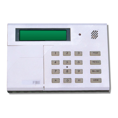
Keypads..............................................................................................................................................................2–1
Expansion Modules...........................................................................................................................................2–1
Accessories.........................................................................................................................................................2–1
Multiplex Peripherals.......................................................................................................................................2–2
Section 3 - System Wiring And Hookup.......................................................................................................3–1
Wiring Diagram.................................................................................................................................................3–2
Zone Hookup......................................................................................................................................................3–4
Hardwired Zone Expander (Optional) .............................................................................................................3–4
Multiplex Zone Expander .................................................................................................................................3–5
Keypad Connections..........................................................................................................................................3–6
Auxiliary Power.................................................................................................................................................3–8
Programmer Connection...................................................................................................................................3–8
JP1......................................................................................................................................................................3–8
JP2......................................................................................................................................................................3–9
Default Reset.....................................................................................................................................................3–9
Panel Reset........................................................................................................................................................3–9
Local Printer Connection..................................................................................................................................3–9
Line Seizure.......................................................................................................................................................3–9
Ground ...............................................................................................................................................................3–9
Telephone Line..................................................................................................................................................3–9
Tamper Switch ................................................................................................................................................3–10
Relay #1............................................................................................................................................................3–10
Relay #2 [Smoke Detector Power Reset]........................................................................................................3–11
Trigger Connector ...........................................................................................................................................3–12
Transformer.....................................................................................................................................................3–13
Battery Backup................................................................................................................................................3–13
Keypad Mounting............................................................................................................................................3–13
Section 4 - Multiplex Polling Loop................................................................................................................4–1
Multiplex Expander Installation......................................................................................................................4–1
Polling Loop Overview......................................................................................................................................4–2
Section 5 - System Operations........................................................................................................................5–1
Keypad Layout ..................................................................................................................................................5–1
Sample LCD Display.........................................................................................................................................5–4
Keypad Function Keys......................................................................................................................................5–4
Arming The System...........................................................................................................................................5–4
STAY..................................................................................................................................................................5–6
Auto Stay ...........................................................................................................................................................5–6
INSTANT...........................................................................................................................................................5–6
Instant-Stay.......................................................................................................................................................5–7
Bypass................................................................................................................................................................5–7
Forced Arming...................................................................................................................................................5–8
Unbypass............................................................................................................................................................5–8
Groups................................................................................................................................................................5–9
Group Bypass.....................................................................................................................................................5–9

Table of Contents (cont'd)
iii
Group Unbypass..............................................................................................................................................5–10
User Programming..........................................................................................................................................5–10
User Deletion...................................................................................................................................................5–11
Disarming ........................................................................................................................................................5–12
Keypad Auxiliary Conditions .........................................................................................................................5–12
Duress/Ambush ...............................................................................................................................................5–13
LCD Keypad Programming Mode..................................................................................................................5–13
Quick Commands ............................................................................................................................................5–13
Log Dump Function.........................................................................................................................................5–17
Keypad Function Summary............................................................................................................................5–18
Section 6 - Installer Functions.......................................................................................................................6–1
Keypad Programming.......................................................................................................................................6–1
Time Date Setup................................................................................................................................................6–1
Walk Test...........................................................................................................................................................6–2
Walk Test With Bell Output.............................................................................................................................6–3
Default Reset.....................................................................................................................................................6–3
System Log View...............................................................................................................................................6–3
Index......................................................................................................................................................................I-1

iv
Conventions Used in This Manual
Before you begin using this manual, it is important that you understand the meaning of the
following symbols (icons).
ULThese notes include specific information that must be followed if you are installing this system for
a UL Listed application.
These notes include information that you should be aware of before continuing with the
installation, and which, if not observed, could result in operational difficulties.
This symbol indicates a critical note that could seriously affect the operation of the system, or
could cause damage to the system. Please read each warning carefully. This symbol also
denotes warnings about physical harm to the user
.
ON: AWAY . . . . . . .
. . . Exit now . . . In the text of this manual, LCD Keypad messages are shown in a single-line box.

1–1
SECTION 1
Introduction
••••••••••••••••••••••••••••••••••••••••••••••••••
In This Section
♦General
♦UL Listings
♦How To Use This Manual
♦Related Documentation
••••••••••••••••••••••••••••••••••••••••••••••••••
General The XL-4 and XL-5 Series Control-Communicators are fully programmable devices with
remote communication and control capabilities. Each control contains 8 hardwired zones
located on the main control panel with multiplex and hardwired expansion capabilities. The
expansion options include:
•8 zone hardwire expansion (through 7105 module), providing a total of 16 hardwired zones,
or
•XL–4 Multiplex polling loop expansion (through 7120 module), providing two wire
multiplex loop of 64 zones (total system capacity of 72 zones)
•XL–5 Multiplex polling loop expansion (through 7126 module), providing two wire
multiplex loop of 120 zones (total system capacity of 128 zones)
The system can also be setup in a partitioned configuration. Partitioning allows the control
to look like as many as eight different protected locations to the Central Station. Each
partition will be assigned zones, users and keypads. The account numbers transmitted for
each partition are definable. Partitions can be setup to protect different functional areas of
the same location (example, office area vs. warehouse) or different premises within close
proximity (example, shopping center or multifamily complex).
UL
If a partitioned or double area installation is configured, UL requires that the following installation
requirements be observed.
1. All partitions or areas
must be
owned and managed by the same person(s).
2. All partitions or areas
must be
part of one building at one street address.
3. The audible alarm device(s)
must be
placed where it/they can be heard in all partitions or
areas.
4. The control cabinet itself
must be
tamper protected and connected to a 24-hour type zone so
that any unauthorized access to the control cabinet will cause an alarm.
The system also contains an event log that stores the past 128 events in time stamped order.
This event log can be viewed by the installer through a LCD keypad, retrieved remotely from
the PC Downloading software or automatically transmitted to a remote or local printer at a
specified time.
Programming of the control can be accomplished either through the LCD keypad locally, or
remotely from the Alarm Company location using the EZ-MATE PC Based Downloader. In
addition, remote operations can be performed.

Xl-4, XL-4B, and XL-5 Hookup and Installation Instructions Version 4
1–2
Failure to connect and program the control unit as described in this manual is a violation of the
Listing Mark. Programming requirements are contained in the LCD Keypad Programming Guide.
UL Listings The XL-4 is the Residential (Household) version of the has been listed by Underwriters
Laboratories for the following applications:
UL 1023 Household Burglar
UL 985 Household Fire Warning
The model XL-4B is the Commercial Burglary configuration of the control panel and has
been listed by Underwriters Laboratories for the following applications:
UL 365 Police Connected Burglar (Grade A Mercantile, Grade B)
UL 609 Local Burglar (Grade A Mercantile, Grade B)
UL 1610 Central Station Burglar (Grade B, Grade C)
UL 1635 Digital Burglar
How To Use This Manual
The Installation and Setup Guide has been organized into the following sections:
Section 1: Introduction – Describes the basic features and capabilities of the control and
explains the sections of the Installation Instructions.
Section 2: System Components – Specifies the components and accessories available with
the system.
Section 3: System Hookup And Wiring – Wiring diagram and installation instructions for
the control panel.
Section 4: Multiplex Polling Loop – Describes the functions of the multiplex polling loop.
Section 5. System Operations – Describes the operational procedures as performed through
the LCD and LED keypads.
Section 6. Installer Functions –Defines the keypad commands reserved for installers during
the installation and troubleshooting of the control panel.
Related Documentation
XL-4, XL-4B, and XL-5 LCD Keypad Programming Guide
Detailed manual describing the complete programming of a control through the LCD keypad.
This manual describes and explains all of the programmable parameters of the system.
User Guide
Booklet designed for the end user to describe how to use the system. This manual covers both
the LED and LCD keypads.

2–1
SECTION 2
System Components
••••••••••••••••••••••••••••••••••••••••••••••••••
In This Section
♦Control Panels
♦Keypads
♦Expansion Modules
♦Accessories
♦Multiplex Peripherals
••••••••••••••••••••••••••••••••••••••••••••••••••
Control Panels
XL-4 Includes 8 zone control/communicator and transformer. Household Burglary and
Fire version of the XL-4 system. Keypads available separately.
XL-4B XL-4 for UL Mercantile Applications. Contains control panel, transformer, and
attack proof enclosure suitable for UL commercial installations. Keypads available
separately.
XL-5LT 8 zone control/communicator, less transformer. Keypads available separately.
Keypads
XK-7LC
XK-5LC LCD Keypad, two line by sixteen-character English language display. Up to 8
LCD keypads can be used per system.
XK-716
XK-516 LED Keypad with separate zone indicator lights. Up to 8 LED keypads can be
used per system. Note: This keypad can only be used in systems with zone
numbers less than 16.
Expansion Modules
7105 Zone Expander. Plug in module provides an additional eight hardwired zones for
the XL-4 and XL-5.
7120 XL-4 Multiplex Expansion Module. Plug in module provides expansion capability
of 64 zones on two-wire polling loop bus.
7126 XL-5 Multiplex Expansion Module. Plug in module provides expansion capability
of 120 zones on two-wire polling loop bus.
7130 Serial Interface Module. Used to connect a serial printer (300-Baud) for the
purpose of outputting the system log to a local serial printer.
Accessories
7103UL Trigger cable assembly to interface to the controls voltage level trigger outputs.
7700 EZ-Mate PC Downloader. Software written for IBM or compatible personal
computers (requires a hard drive) and a Hayes 1200 Smartmodem or Hayes
Optima 33.6 External modem (configured as 2400) with a 7702 interface. Provides
database maintenance and remote communications with the control. Note: The
downloading software has not been investigated by Underwriters Laboratories
Inc.

Xl-4, XL-4B, and XL-5 Hookup and Installation Instructions Version 4
2–2
Multiplex Peripherals
XL-4701 Single Point Multiplex Interface.
XL-4702 2 Point Multiplex Adapter Module that allows two conventional alarm sensing
devices to be connected to the multiplex bus.
XL-4708 8 Point Multiplex Adapter Module. Used to interface 8 conventional sensing
devices to the multiplex bus. Each point will contain a unique address.
XL-4722 Dual Element Passive with built in multiplex point.
XL-4750SDT Smoke Detector with built in multiplex point.
ZR-745MSL Recessed Contact with RPM.
ZR-750MOH Multiplex Overhead Door Cantact.
ZR-795MR Recessed Multiplex Contact.
The controls multiplex capability will ONLY operate with Fire Burglary Instruments multiplex
accessories.
A ZR-700P Programmer Multiplex Contacts is needed to program the multiplex address for the
XL-4701, ZR-745MSL, ZR-750MOH, and ZR-795MR.
XL-4705 Relay Module. Each XL-4705 relay module contains 5 relays that may be used by
the system alarm types. Each relay has a unique address selected by Dip switch
settings within the XL-4705 Relay Module.

3–1
SECTION 3
System Wiring And Hookup
••••••••••••••••••••••••••••••••••••••••••••••••••
In This Section
♦Wiring Diagram
♦Zone Hookup
♦Hardwired Zone Expander
♦Multiplex Zone Expander
♦Keypad Connections
♦Auxiliary Power
♦Programmer Connector
♦JP1
♦JP2
♦Default Reset
♦Panel Reset
♦Ground Start
♦Line Seizure
♦Ground
♦Telephone Line
♦Tamper Switch
♦Relay #1
♦Relay #2
♦Trigger Connection
♦Transformer
♦Battery Backup
♦Keypad Mounting
••••••••••••••••••••••••••••••••••••••••••••••••••

Xl-4, XL-4B, and XL-5 Hookup and Installation Instructions Version 4
3–2
Wiring Diagram
1Z
1
3Z
2
5
6Z
4
7Z
5
8
9Z
6
10 Z
7
11
12 Z
8
13
14
15
16
2
4Z
3
1W
2.2k
1W
2.2k
1W
2.2k
1W
2.2k
KEYPADS
XK-7LC/XK-716
XK-5LC/XK-516
Max 280mA
(150 mA UL)
AUX POWER
(See #34, 35)
[–]
[+]
18 19 20 21 22 23 24 25 26 27 28 29
T R T R N/O N/CCOM *N/O N/CCOM
EARTH GROUND
(See note 1)
RJ31X CONN
Model 368
Cord
GREEN
RED
BROWN
GRAY
HOMETELCO
SMOKE POWER
or
ALARM PWR 2
(See note 4 &
detail A)
RELAY 2
ALARM PWR 1
BELL OUTPUT
(See note 2 & 3)
[–] [+]
RELAY 1
GND
*Cut for
dry
contact
on RLY1
JP2
37
36
35
34
33
32
31
30
TRANSFORMER
16.5 VAC 40VA
Model 1361
AUX POWER
12 – 12.8 VDC Reg.
470MA Incl. 16 & 17
(250 MA UL)
AUX POWER
12 – 12.8 VDC Reg.
150 MA Max.
(250 MA UL)
ALARM POWER
12 VDC Reg.
Max. 2 Amps
(1 Amp UL)
[+]
[–]
[+]
[–]
[+]
[–]
12V 5AH
BATTERY
Model 1250
RED (+)
BLACK (–)
INSTRUCTIONS
NOTE 1: Connect to cold water pipe
ground. 16 gauge at 15 feet.
NOTE 2: Terminal #27 is internally
connected to terminal #31. For dry
contact output on RELAY #1, cut jumper
JP2.
NOTE 3: Total alarm current for RELAY
1 & 2 is 2 Amps maximum (1 Amp UL)
NOTE 4:
a) RELAY # 2 can be used to RESET
SMOKE DETECTOR POWER (and fire
verification). If so, connect a jumper from
terminal 33 (+) to terminal 24. Smoke
detector power is derived from terminal
25 (+) and 26 (–). Also see detail A.
or
b) RELAY #2 can be used for a dry
contact in an alarm or trouble condition,
or for alarm power 2 by installing a
j
umper from terminal 31 (+) to terminal
24. Alarm power 2 will be derived from
terminal 23 (+) and 26 (–).
To reload factory default values remove
all power from the system (AC & DC)
then short TP1 to TP2. With short still
intact, reapply power (AC then DC), wait
10 seconds, and then remove short while
still powered.
To reset control panel, short TP2 to TP3.
For further information, consult the
Instruction Manuals.
17
RED
GREEN
YELLOW
BLACK

Section 3 – System Wiring and Hookup
3–3
XL-4 and XL-5
CONNECTIONS FOR HOUSEHOLD FIRE/BURGLAR ALARM SYSTEMS UL985 AND 1023
Detail A
NOTES: For UL Installation (Household)
1- Connect to a grounded could water pipe, 16 ga. at 15
feet.
2- Total AUX. Power available is 750 mA, which
includes keypad power and expansion boards when
using a 5AH battery.
3- System must be tested on a weekly basis. For
information refer to references (N9144 & N9146,
dated 7/92).
4- Do not connect the transformer to a receptacle
controlled by a switch.
5- Installation of equipment and wiring methods are
required to be in accordance with the National
Electricians code and ANSI/NFPA no 74. More
information may be obtained from the NFPA, Battery
March Park, Quincy, MA 02269.
6- Battery capacity for Emergency Standby is a
minimum of 4 hours. Under normal conditions this
battery will last 3 years, use only exact replacements.
7- Maximum entrance time is 45 seconds, maximum
exit time is 60 seconds.
8- Maximum of four keypads.
9- Expansion Modules: Model 7015 8 zone hardwire or
7120 (XL-4) /7126 (XL-5) Multiplex module.
10- Limited energy cable must be used.
SMOKE DETECTOR
CONTROL PANEL
MODEL ESL204A
E.O.L. RELAY
TO
ZONE
UL LISTED
SMOKE
DETECTOR
MODEL
ESL445AT
LISTED
HEAT
DETECTORS
Model EOL22 2.2K EOL Resistor
BROWN RED
BLACK
BROWN
[+] [–]
25 26
3214
WARNING
DISCONNECT PHONE LINES PRIOR TO
SERVICING.
WARNING
THIS UNIT INCLUDES AN ALARM VERIFICATION
FEATURE THAT WILL RESULT IN A DELAY OF THE
SYSTEM ALARM SIGNAL FROM THE INDICATED
CIRCUITS. THE TOTAL DELAY (CONTROL UNIT
PLUS SMOKE DETECTOR SHALL NOT EXCEED 60
S. NO OTHER INITIATING DEVICES SHALL BE
CONNECTED TO THESE CIRCUITS UNLESS
APPROVED BY THE LOCAL AUTHORITY HAVING
JURISDICTION. SMOKE DETECTOR
CIRCUIT CONTROL UNIT
(ZONE) DELAY - SEC. MODEL DELAY - SEC*
20
*Obtain from smoke detector installation instructions.
NOTE: For installations containing multiple smoke
detectors, break the wire to maintain supervision.
CAUTION:
Incorrect connections nay result in damage to the unit.
XL-4B
CONNECTIONS FOR HOUSEHOLD FIRE/BURGLAR ALARM SYSTEMS UL985 AND 1023
NOTES: For UL Installation (Household)
1- Connect to a grounded could water pipe, 16 ga. at 15
feet.
2- Total AUX. Power available is 750 mA, which
includes keypad power and expansion boards when
using a 5AH battery.
3- System must be tested on a weekly basis. For
information refer to references (N9144 & N9146,
dated 7/92).
4- Do not connect the transformer to a receptacle
controlled by a switch.
5- Installation of equipment and wiring methods are
required to be in accordance with the National
Electricians code and ANSI/NFPA no 74. More
information may be obtained from the NFPA, Battery
March Park, Quincy, MA 02269.
6- Battery capacity for Emergency Standby is a
minimum of 4 hours. Under normal conditions this
battery will last 3 years, use only exact replacements.
7- Maximum entrance time is 45 seconds, maximum
exit time is 60 seconds.
8- Maximum of four keypads.
9- Expansion Modules: Model 7015 8 zone hardwire, or
7120 Multiplex module.
10- Limited energy cable must be used.
WARNING
DISCONNECT PHONE LINES PRIOR TO
SERVICING.
WARNING
THIS UNIT INCLUDES AN ALARM VERIFICATION
FEATURE THAT WILL RESULT IN A DELAY OF THE
SYSTEM ALARM SIGNAL FROM THE INDICATED
CIRCUITS. THE TOTAL DELAY (CONTROL UNIT
PLUS SMOKE DETECTOR SHALL NOT EXCEED 60
S. NO OTHER INITIATING DEVICES SHALL BE
CONNECTED TO THESE CIRCUITS UNLESS
APPROVED BY THE LOCAL AUTHORITY HAVING
JURISDICTION. SMOKE DETECTOR
CIRCUIT CONTROL UNIT
(ZONE) DELAY - SEC. MODEL DELAY - SEC*
20
*Obtain from smoke detector installation instructions.
NOTE: For installations containing multiple smoke
detectors, break the wire to maintain supervision.
CAUTION:
Incorrect connections nay result in damage to the unit.
SMOKE DETECTOR
CONTROL PANEL
MODEL ESL204A
E.O.L. RELAY
TO
ZONE
UL LISTED
SMOKE
DETECTOR
MODEL
ESL445AT
LISTED
HEAT
DETECTORS
Model EOL22 2.2K EOL Resistor
BROWN RED
BLACK
BROWN
[+] [–]
25 26
3214
Detail A
UL Listed
MODEL MBL-8
MODEL AD10-12
Bell in listed Bell
Box, Model AB
Ademco
Connect with 16
AWG wire.
(Internal conn. - 4 to
6 and 3 to 5.)
NOTES: For UL Installation (MERCANTILE)
1- Installation of equipment and wiring methods shall be accomplished in
accordance with the National Electrical Code and ANSI/NFPA no. 70.
2- Fire Zones shall not be employed in a Commercial application.
3- Maximum entrance time is 15 seconds, maximum exit time is 60 seconds.
4- For UL certified installations, this product shall be connected to a
compatible listed Digital Alarm Receiver.
5- Installation requires circuit board enclosure tamper. Use either AMSECO
type ATS-1 or ADEMCO No. 19, closed circuit tamper switch. Mount
using the three holes provided on the side of the enclosure.
6- The cover of the enclosure must be secured with the eleven 1/2” long No.
8-32 screws provided.
7- Metal conduit shall be used to connect the bell to the control panel.
8- This control unit is intended for use as a Household Fire & Burglary
Warning System Control Unit, Grade A Local Alarm Unit, Grade A Police
Station Connected Unit with basic line security, and Grade B Central
Station Burglar Alarm Unit with compatible bell, or Grade C Central
Station Burglar Alarm Unit without compatible bell.
CONNECTIONS FOR MERCHANTILE BURGLAR ALARM SYSTEM UL 365, 609, AND 1635
(NOTE: All other connections are the same as above.) FOR ADDITIONAL INFORMATION REFER TO UL611 an UL681
201918 21 22 23 24 25 26 27 28 29
TO ZONE +
COLD WATER
PIPE GROUND
1 2
34
5 6
2.2K
TO ZONE
TO ZONE –
GROUND LUG
16 17
INSTALL JUMPER

Xl-4, XL-4B, and XL-5 Hookup and Installation Instructions Version 4
3–4
Zone Hookup
The first eight zones are connected to T1 through T12 on the main circuit board as follows:
Zone 1 Terminal 1 & 2 (-)
Zone 2 Terminal 3 & 2 (-)
Zone 3 Terminal 4 & 5 (-)
Zone 4 Terminal 6 & 5 (-)
Zone 5 Terminal 7 & 8 (-)
Zone 6 Terminal 9 & 8 (-)
Zone 7 Terminal 10 & 11 (-)
Zone 8 Terminal 12 & 11 (-)
Control panel zones on the main circuit board and through the zone expander should be
supervised using the 2.2K end of line resistors supplied.
Fire zones must use Listed part number EOL22 end of line resistors.
Hardwired Zone Expander (Optional)
The optional Zone Expander Module model 7105 provides an additional eight zones to the
control panel. Note: Either the 7105 expander, the 7120 expander (XL-4) , or the 7126
expander (XL-5) can be installed in the control panel. The 7105 zone expander can be
installed as follows:
1- Remove all power from the control panel.
2- Attach the three plastic support mounting pieces
to the zone expander module in the three holes
located on the printed circuit board.
3- Attach the zone expander to the control panel
board through the plug in connections located to the
left of the wiring diagram. Carefully align the six
pins on the top and bottom of the mounting
connectors. Press down firmly on the expander
board to insure that the board is secure in both
connectors.
Note: In order for the control panel to recognize the
zone expander the appropriate programming option
enabling the 8-zone expander must be turned on.
This can be accomplished through the LCD keypad
programming sequence or the EZ-Mate PC
Downloader. The second eight zones are connected
to T38 through T49 on the zone expander as follows:
Zone 9 Terminal 38 & 39
Zone 10 Terminal 39 & 40
Zone 11 Terminal 41 & 42
Zone 12 Terminal 42 & 43
Zone 13 Terminal 44 & 45
Zone 14 Terminal 45 & 46
Zone 15 Terminal 47 & 48
Zone 16 Terminal 48 & 49

Section 3 – System Wiring and Hookup
3–5
Multiplex Zone Expander
The 7120 or 7126 Multiplex expander module provides multiplex loop expansion to the
control panel. Each multiplex loop consists of a two-wire hookup that transmits power and
data from the control panel to the multiplex accessories. The multiplex expander can be
installed as follows:
1- Remove all power from the control panel.
2- Attach the three plastic support mounting pieces to the multiplex expander module in the
three holes located on the printed circuit board of the multiplex expander. Place the pointed
end through the bottom of the multiplex expander.
3- Attach the multiplex expander to the control panel through the plug in connections located
to the left of the wiring diagram. Carefully align the six pins on the top and bottom of the
mounting connectors. Press down firmly on the expander board to insure that the board is
secure in both connectors.
In order for the control panel recognize the multiplex expander the programming option enabling
multiplex operation must be turned on. This can be performed through the keypad programming
sequence or through the EZ-Mate PC Downloading software. Consult the appropriate manuals to
determine the method to enable the multiplex capability.
The multiplex bus can be connected as follows:
MULTIPLEX BUS LOOP
NUMBER/POLARITY 7120 MULTIPLEX
ZONE EXPANDER 7126 MULTIPLEX
ZONE EXPANDER
1 - LP1 - LP1 -
1 + LP1 + LP1 +
2 - N/A LP2 -
2 + N/A LP2 +
Proper polarity of the multiplex bus must be maintained.
-
LP1
+
-
LP2
+
7120
XL-4
XL-4B XL-5
7126
-
LP1
+
7120 SINGLE BUS 7126 DUAL BUS
EXPANDER FOR XL-4 AND XL-4B EXPANDER FOR XL-5

Xl-4, XL-4B, and XL-5 Hookup and Installation Instructions Version 4
3–6
Keypad Connections
The keypads are connected to the control panel with four-conductor cable to terminals 13
through 16. Attach each keypad used within the system to the terminals as follows:
T13 Red ( + voltage)
T14 Green
T15 Yellow
T16 Black ( - voltage)
The following rules apply concerning keypad wiring using 22 AWG wire:
A) Maximum keypad wire runs shall not exceed 1500 feet (any single keypad).
B) Daisy chain sum of keypad runs shall not exceed 3000 feet. This is the sum of the
distances to all keypads from the control panel on one daisy chain branch. For example, if
one keypad is 750 feet from the panel and another keypad is 500 feet from the first keypad,
then this distance would equal 750 + (750 + 500) = 2000 feet. Note that rule A still applies.
C) Total sum of all single runs and daisy chains shall not exceed 4000 feet. Note that rules A
& B still apply. For example, if there were two single keypad wire runs each 1000 feet from
the control panel, plus the daisy chain example from rule B, the sum of these wire runs
would equal 4000 feet.
D) If any keypads are powered from sources other than the control panel, then a common
ground must be connected between terminal 16 and the ground (negative) of the external
power supply.
E) Keypad wires should be run avoiding sources of possible AC induction or interference
caused by other devices. For example, Electrical wiring, Computer wires, etc.
The available keypad power (from terminals 13 and 16) is restricted to 280 mA (250 mA for
UL applications). Each keypad draws approximately 70 mA and therefore a maximum of 4
keypads can obtain power from these connections. Additional keypads must obtain their
power from the other auxiliary panel outputs (if sufficient capacity is available) or an
external power supply.
All keypads must be connected to terminals 14 and 15 regardless of where they obtain power.
Keypad Addressing
Both versions of keypads (LED models XK-716 or XK-516 and LCD models XK-7LC or XK-
5LC) contain switches to set the address of the keypad. This address will identify the keypad
number to the control panel. In a partitioned system each keypad can be assigned to a
partition.
Within the control panel programming questions the LED keypads are known as keypads 1-8
and the LCD keypads are known as 9-16.
These switches are located under the cover at the bottom left of XK-516 and XK-5LC
keypads. To access the switches in the XK5LC and XK-516 keypads, remove the front of the
keypad from the keypad back by placing a straight-slot screwdriver into one of the two slots
in the bottom of the keypad and twisting the screwdriver. The switches are located behind
the pull open door and zone card for XK-716 and XK-7LC keypads. The switch positions for
the keypads are as as shown below:

Section 3 – System Wiring and Hookup
3–7
The first three switches (SW1 - SW3) should be set as follows:
KEYPAD NUMBER
LCD SW1 SW3
1 9 ONONON
2 10 OFF ON ON
311ONOFFON
412OFFOFFON
5 13 ONONOFF
6 14 OFF ON OFF
715ONOFFOFF
8 16 OFF OFF OFF
On XK-716 and XK-7LC keypads, when the right hand side of the switch is pushed in the
switch is in the ON position. When the left-hand side of the switch is pushed in the switch is
in the OFF position. On XK-516 and XK-5LC keypads, when the switch is pushed toward the
back of the keypad the switch is in the ON position. When the switch is pushed toward the
front of the keypad the switch is in the OFF position.
The system should always be powered down and when changing dip switches or hooking up
keypads.
OFF
1 2 3 4
1234
ON
XK-5LC AND XK-516 BOTTOM VIEW (WITH BACK REMOVED)
XK-7LC AND XK-716 FRONT VIEW (WITH COVER OPEN)

Xl-4, XL-4B, and XL-5 Hookup and Installation Instructions Version 4
3–8
The factory default settings enable the first LCD keypad within the system (address 9, SW1-ON,
SW2-ON, SW3-ON). At least one LCD keypad is necessary in order to perform keypad
programming.
1. Keypads of the same type should not be set with the identical addresses.
2. The keypads need to be enabled within the programming sequence.
3. The control panel supports up to sixteen keypads consisting of eight LED and eight LCD
keypads.
4. LED keypads can only be utilized on systems with zone numbers less than 16 zones.
Switch 4 - Keypad Sounder
Enables or disables the keypad sounder. In the OFF position the keypad sounder will be
active. In the ON position the keypad will only sound indicating the depression of keys.
ULFor UL applications the keypad sounder MUST be enabled.
This switch is only read upon exit from the keypad programming sequence. Therefore to change
the keypad sounder status set the switch (SW4) to the desired position then enter and exit from
the keypad programming mode.
Auxiliary Power
Auxiliary power (13.8VDC regulated) can be obtained from three different outputs of the
control panel. The total regulated output power from the control panel is 900 mA (600mA for
UL applications) with the following current distribution:
TERMINALS MAX. CURRENT APPLICATION
13 (+) & 16(-) 280mA (250mA UL) Keypads
17 (+) & 16(-) 470mA (250mA UL) Misc. (Passives etc.).
Or 35 (+) & 34 (-)
33 (+) & 32(-) 150mA (100mA UL) Smoke Detectors
Note: Terminal 35(+) is internally connected to 17 (+). The maximum current available from
both of these points added together is 470mA (250mA for UL applications).
Power can be obtained from any of these connections provided that the total does not exceed
the rated capacity of the terminals.
Consult the specifications for the devices being connected to determine the power
requirements for your installation.
Programmer Connection
The section of the PC board labeled EZ-MATE Programmer is not used on the control panel.
Do not attempt to make any connections.
JP1 Adding a jumper to JP1 causes earth ground to become the system ground. Alternately, this
can be performed by connecting terminal 34 to 18.

Section 3 – System Wiring and Hookup
3–9
JP2 Jumper 2 is used in conjunction with the application of relay #1. JP2 should be cut if relay #1
is being used with dry contacts, or left connected if relay #1 is being used as a bell output.
Default Reset
Shorting TP1 to TP2 will cause the panel to revert to the original panel default values. This
should only be performed if the programming status is unknown and the panel defaults are
desired. The control panel default values can be viewed in the LCD Keypad Programming
Guide.
To perform a default reset, remove all power to the panel, AC & DC. Short TP1 & TP2 and
while short is still intact reapply power AC then DC. Wait 8 to 10 seconds then remove the
short while the unit is still powered. The system default reset may take 20 to 30 seconds.
If the INSTALLER LOCKOUT option has been selected within the programming sequence then a
default reset through these pins will perform a default with the exception of the CSID and Installer
Code.
Panel Reset Shorting connection TP3 to TP2 while the system is powered on will cause a panel reset to
occur. This will not alter any of the programming information within the system.
Local Printer Connection
This pin (P1) is used to connect to the 7130 Serial Printer Interface Module to output the
System Log to a local printer.
NOTE: P1 may be labeled as GND START on the PC board.
Line SeizureThis pin (P2) is active (low) when line seizure has occurred.
Ground Connect terminal to a cold water grounding pipe utilizing #16AWG wire at a distance no
greater than 15 feet. If the premises pipes terminate in PVC, this terminal must be
connected to a 6-foot grounding rod.
To increase lightning and static protection on this panel, we strongly recommend the use of the
Ground Lug
as instructed above instead of using terminal 18. The Ground Lug is located on the
lower left-hand corner of the panel
.
Telephone Line
Connect an FBII model 368 cord to an RJ31X jack as follows:
19 Green Telco Tip
20 Red Telco Ring
21 Brown Home Tip
22 Grey Home Ring
The FCC registration number is (AE398E-69554 AL-E) and the ringer equivalent is (0.0B).
The control panel should not be connected to party lines or coin operated phone lines. The
device should not be connected to a telephone line that has call waiting, unless the call
waiting interrupt numbers have been programmed into the panel dialing sequence.

Xl-4, XL-4B, and XL-5 Hookup and Installation Instructions Version 4
3–10
If this control panel will be used for uploading, downloading or remote command applications, the
telephone line connected to the control panel must not be shared with a fax machine or modem
.
Tamper Switch
For UL Mercantile installations the circuit board enclosure (panel model XL-4B) MUST be
tampered. Three mounting holes are provided on the right hand side of the enclosure to
install the tamper switch. (AMSECO ATS-1, or ADEMCO No.19) Refer to UL Standard 681
for further information.
Relay #1 Relay #1 can be used as a bell output or as dry contacts as shown below:
Bell Output
UL commercial installations require ADEMCO model AD10-12 or ADEMCO MBL-8 mounted
in the model AB bell housing. Maximum alarm load is 1 Amp.
REFER TO WIRING DIAGRAMS FOR FURTHER DETAILS
Connections To FBII Siren Drivers
Control 679 VS279 VS299
Panel Siren Driver Voice Siren Driver Voice Siren Driver
28 (Bell) 1 1 2
30(-) 2 3 7
31 (Const. Power) N/A 4 6
NOTES FOR VS279 & VS299
Burglary message requires Relay 1 programmed for latched operation. Fire message
requires relay 1 programmed for pulsed operation.
Consult the Installation Instructions of the siren drivers for additional information.
Dry Contacts
Contacts rated 110 VAC, 24 VDC, 3 Amps.
28
26
12 v
BELL
SET UP AS BELL OUTPUT JP2 CONNECTED
27
29
28
SET UP AS DRY CONTACTS JP2 CUT
NORMALLY OPEN
COMMON
NORMALLY CLOSED

Section 3 – System Wiring and Hookup
3–11
Relay #2 [Smoke Detector Power Reset]
Relay #2 can be used as a smoke detector reset or as dry contacts as shown below:
Smoke Detector
To utilize relay #2 as smoke detector power reset connect a jumper between terminals 33 and 24
to power the smoke detectors.
UL Listed smoke detectors: ESL model 445AT
This hookup applies to the connection of smoke detectors to the hardwired zones of the
control panel.
Smoke detector power ranges from 10.2 and 14.0 volts. The maximum voltage available for
smoke detectors is 100mA from terminals 32 and 33. Additional power is available through the
other aux. power outputs providing that the total power being used does not exceed the rated
values of the outputs and that the total power consumed does not exceed the standby
requirements. Consult the aux. power section for further information.
The unit has been designed to operate with four wire smoke detectors and end of line relays
for supervision of the power to the detectors. Listed below are some recommended smoke
detectors and EOL relays:
Gentex Model #6040 & 6041
Voltage 10 - 16 VDC, standby 5mA, Alarm 60mA
ESL Model # 445AT
Voltage 5.1 - 16.5VDC, standby 1.5mA, Alarm 100mA
Power supervision End of Line relay Model 204A
Standby 40mA at 12VDC
BRK System Sensor Model # 2412 or 2412TH
Voltage 11.3 - 17.3, standby 120mA, Alarm 77mA
End of line relay model # A77-716-01
Standby 25mA at 12VDC
SMOKE DETECTOR
CONTROL PANEL
MODEL ESL204A
E.O.L. RELAY
TO
ZONE
UL LISTED
SMOKE
DETECTOR
MODEL
ESL445AT
LISTED
HEAT
DETECTORS
Model EOL22 2.2K EOL Resistor
BROWN RED
BLACK
BROWN
[+] [–]
25 26
3214
WARNING
THIS UNIT INCLUDES AN ALARM VERIFICATION
FEATURE THAT WILL RESULT IN A DELAY OF THE
SYSTEM ALARM SIGNAL FROM THE INDICATED
CIRCUITS. THE TOTAL DELAY (CONTROL UNIT
PLUS SMOKE DETECTOR SHALL NOT EXCEED 60
S. NO OTHER INITIATING DEVICES SHALL BE
CONNECTED TO THESE CIRCUITS UNLESS
APPROVED BY THE LOCAL AUTHORITY HAVING
JURISDICTION. SMOKE DETECTOR
CIRCUIT CONTROL UNIT
(ZONE) DELAY - SEC. MODEL DELAY - SEC*
20
*Obtain from smoke detector installation instructions.
NOTE: For installations containing multiple smoke
detectors, break the wire to maintain supervision.
CAUTION:
Incorrect connections nay result in damage to the unit.

Xl-4, XL-4B, and XL-5 Hookup and Installation Instructions Version 4
3–12
Dry Contacts
Contacts rated 110 VAC, 24 VDC, 3 Amps.
Trigger Connector
The control panel contains eight voltage level triggers that are provided through connector
P3. The connections for the trigger outputs are displayed below and requires connection of
FBII part number 7103UL Trigger Connector. The triggers can be programmed for pulsed or
latched operation through the programming questions. The triggers when active deliver
12VDC, 25ma maximum.
Pin 3 of the trigger connector is an Arm/Disarm trigger which can be selected for high or low
output through the programming questions and is normally active high (high = 3mA, low =
12mA).
Trigger 7 is the data line and Trigger 8 is the clock line for the XL-4705 relay module, when
activated.
COLOR CONNECTION
White w/Yellow stripe Trigger 7
White w/Orange stripe Trigger 8
White w/Red stripe Trigger 6
White w/Brown stripe Arming Status
White w/Black stripe Trigger 5
Grey Trigger 4
Blue Trigger 3
Yellow Trigger 2
Orange Ground
Red Trigger 1
Brown Ground
Yellow Wire
Brown Wire
TR7
TR6
TR5
TR4
TR3
TR2
TR1
TR8
ARM
GND
GND
27
29
28
SET UP AS DRY CONTACTS. NO FIRE ON SYSTEM.
NORMALLY OPEN
COMMON
NORMALLY CLOSED
Other manuals for XL-4
3
This manual suits for next models
2
Table of contents
Other FBII Security System manuals

FBII
FBII XL-2 User manual

FBII
FBII XL-21 User manual

FBII
FBII XL-4B User manual

FBII
FBII XL-2T Assembly instructions

FBII
FBII XL-2S Silver User manual

FBII
FBII XL-2 User manual

FBII
FBII XL-2T Assembly instructions

FBII
FBII XL-2T Assembly instructions

FBII
FBII XL-1218R User manual

FBII
FBII OMNI-600EU User manual
Popular Security System manuals by other brands

Wearable Health Solutions
Wearable Health Solutions iHelp+ 3G Series owner's manual

E2S
E2S D1xS2FDC024-S instruction manual

Defender Security
Defender Security 812BF Operation guide

Mier products
Mier products Drive-Alert DA-073 instructions

Eldes
Eldes PITBULL ALARM PRO quick guide

CellGate
CellGate WATCHMAN EVO WP450 Series Quick install guide