RCF PL 82EN User manual

USER MANUAL
MANUALE D’USO
PL 82EN FLUSH-MOUNT
TWO-WAY CEILING
LOUDSPEAKER IN
COMPLIANCE WITH EN
54-24 STANDARD
DIFFUSORE ACUSTICO
A DUE VIE PER
CONTROSOFFITTO
CONFORME ALLA
NORMA EN 54-24

4
ENGLISH
SAFETY AND OPERATING
PRECAUTIONS
IMPORTANT NOTES
IMPORTANT NOTES
Before connecting and using this product, please read this instruction manual
carefully and keep it on hand for future reference. This manual is to be
considered an integral part of this product and must accompany it when it
changes ownership as a reference for correct installation and use as well as
for the safety precautions.
RCF S.p.A. will not assume any responsibility for the incorrect installation
and / or use of this product.
SAFETY AND OPERATING PRECAUTIONS
1. All the precautions, in particular the safety ones, must be read with special
attention, as they provide important information.
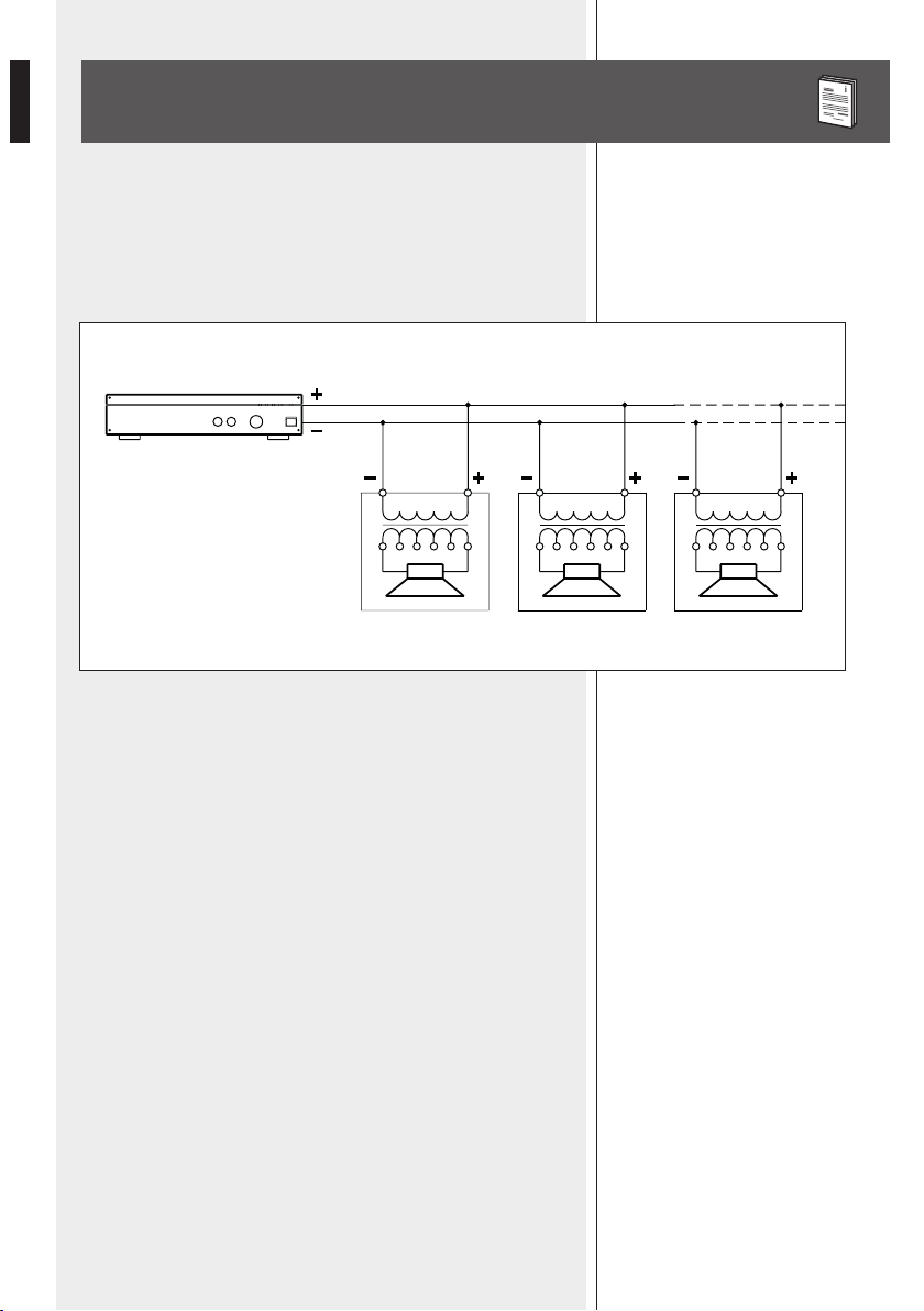
2. Loudspeaker lines (amplier outputs) can have a sufciently high voltage
(i.e. 100-70 V) to involve a risk of electrocution: never install or connect this
loudspeaker when the line is alive.
3. Make sure all connections have been made correctly and the loudspeaker
input voltage is suitable for the amplier output.
4. Protect loudspeaker lines from damage. Make sure they are positioned in a
way that they cannot be stepped on or crushed by objects.
5. Make sure that no objects or liquids can get into this product, as this may
cause a short circuit.
6. Never attempt to carry out any operations, modications or repairs that
are not expressly described in this manual.
Contact your authorized service centre or qualied personnel should any of
the following occur:
-The loudspeaker does not function (or works in an anomalous way).
-The cable has been damaged.
-Objects or liquids have got into the unit.
-The loudspeaker has been damaged due to heavy impacts or re.
7. Should the loudspeaker emit any strange odours or smoke, remove it from
the line after having immediately switched the amplier off.
8. Do not connect this product to any equipment or accessories not foreseen.
For suspended installation, only use the dedicated anchoring points and do
not try to hang this loudspeaker by using elements that are unsuitable or not
specic for this purpose.
Also check the suitability of the support surface to which the product
is anchored (wall, ceiling, structure, etc.) and the components used for
attachment (screw anchors, screws, brackets not supplied by RCF etc.),
which must guarantee the security of the system / installation over time, also
considering, for example, the mechanical vibrations normally generated by
transducers.

5
ENGLISH
9. RCF S.p.A. strongly recommends this product is only installed by
professional qualied installers (or specialised rms) who can ensure a
correct installation and certify it according to the regulations in force.
The entire audio system must comply with the current standards and
regulations regarding electrical systems.
10. Mechanical and electrical factors need to be considered when installing
a professional audio system (in addition to those which are strictly acoustic,
such as sound pressure, angles of coverage, frequency response, etc.).
11. Hearing loss
Exposure to high sound levels can cause permanent hearing loss. The acoustic
pressure level that leads to hearing loss is different from person to person
and depends on the duration of exposure.
To prevent potentially dangerous exposure to high levels of acoustic pressure,
anyone who is exposed to these levels should use adequate protection
devices.
When a transducer capable of producing high sound levels is being used, it is
necessary to wear ear plugs or protective earphones.
See the technical specications in the instruction manual for the maximum
sound pressure the loudspeaker is capable of producing.
12. To ensure a correct sound reproduction, loudspeaker phase is to be
respected (loudspeakers are connected respecting the amplier polarity).
This is important when loudspeakers are installed adjacent one another, for
instance, in the same room.
13. To prevent inductive effects from causing hum, noise and a bad system
working, loudspeaker lines should not be laid together with other electric
cables (mains), microphone or line level signal cables connected to amplier
inputs.
14. The loudspeaker cable shall have wires with a suitable section (twisted,
if possible, to reduce inductive effects due to surrounding electro-magnetic
elds) and a sufcient electrical insulation. Refer to local regulations since
there may be additional requirements about cable characteristics.
15. Install this loudspeaker far from any heat source.
16. Do not use solvents, alcohol, benzene or other volatile substances for
cleaning the external parts of this product. Use a dry cloth.

6
ENGLISH
RCF S.P.A.THANKS YOU FOR PURCHASING THIS PRODUCT, WHICH
HAS BEEN DESIGNED TO GUARANTEE RELIABILITY AND HIGH
PERFORMANCE.
The PL 82EN two-way ceiling loudspeaker is in compliance with EN 54-24
standard. It is equipped with a steel re dome and can be installed ush-mounted
in false ceilings or panels.
It is particularly suitable for reproducing alarm messages, as it provides particularly
intelligible voice reproduction and it is resistant to the high temperatures that can
be reached during a re.
Main features:
-High quality voice reproduction.
-8” coaxial loudspeaker.
-Transformer for connection to 100 V (/ 70V) constant voltage lines.
-Possibility to select the output power among several values.
-Steel construction with protection grille.
-Steel re dome with an attachment system that ensures quick installation.
-Ceramic terminal strip for connection (with earth contact).
-Quick system to x the loudspeaker to the re dome through two springs.
-Fire protection internal cables.
-Thermal fuse that prevents damage to the audio line due to heat on the speaker.
WARNING: MAke suRe thAt the loudspeAkeR Is INstAlled IN AstAble ANd secuRe WAy IN
oRdeR to AvoId ANy coNdItIoNs thAt MAy be dANGeRous foR peRsoNs oR stRuctuRes.
eNsuRe the suppoRt suRfAce (e.G. WAll, etc.) hAs the NecessARy MechANIcAl chARActeRIstIcs to
suppoRt the WeIGht of the loudspeAkeR. befoRe INstAllING the loudspeAkeR, cARefully check All
coMpoNeNts to be used ANd MAke suRe theRe Is No dAMAGe, defoRMAtIoN, coRRosIoN ANd/oR
MIssING oR dAMAGed pARts thAt could Reduce the sAfety of the INstAllAtIoN.
INoutdooR use,AvoId INstAllING the loudspeAkeR IN plAces exposed to hARsh WeAtheR coNdItIoNs.
the pl 82eN Is desIGNed foR flush-MouNt INstAllAtIoN IN fAlse ceIlINGs.
befoRe INstAllING the loudspeAkeR, MAke suRe theRe Is suffIcIeNt spAce behINd the fAlse ceIlING
pANel to hold the speAkeR: WIth Respect to the suppoRt suRfAce of the fRoNt flANGe of the
loudspeAkeR, AfRee spAce 150 MM (c. 6”) deep Is NecessARy.
DESCRIPTION
INSTALLATION

7
ENGLISH
FIGURE 1
FIGURE 2
FIGURE 3
1. Drill a hole of diameter 240 mm
(9.45”) in the false ceiling panel, as
shown in gure 1.
2. Loosen the two wing bolts A
(gure 2) that secure the two
attachment plates Band move the
plates upwards, then secure the two
plates Bby re-tightening the two wing
bolts A.
3. Insert the re dome in the hole
previously drilled (as shown in gure 1).
4. Loosen the two wing bolts A
again and move the two attachment
plates Bdownwards to secure
the re dome to the false ceiling
(as shown in gure 3).When this
operation is completed, re-tighten
the two wing bolts A.
ø 240 mm (9.45’’)
A A
B B

8
ENGLISH
FIGURE 4
5. Hang the speaker into the re
dome, tting the ends of one of the
two support springs Con the speaker
into one of the hooks D on the re
dome (as shown in gure 4).
6. Make the electrical connection as
described in the next manual section.
7. Fit the ends of the other support
spring Cto the second hook Don the
re dome.
8. Push the speaker into the re dome
until the front ange lays against the
false ceiling.
CONNECTION
WARNING: loudspeAkeR coNNectIoNs should be oNly MAde by quAlIfIed ANd expeRIeNced
peRsoNNel hAvING the techNIcAl kNoW-hoW oR suffIcIeNt specIfIc INstRuctIoNs to eNsuRe thAt
coNNectIoNs ARe MAde coRRectly ANd to pReveNt ANy electRIcAl dANGeR.
topReveNt ANy RIsk of electRIc shock, do Not coNNect loudspeAkeRs WheN the AMplIfIeR Is
sWItched oN. befoRe tuRNING the systeM oN, check All coNNectIoNs ANd MAke suRe theRe
ARe No AccIdeNtAl shoRt cIRcuIts.the eNtIRe souNd systeM shAll be desIGNed ANd INstAlled IN
coMplIANce WIth the cuRReNt locAl lAWs ANd ReGulAtIoNs ReGARdING electRIcAl systeMs.
D
C
D
C

9
ENGLISH
CERAMIC TERMINAL STRIP CONNECTION
TRANSFORMER POWER SELECTION
The connection to the 100 V (/ 70 V) constant voltage line is made through the
ceramic terminal strip, which includes a contact for earthing.
Insert the cable through one of the two rubber cable guides of the re dome.
Connect the positive wire to the speaker input IN 100 V (+) and the negative
wire to IN 0 (–).
Connect the earth wire (yellow-green) to the respective terminal strip contact.
Link the ‘TAP’ connector (red wire) to the transformer
contact having the desired power value
(see the next table and the gure 6).
TAP
(pins)
POWER
(100 V)
POWER
(70 V)
1 5 W 2.5 W
2 10 W 5 W
3 20 W 10 W
FIGURE 6
FIGURE 5
CERAMIC SCREW
TERMINAL
100 V RED
GREEN
0BLACK
COM
20 W
10 W 8 Ω
5 W
IN FUSE
TAP
1 2 3

10
ENGLISH
NOTES ABOUT CONSTANT VOLTAGE SYSTEMS
-The loudspeaker input voltage (Vd) shall correspond to the amplier output
voltage (Va).
-The sum of nominal power values (Pd x n) of all loudspeakers connected to the
line shall not exceed the amplier power (Pa).
-Make sure all loudspeakers are connected in phase to ensure a correct sound
reproduction.
-Always use cables having wires with an adequate cross-section, considering the
cable length and the total loudspeaker power.
-Loudspeaker lines must be kept separated from mains cable, microphone cables
or others, in order to avoid inductive phenomena may cause hum or noises.
-Use loudspeaker cables having twisted wires to reduce hum caused by inductive
effects due to coupling with electromagnetic elds.
AMPLIFIER
Pa = Amplier power
Pd = Speaker power
n = Number of speakers
Vd = Speaker input voltage
Va = Amplier output voltage
Pa > Pd x n Va
FIGURE 7

11
(1) Minimum value in between the two measured impedance peaks.
(2) Measures made with speaker mounted on a baffle and measurement microphone on the same axis (angle 0°).
ø272
ø236 mm
145
120
ENGLISH
SPECIFICATIONS
Input voltage:
Power (selectable) at 100V:
Input impedance (1):
Frequency response:
Sensitivity:
Max. sound pressure level:
Transducer:
Applicable wire section:
Body and grille material:
Body and grille colour:
Fire dome material:
Fire dome colour:
100 V ( / 70 V)
20 W – 10 W – 5 W (power values are halved at 70 V)
500 Ω – 1 kΩ – 2 kΩ
130 Hz ÷ 20 kHz (–10 dB)
94 dB (1 W, 1 m), 82 dB (1 W, 4 m)
106 dB (20 W, 1 m), 94 dB (20 W, 4 m)
8” coaxial
0.8 ÷ 4 mm²
steel
white
steel
red
Connector:
False ceiling cutout size:
Net weight:
Operating temperature:
Dimensions:
ceramic terminal strip
ø 240 mm (9.45”)
3.7 kg (7.65 lbs)
–30 ÷ +60 °C (–22 ÷ +140 °F)
ø 272 mm (10.71”), h: 145 mm (5.71”)
IP protection grade: IP 40
Coverage angle (-6dB) (2): 180° (500 Hz), 170° (1 kHz), 100° (2 kHz), 60° (4 kHz)

10307568 revB2017/ 06
www.rcf.it
RCF S.p.A. Italy
Via Raffaello Sanzio, 13
42124 Reggio Emilia - Italy
Tel +39 0522 274 411
Fax +39 0522 232 428
e-mail: info@rcf.it
Salvo eventuali errori ed omissioni.
RCF S.p.A. si riserva il diritto di apportare modiche senza preavviso.
Except possible errors and omissions.
RCF S.p.A. reserves the right to make modications without prior notice.
Table of contents
Other RCF Speakers manuals