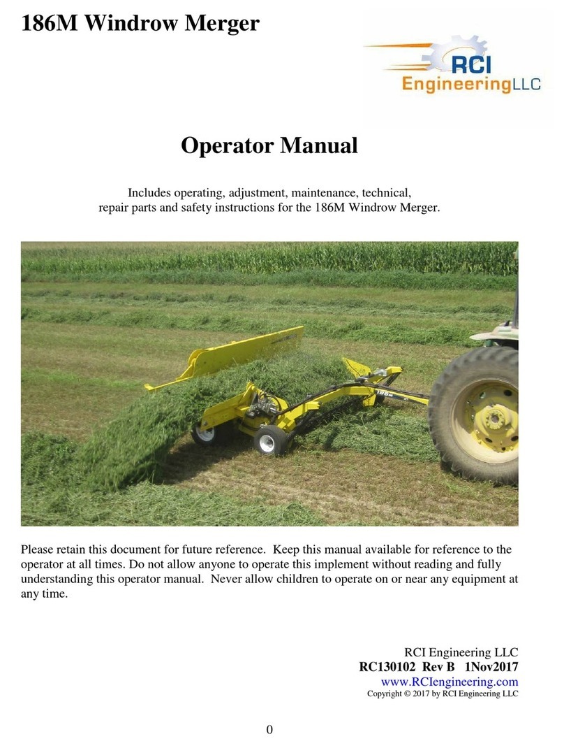
RCI AG-BAG T7170 Product manual

0
T7170, T7270 and T7060 Ag-Baggers
(T7170 Ag-Bagger S/N 0401054 - )
Operator and Parts Manual
(For Repair Parts, see Page 102)
Includes installation, operating, adjustment, maintenance, technical,
repair parts and safety information for the T7270, T7170 and T7060 Ag-Baggers
Please retain this document for future reference.
A Color PDF copy of this document is available online for download.
bit.ly/OperManual
Ag-Bag by RCI
RCI Engineering
www.ag-bag.com
Copyright © 2023 by RCI Engineering LLC
AB3171234 Rev A (20Jan23)

1
1 WARRANTY STATEMENT
Ag-Bag by RCI New Agricultural Equipment
Ag-Bag by RCI, LLC, hereinafter referred to as Ag-Bag, warrants new Ag-Bag by RCI
Equipment, to the Original Retail Purchaser to be free from defects in material and
workmanship for a period of one (1) year from the date of sale.
Ag-Bag by RCI warranty includes:
Genuine Ag-Bag by RCI parts costs and labor required to repair or replace equipment at
the selling dealer’s business location.
AG-BAG BY RCI MAKES NO REPRESENTATIONS OR WARRANTIES OF ANY KIND,
EXPRESSED OR IMPLIED (INCLUDING THE IMPLIED WARRANTIES OF
MERCHANTABILITY AND FITNESS FOR PARTICULAR PURPOSE), EXCEPT AS
EXPRESSLY STATED IN THIS WARRANTY STATEMENT.
AG-BAG BY RCI WARRANTY DOES NOT INCLUDE:
1. Transportation to the selling dealer’s business location or, at the option of the Original
Retail Purchaser, the cost of a service call.
2. Freight costs above standard shipping costs for the replacement parts.
3. Used equipment.
4. Components covered by their own non-Ag-Bag warranties, such as tires and trade
accessories.
5. Normal maintenance service and expendable, high-wear items.
6. Sacrificial components designed to fail to prevent damage to other components when
obstructions are encountered (i.e., shear bolts, rotor teeth)
7. Repairs or adjustments caused by improper use; non-intended use; failure to follow
recommended maintenance procedures; use of unauthorized attachments; accident or
other casualty.
8. Liability for incidental or consequential damages of any type, including, but not limited to
lost profits or expenses of acquiring replacement equipment or damage to machines to
which the attachment is installed.
No agent, employee, or representative of Ag-Bag by RCI has any authority to bind Ag-
Bag by RCI to any warranty except as specifically set forth herein. Any of these
limitations excluded by local law shall be deemed deleted from this warranty; all other
terms will continue to apply.

2
THIS PAGE INTENTIONALLY LEFT BLANK

3
2 TABLE OF CONTENTS
Section
Contents
Pg
Section
Contents
Pg
1
Warranty Statement
1
Conveyor Chain
58
2
Table of Contents
3
Hydraulic Pump Drive Chain
59
3
Marketing Bulletin
4
Forage Distributor Position
60
Machine Specifications
6
Rotor Drive Chain
61
4
Safe Operation of Machine
8
Bag Boom
62
Power Shut Down Procedure
10
Bag Cradle
63
5
Safety Warning Signs
11
Tunnel Cleanout and Stripper Bar Plate
64
6
Safety Sign Locations
13
Brake System Accumulator Pressure
66
7
Component Locations
14
Changing Tunnels
66
8
Operating the Unit
15
11
Lubrication and Maintenance
67
Pre-Operation Checklist
15
Tire Air Pressure
67
Backstop Setup
16
Wheel Lug Nut Torque
67
Moving Wheels to Ag-Bagging Position
18
Wheel Bearings - Repack
67
Hitch Adjustment
22
Wheel Bearings - Greasing
68
Inoculant Applicator Connection
23
Rotor Bearings
69
Bag Boom Adjustment
23
Rotor Drive Jackshaft Bearings
69
Tunnel Extension Installation
24
Forage Distributor Bearings
69
Bag Identification
25
Cable Drum Shaft Bearings
70
Bag Installation
25
Conveyor Bearings
71
Seal the Beginning End of the Ag-Bag
28
Conveyor Slides
71
Attach the Backstop
29
Conveyor Cleanout
72
Lower Conveyor to Operating Position
30
Rotor Drive Chain
73
Set Brake Pressure
32
Jackshaft Coupler Chain
73
Verifying Cleanout Closed
33
Hydraulic Pump Drive Chain
74
Ag-Bagging Operation
34
PTO Shaft
74
Sweeping Tunnel Cleanout Operation
36
Bag Boom Pivot
75
Backstop Removal
37
Hydraulic Oil Level Check
76
Removing the Ag-Bag from the Ag-Bagger
38
Hydraulic Oil Change
77
Venting the Ag-Bag
39
Hydraulic Oil Filter
78
Moving Wheels to Transport Position
40
Gearbox Oil –T7170 and T7060 Only
79
Tunnel Storage
44
Gearbox and Planetary Oil –T7270
Only Only
80
Backstop Storage
45
Cable Drum Brake Pads
81
Transporting the Ag-Bagger
47
Cables
83
9
Performance Optimization
49
PTO Shear Bolts
83
Conveyor Position
49
Brake System Oil
84
Tractor Setup
50
Rotor Tooth Tine Caps
85
Crop Conditions
50
Stripper Bar Plate
86
Ag-Bag Site
51
12
Service
87
Ag-Bagging Surface
51
Torque Specifications
87
Ag-Bag Installation
51
Hydraulic Fittings
88
Ag-Bagging Pressure
52
Hydraulic System Pressure
89
Correcting Ag-Bag Stretch
52
Lubrication Specifications
89
Sealing and Venting
52
14
Theory of Operation
90
Wind Damage
53
Hydraulic System
90
Bad Weather Ag-Bags
53
Electrical System
94
Ag-Bag Shape
53
15
Troubleshooting
95
Ag-Bag Management and Inspection
53
16
Storage
96
Suggested Feed Out Rates Per day
54
17
Set-Up and Assembly
97
Capacity of Tons per Running Foot of Ag-Bag
54
18
Repair Parts
102
Genuine Ag-Bag Capacity Chart
55
19
Pre-Delivery Checklist
210
10
Adjustments
56
20
Delivery Checklist
211
Conveyor Position
56
21
Warranty Registration and Ack.
212
Conveyor Angle
57

4
3 Marketing Bulletin
Model T7270, T7170 and T7060
The T7270, T7170 and T7060 Pull-Type Ag-Baggers feature increased capacity and many
operational improvements. These improvements are based on dealer and customer input. The
T7170 and T7270 feature a 9’or 10’tunnel. The T7060 features a 6’, 8’or 9’ tunnel.
Key Product Improvements:
1. Single Wider Conveyor
•12” Wider for more capacity
•Taller sides for wind protection
•Stainless, replaceable, reinforced floor
•Increased reliability and less maintenance compared to previous split conveyor
system
2. Revolutionary Rotor
•Twice as many teeth with even spacing across entire rotor from center to sides
•Smaller bites of forage for continuous flow across the face of the Ag-Bagger
•Better compaction for increased density and feedstuff compaction into the Ag-Bag
•Lower starting torque under load
•Single point loading during revolution
•3-7/16” bearings at each end of rotor and jackshaft for durability and consistency
3. Forage Distributor
•Distributes forage over the entire Revolutionary Rotor for faster unloading and
increased capacity by even-filling of Genuine Ag-Bags
•Hydraulically driven with adjustable positioning
•Paddle tines at ends prevent crop build-up

5
4. Sweeping Tunnel Cleanout (T7270 and T7170)
•Hydraulic cylinders sweep remaining crop into the Ag-Bag when finished
•Reduces labor, time and plastic usage when finishing and starting a new Ag-Bag
•Reduces forage loss and increases packing at the end of each Ag-Bag
5. Removeable Stripper Bar Plates
•Bolt on design can be replaced as one complete plate or smaller sections
•Ease of access to hardware with sweeping tunnel cleanout open
6. Middle Tunnel Extension (option)
•Increase tunnel length by nearly 3 feet
•Three tunnel pieces stack on each other for transport mode under 8’6” wide
•In Ag-Bagging mode, tunnels are moved using lift system and pinned together
quickly
•Longer tunnel allows tough forages like alfalfa to be packed using tunnel for greater
density and smoother sides before moving into the Genuine Ag-Bag
7. 300-Foot Cables Standard
•Ability to fill and use 300-foot bags without using cable extensions
8. New Lift System for Bag Cradle and Tunnel Extensions
•Stores Ag-Bags and tunnel extensions on machine without climbing on the machine
9. Redesigned Backstop Lifting Points and Backstop Hooks
•Cradle can be used to lift backstop
•Backstop can be lifted with multiple devices while staying away from backstop rope
•Backstop hooks is redesigned for greater ease of rope installation
•Backstop design is improved for increased durability
10. Hydraulic Tank Redesign
•Larger tank for greater capacity and better cooling
•Easier accessibility
11. Serviceability
•Control station is in one location with all machine controls in one place
•Oil bracket to store lubrication for chain maintenance
•Easy to open shields for chain inspection
•PTO shield movement –storage locking in transport
•Integrated toolbox for convenience and storage
12. Transportation
•Hitch design changes direction placing the tunnel on the side of the road to keep the
tunnel out of the on-coming lane of traffic
•Better visibility while maintaining the 8.6-foot travel width
•Hitch safety chain is standard on all machines
13. Integrated Hydraulic Lift System (T7170 and T7270)
•Hydraulic and manual jack system standard on all machines
•Machine is lifted hydraulicly to quickly change between transport and Ag-Bagging

6
Product Specifications

7
Ordering Information:
Bundle
Description
Setup Time
Notes
T7270 / T7170
Model T7270/T7170 Pull-Type Ag-Bagger
AB3170003
T7270 Base Unit (1000 RPM)
1.5 hrs*
1-3/8 21-Spl. 1000 RPM PTO Tractor
AB3170004
T7170 Base Unit (540 RPM)
1.5 hrs*
1-3/8 6-Spl. 540 RPM PTO Tractor
AB3170594
Bundle, Base Tunnel 9'
Includes Standard Extension
AB3170591
Bundle, Base Tunnel 10'
Includes Standard Extension
AB3170628
Bundle, 9' Middle Tunnel Extension w/Pins
AB3170627
Bundle, 10' Middle Tunnel Extension w/Pins
AB3171000
Kit, Gandy
AB3171797
Yoke, T7270 Large 1000
0.5 hrs*
1-3/4 20-Spl - Dealer Installed
T7060
Model T7060 Pull-Type Ag-Bagger
AB3170006
T7060 Base Unit
1.5 hrs*
AB3170880
Bundle, T7060 8' and 9' Tunnel Completion
Includes Bag Boom and Lg. Backstop
AB3170877
Bundle, T7060 8' Tunnel
Incl. Std. Ext.; Req. Compl. Bundle
AB3170879
Bundle, T7060 9' Tunnel
Incl. Std. Ext.; Req. Compl. Bundle
AB3170889
Bundle, T7060 8' Middle Tunnel Extension
AB3170890
Bundle, T7060 9' Middle Tunnel Extension
AB3170876
Bundle, T7060 6' Tunnel
Includes 6' Backstop and 6' Std Ext
AB3171000
Kit, Gandy
*Setup time may vary depending on technician experience.
To order, contact your local Ag-Bag by RCI Dealer. For a dealer locator, visit Ag-Bag.com.
Dealers order all products from RCI directly. All parts, service and warranty matters are handled
by RCI. Warranty for these products is 1 year of parts and labor as outlined in the Ag-Bag by
RCI Warranty Statement. Visit www.RCIengineering.com for more product information, ordering,
and additional information.
RCI Engineering LLC
208 River Knoll Dr
Mayville, WI 53050
Toll free: (800) 334-7432
Ag-Bag@RCI.ag
www.ag-bag.com
www.rci.ag
RCI reserves the right to make improvements in design and changes in specifications at any time without
notice and without incurring any obligation to install them on units previously manufactured or sold.
Specifications, descriptions, and illustrative materials herein are as accurate as known at the time of
publication but are subject to change without notice.

8
4SAFE OPERATION OF MACHINE
Operator Authorization
The machine owner must provide the operator of the machine this manual and ensure
that the operator reads and understands the contents. This must be performed before the
machine is put into operation.
Safety Alert Symbol
This safety alert symbol is used to alert the operator to the
potential for personal injury. Whenever this symbol is
noticed in this manual or on the machine, be alert to the
situation and read the message near the symbol. Always be
alert for the potential for personal injury.
General Safety Precautions / Accident Prevention
Before operation of the machine each time, check the entire machine for operational and
road safety. Refer to the Operator Manual for the Tractor for all information regarding the
Tractor. This manual is for the Ag-Bagger and only covers items related to the operation
of the Ag-Bagger.
1. The warning and safety decals on the Ag-Bagger provide important information to
ensure safe operation of the machine. Always read and follow these instructions
and remain safe.
2. Familiarize yourself with all controls of the machine and tractor as well as the
function of the unit before operation of the Ag-Bagger.
3. Check all guards and shields to make sure they are in place and functional.
Replace any defective or missing guards, shields, or components before operation.
4. Avoid loose fitting clothing. The operator should always wear close-fitting clothing
and sturdy footwear.
5. When traveling on public roads or transporting the machine, obey all regulations
for the area. See the Transporting the Ag-Bagger section for more information on
proper machine setup for transportation.
6. Before starting the tractor each time, the machine is operated, inspect the area
around the machine. Ensure that no one is close to the machine for bystander
safety.
7. Keep clear of the working and danger area of the machine.
8. Use caution when working on moveable components of the machine. There are
many pinch and shear points.

9
General Safety Precautions / Accident Prevention Continued
9. Know how to stop Ag-Bagger operation BEFORE starting the machine.
10.DO NOT enter the conveyor or hopper while the machine is operating or any time
the PTO is still connected to the tractor or before following the Power Shut Down
Procedure on the next page.
11.DO NOT unclog, adjust, lubricate or service your Ag-Bagger until following the
Power Shut Down Procedure on the next page.
12.Do not allow any riders on the machine nor step onto the machine during use.
13.Avoid high pressure fluids. Escaping fluid under pressure can penetrate skin
causing serious injury.
14.Wear appropriate eye and hearing protection for the equipment being used.
15.DO NOT exceed a maximum towing speed of 25 mph (40 kph) while transporting
the Ag-Bagger.
16.Reduce speed on rough or hilly surfaces.
17.Be extra careful when passing through tight areas such as farmyards, fence
gates, or other confined quarters.
18.Always follow state and local regulations regarding use of the included safety
chain, slow moving vehicle signs and transport lighting when towing any farm
equipment on public highways.
19.Only operate the Ag-Bagger on level ground.
20.Be sure the tractor is in NEUTRAL, and the parking brake released, before
beginning any Ag-Bagging operation after the Ag-Bagger is set up for Ag-
Bagging.
21.Be sure the tractor wheels are pointed in a straight-ahead position while Ag-
Bagging.
22.Do not turn the tractor and Ag-Bagger while Ag-Bagging.
23.Bure sure the hitch jack locking pin is completely engaged and that the machine
is properly blocked and prevented from rolling BEFORE disconnecting the Ag-
Bagger from the tractor.

10
24.DO NOT stand between the tractor and Ag-Bagger when hitching or unhitching
Ag-Bagger unless engine is stopped, and parking brake is engaged.
25.ALWAYS STAY CLEAR of cables, cable drums and backstop. Cables are under
tension during Ag-Bagging Operations. A fast release of tension could have
unexpected consequences.
26.ALWAYS stop Ag-Bagging operation and shut tractor off between loads if Ag-
Bagger is to be left unattended.
27.NEVER use a PTO Spline Adapter. Failure to follow this precaution may result in
machine damage, severe injury, or death. Use of an adapter will void warranty for
the Ag-Bagger due to high potential for damage to the tractor PTO, PTO
driveshaft or other Ag-Bagger components.
28.ALWAYS match the right tractor PTO spline and speed with the PTO driveshaft
provided with the implement. This will assure proper geometry and operating
speed.
29.NEVER cross over the top of the PTO shaft. NEVER touch the PTO shaft when
the tractor is running. Failure to follow this precaution may result in severe injury
or death.
30.NEVER operate 540 rpm implements at 1,000 rpm.
31.NEVER operate 1,000 rpm implements at 540 rpm.
Power Shut Down Procedure
Before cleaning, unclogging, adjusting, lubricating, or servicing this Ag-Bagger:
1. Disengage the tractor PTO.
2. Deactivate hydraulic controls.
3. Shut off the tractor engine, remove the ignition key, and take it with you.
4. Wait for all machine motion to stop.
5. Remove the telescoping PTO driveline and ALL power connections from the
tractor.
Failure to follow these precautions may result in serious injury or death.

11
5 SAFETY WARNING SIGNS
Safety Messages
Whenever the words and symbols shown below are used in this manual or on the
machine, the instructions MUST be followed as they relate to personal safety.
Safety Decal (1). Manual Reference. Before operating the
machine, make sure to read this manual in it’s entirety.
Safety Decal (2). This safety sign is a warning of missing
shields, covers, or other components. Keep clear of this area
and replace the missing components before operation.
Consult the operator manual and parts pages to determine
what components are missing and replace accordingly.
Failure to do so may result in serious injury.
Safety Decal (3). Rotating parts hazard. This safety decal is
a warning of moving and rotating parts. Keep all body parts
and clothing a safe distance from the machine during
operation. Shut off the machine before performing any
service on the machine.
Safety Decal (4). Rotating and moving parts hazard. This
safety decal is a warning of moving and rotating parts. Keep
all body parts and clothing a safe distance from the machine
during operation. Do not stand on components. Shut off the
machine before performing any service on the machine.
Safety Decal (5). Entanglement hazard. This safety decal is a
warning of rotating parts that may cause entanglement. Keep
all body parts and clothing a safe distance from the machine
during operation. Shut off the machine before performing any
service on the machine.
Safety Decal (6). Auger or rotor entanglement hazard. This
safety decal is a warning of rotating parts that may cause
entanglement. Shut off the machine before performing any
service on the machine in this area.
Safety Decal (7). This safety sign is a warning of injury due to
high temperature surface. Keep away from this area when
the machine is in use or has been used recently to avoid the
hazard. Failure to do so may result in serious injury.

12
Safety Decal (8). This safety sign is a warning of injury due to
escaping hydaulic fluid undeer presssure. Keep away from
this area when the hoses have hydraulic pressure to avoid the
hazard. Failure to do so may result in serious injury.
Safety Decal (9). This safety sign is a warning that the surface
is not to be used as a step. To avoid the hazard, do not step
on the surface. Failure to do so may result in serious injury.
Safety Decal (10). This safety sign is a warning of injury due to
a pinch or shear point. Keep feet clear of this area to avoid the
hazard. Failure to do so may result in serious injury.
Safety Decal (11). This safety sign is a warning to NOT tow
the implement over 25 MPH (40 kph). Keep towing speeds
under this speed to avoid the hazard. Failure to do so may
result in serious injury.
Safety Decal (12). This safety sign is a warning to keep the
PTO speed at the rated speed of 540 RPM or 1000 RPM. Do
not overspeed the implement to avoid the hazard. Failure to
do so may result in serious injury and / or machine damage.
SMV - Slow Moving Vehicle Decal (14). This SMV decal must
be visible on the back of the machine during road transport.
See local DOT regulations for details.
Optimum Crop Flow Reminder. Located above the rotor in the
hopper. See Performance Optimization section in this manual
for more information.

13
6 SAFETY SIGN LOCATIONS
All decals shown in locations correspond
to Safety Decals on previous pages.
Figure 1. Front View of Machine
Figure 2. Hitch End of Machine
Figure 3. Hitch
Figure 4. Rear Corner View of Machine
Figure 5. Service Compartment
Figure 6. Driveline Compartment
Figure 7. Rotor Idler End Compartment
Figure 8. Chain Conveyor Cleanout

14
7 COMPONENT LOCATIONS
Figure 9. Ag-Bagger Shown in Transport Configuration
with Tunnel Extension in Mounted Position (for clarity)
Key 1 –Bag Boom Key 2 –Bag Cradle Key 3 –Tunnel and Extension
Key 4 –Backstop Key 5 –Taillight Bar Key 6 –Cable Drum Key 7 –Lift Jack
Key 8 –OM Holder Key 9 –Storage Compartment Key 10 –PTO Storage Location
Key 11 –Conveyor Key 12 –Lift Jack Key 13 –Hitch Key 14 –Safety Chain
Figure 10. Operator Station Figure 11. S/N Tag Location
Key 1–Oil Storage Key 2 - Control Levers (inside compartment)
Key 4 - Brake Hand Pump Key 1 –S/N Tag

15
8 Operating the Unit
Pre-Operation Checklist
The pre-operation checklist is provided
for both personal safety and maintaining
the mechanical condition of the Ag-
Bagger.
Make sure each item on the list is
checked prior to operating the Ag-
Bagger each time.
Check that the tractor is properly
sized to operate the Ag-Bagger.
Refer to Machine Specifications
section.
Check that the tractor is properly
attached to the Ag-Bagger.
Check that the PTO shaft is properly
secured to the Ag-Bagger gearbox
input shaft and the tractor PTO shaft.
Check that the tires are properly
inflated and installed properly. See
Tire Air Pressure in Lubrication and
Maintenance section for
specification.
Lubricate, grease, and check all fluid
levels. Refer to the Lubrication and
Maintenance section of this manual.
Check that the grease gun has
adequate grease and that a full oil
bottle is in the holder at the operator
area near the Ag-Bagger controls.
Check the inoculant applicator (if
equipped). Make sure it is properly
connected and filled.
Check all safety shields and guards
are closed and secured in place.
Check the rotor, conveyor, hopper,
and tunnel cleanout (if equipped) to
ensure there are no foreign objects.
Check the tunnel cleanout is
completely closed.
Check the conveyor chain for correct
tension.
Check if tunnel extension(s) is (are)
properly installed.
Check each brake disc. Each disc
must be clean and rust free. Clean
as needed.
Check the cables to ensure they
have no damage and are properly
wrapped on the cable drums.
Check all hydraulic lines, hoses, and
fittings for leaks and tightness.
Check that the bag cord, bag ban
cords, and backstop rope are all in
good condition and properly
installed.
Check that the bag boom is properly
adjusted for height and pulley
position. See Bag Boom in the
Adjustments section.
Check that the hydraulic lift jacks are
in the raised position for storage and
that the lockout us used. See
Hydraulic Lift Jack Operation
section.
Check that the machine is clean and
free of any debris.
Check that this Operator Manual is
present in the Operator Manual
holder on the Ag-Bagger.

16
Backstop Setup
Place the Ag-Bagger where the bag will
begin.
Release the cable drum brake pressure
by opening the needle valve and the
hand pump valve. See Figure 12.
Unhook the backstop slings from the
cables at each side of the machine.
Remove the pins that retain the
backstop to the support feet.
Keep the stabilizer arms attached
between the backstop and the main
frame until a lifting device is attached.
See Figure 13.
Figure 12. Brake System Control
Key 1 –Hand Pump
Key 2 –Pressure Gauge
Key 3 –Needle Valve
Key 4 –Pump Valve
Figure 13. Backstop Storage Position
Key 1 –Backstop Key 2 –Pin
Key 3 –Backstop Sling and Cable
Key 4 –Stabilizer Arm

17
There are several lifting methods (Fig.
14) available to move the backstop from
storage position to Ag-Bagging position:
•Bag boom cradle (Figure 15)
oReverse boom and use tube
at front of cradle at hooks on
back side of backstop
•Forks
oUse skid steer or telehandler
with forks in fork loops at top
from rear
oUse single fork in pocket from
end of backstop
•Bucket edge
oUse bucket edge at 4 hooks
at rear of backstop
•Bag boom hook
oUsing a ladder, safely access
single hook point at bag
cradle and secure to the hook
in the center of the backstop
•Manually
oWith the help of an assistant,
manually lift each end down to
ground, 1 side at a time.
Using one of the methods above, lift the
backstop gently to support the weight of
the backstop so it is secure and stable.
Remove the stabilizer arm at each side
of the backstop and secure to the
backstop in storage position with pin.
Using the lifting device, remove the
backstop and move the Support Feet at
the bottom of the tunnel to the pockets
at backstop, with the tabs to the rear.
Install the pins back into the tabs at the
support feet. Install the tunnel pins for
the support feet in the handles of the
support feet pins. See Figure 16.
Figure 14. Backstop Lifting
Key 1 –Backstop Key 2 –Fork Pocket
Key 3 –Fork Loop
Key 4 –Single Hook Point
Key 5 –Bag Cradle and Bucket Hook
Key 6 –Bucket Hook
Figure 15. Backstop with Cradle
Key 1 –Cradle Key 2 - Backstop
Figure 16. Backstop in Use
Key 1 –Support Feet Key 2 –Pins
Key 3 –Tabs Key 4 –Pockets
Key 5 –Stabilizer Arm Key 6 - Pin

18
Moving Wheels to Ag-Bagging
Position and Connecting Tractor
NOTE:
Backstop must be placed at the starting
position of the bag. Ag-Bagger must be
on a firm, level site to move wheels and
hitch.
IMPORTANT:
Site for moving wheels must be level to
prevent Ag-Bagger from rolling when
unhitched from the towing vehicle.
Ground conditions must be firm to
prevent lift jacks from settling during
wheel removal.
Remove the pin and rotate the lift jack on
the tow hitch to the down position. Fasten
the lift jack to the hitch in the down
position for lifting.
Remove the machine from the towing
vehicle. Lower the jack stand to the
highest position possible for the current
hitch height.
Lower the hitch to rest the machine on
the jack stand and remove all pressure
on the lift jack.
Remove the lift jack from the hitch.
Remove the cross pin on the hitch and
remove the hitch from the machine.
Relocate the hitch to the Ag-Bagging side
of the machine and reinstall with cross
pin. Handles are provided for ease of
moving the hitch.
Install lift jack on hitch and raise to
appropriate height for the tractor.
See Figures 17 and 18.
Figure 17. Hitch in Transport Position
Key 1 –Hitch Key 2 –Lift Jack
Key 3 –Jack Stand
Key 4 –Hitch Cross Pin
Key 5 –Jack Stand Cross Pin
Figure 18. Hitch in Ag-Bagging Position
Key 1 –Hitch Key 2 –Hitch Cross Pin
Key 3 –Lift Jack
Key 4 –PTO Tractor End
Key 5 –PTO Shield

19
Install tractor on Ag-Bagger and install
appropriately sized hitch pin. Turn tractor
off, ensure in park, and remove key.
For the T7270 and T7170, remove lift
jack, rotate 90 degrees and place into
transport position on the hitch using
cross pin provided.
For the T7060, or to use manual lifting,
install the lift jack at the towing hitch end
wheel lift position. Move the second lift
jack from storage position to the wheel lift
position at the back side of the machine.
Remove the PTO shaft from the storage
position and install between the tractor
and the Ag-Bagger.
Push all the way on each shaft and then
release the locking collar to lock in place.
Ensure that the PTO shaft is locked onto
both the gearbox input shaft and the
tractor PTO shaft.
Release the rubber latch and lower the
PTO shaft guard down to the operating
position over the gearbox end of the PTO
shaft. Attached the anti-rotation chain of
the PTO shield to the slot provided in the
cover. Attach the other anti-rotation chain
at the tractor end to the tractor as
available. See Figure 19.
For the T7060 and for manual raising,
use the jacks to lift the wheels at the rear
wheel drops. One jack is from the hitch
and the other is stored at the near the
storage compartment. See Figures 20
and 21.
For the T7060, skip the next steps until
indicated.
Figure 19. Hitch on Tractor
Key 1 –Hitch Key 2 –PTO Chain
Key 3 –PTO Guard
Key 4 –Rubber Latch Key 5 - PTO
Figure 20. Lift Jack Storage
Key 1 –Lift Jack
Key 2 –Storage Compartment (ref)
Fig. 21. Lift Jack Usage
Key 1 –Wheel Drop Key 2 –Cross Pin
Key 3 –Lift Jack
This manual suits for next models
2
Table of contents
Other RCI Farm Equipment manuals
Popular Farm Equipment manuals by other brands

Kverneland
Kverneland ACPND 65929 Series Technical & service manual

Topcon
Topcon OPUS A8 STANDARD Basic Technical data sheet

GEA
GEA AutoSelect 3000 Original instructions

Agria
Agria 900 Original operating instructions

Prointegra
Prointegra Meteobot user manual

CAMPAGNOLA
CAMPAGNOLA STARBERRY MD2 Use and maintenance manual

Arrowquip
Arrowquip PORTABLE Q-CATCH 74 Series product manual

Evh
Evh Hardee HR2360 Operator and maintenance manual

aivituvin
aivituvin XZ7002 instruction manual

Toro
Toro E-Z Vac Z Master Z400 Series Operator's manual

LeeBoy
LeeBoy L600 Operation, service and parts manual

Ferrari
Ferrari FUTURA 2016 Operating and service manual