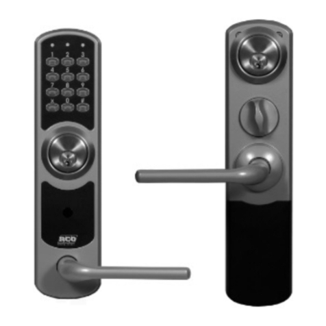
RCO R-COD 500 Training manual

R-COD
RCO Security AB
Box 705
176 27 Järfälla
tel 08-546 560 00
info@rco.se
www.rco.se © 2021 RCO Security AB. All rights reserved. February 2021.
R-COD 500 & 500 IR
Installing, Commissioning, Using
The manual describes how to mount, connect, program and
use the devices.

CONTENTS
2
Code lock R-COD 500 and R-COD 500 IR ............................................................... 3
R-COD 500 front panel........................................................................................................3
R-COD 500 IR front panel....................................................................................................3
R-COD 500 daily use............................................................................................ 4
R-COD 500 IR daily use ........................................................................................ 4
Mounting............................................................................................................ 5
Keep in mind when mounting R-COD 500 IR ......................................................................5
Surface mounting ................................................................................................................5
Mounting with recessed box .............................................................................................. 6
Connection ......................................................................................................... 7
Commissioning ................................................................................................... 8
Overview............................................................................................................................. 8
Activate IR codes (R-COD 500 IR) ...................................................................................... 8
Reset individual IR codes (R-COD 500 IR) .......................................................................... 9
General information about programming R-COD 500 and R-COD 500 IR ....................... 10
Changing the system code ................................................................................................ 10
Programming access codes ................................................................................................ 11
Erasing one access code..................................................................................................... 11
Adjusting the door opening time ....................................................................................... 12
Performing a factory reset ................................................................................... 13
If the system code is known............................................................................................... 13
If the system code is not known ....................................................................................... 13
Specifications ....................................................................................................14

R-COD 500 & R-COD 500 IR
CODE LOCK R-COD 500 AND R-COD 500 IR
3
Code lock R-COD 500 and R-COD 500 IR
R-COD 500 is a compact code lock for controlling a single door. R-COD 500 has 8 code
positions for access codes (3–6 digits each) plus 1 system code. The model R-COD 500 IR
also has positions for five IR codes for the built-in IR receiver. The IR codes are described in
a table on page 9.
R-COD 500 front panel
R-COD 500 IR front panel
The red figure blinks when
buttons are pressed and
shines steadily when the
unit is in menu mode.
These light up when the door is unlocked
and when programming in a submenu.
The keypad is used for
programming and for
entering codes.
Lights up when the door is unlocked
and when programming in a submenu.
The red figure blinks when
buttons are pressed and when
receiving an IR code.
It also shines steadily when the
unit is in menu mode and during
commissioning (see table below).
The keypad is used for
programming and for
entering codes.
IR receiver.

R-COD 500 & R-COD 500 IR
R-COD 500 DAILY USE
4
At startup
1 blink
Normal start.
2 blinks Start with SW 1/8 ON. (All IR codes are deleted.)
During normal use 1 blink Invalid IR code.
2 blinks
Too many characters in received IR code.
3 blinks IR code deactivated.
4 blinks Incorrect IR control character.
5 blinks
Unknown IR code received.
R-COD 500 daily use
Access doors by using the keypad to enter one of the programmed access codes. Each
time a button is pressed, the left symbol blinks.
When a valid access code is entered, the door unlocks and the two right symbols blink
alternately.
R-COD 500 IR daily use
Access doors by using the keypad to enter one of the eight access codes that were
programmed. Each time a button is pressed, the left symbol blinks.
Alternatively, use an IR transmitter with one of the activated IR codes.
When a valid access code is entered/received, the door unlocks and the green figure
lights up.

R-COD 500 & R-COD 500 IR
MOUNTING
5
Mounting
Keep in mind when mounting R-COD 500 IR
•Position the code lock so that the IR
receiver (on the right side of the front
panel) is clearly visible from the where
the IR transmitter is to be used.
•Do not mount the code lock in a
position where direct sunlight hits the
IR receiver.
•Do not position the code lock near light
sources such as fluorescent lamps or
low-energy lamps.
•If access codes 5–8 are
not
going to be
time-controlled, pins 3 and 4 on
terminal P1 must be connected.
Otherwise the codes will not work.
•Contact mail services, newspaper
delivery services and others to inform
them that an IR reader is installed at
the door.
Surface mounting
(Applies to both R-COD 500 and
R-COD 500 IR.)
The drawing shows the most
commonly used measurements on the
mounting plate. All measurements are given
in millimetres.
The mounted unit measures 70 x 144 x 37 mm.
Sabotage-
kontakt
52
20
66
6,7
8,7
125
139,7
7

R-COD 500 & R-COD 500 IR
MOUNTING
6
Mounting with recessed box
1. Mount the recessed box and the
unit’s mounting plate (4 screws).
For best protection from vandalism,
mount the recessed box as close to the
surface (or spacers) as possible.
2. Connect the terminal block.
Lock the reader into place.
3. Mount and affix the frame with the
screws provided.
The frame measures
94 x 239 mm

R-COD 500 & R-COD 500 IR
CONNECTION
7
Connection
Marking Function
Relay (P1/6,7,8) Can be switched breaking (NC) or closing (NO). In the above
example, the strike plate is activated when a valid access code
or IR code is entered/received, and the connection between
pins 6 and 8 is broken.
Button (P1/5) Connecting terminals 4 and 5 activates the strike relay for the
specified door opening time.
Time control (P1/3) When pins 3 and 4 are
not
connected, the access codes in code
positions 5–8 will not work.
AC/DC (P1/1,2) Power supply.
Relay
C
NO
NC
Button
Common 0V
Time control
AC/DC
AC/DC

R-COD 500 & R-COD 500 IR
COMMISSIONING
8
Commissioning
Overview
1. Only R-COD 500 IR: Activate IR codes.
2. Change the system code (see page 10).
Do not lose the system code, or a factory reset must be performed (see page 13).
3. Set the access codes (see page 10). Use the new system code for this.
4. Adjust the door opening time if needed (see page 12).
Activate IR codes (R-COD 500 IR)
Activate IR codes using switch SW1 on the circuit
board.
ON = IR code activated.
OFF = IR code not activated.
Use the procedure:
1. Set
all
switches on SW1 to ON.
2. Power up. All IR codes are reset.
3. Set SW1/8 to OFF.
4. Test the IR function using the test transmitter
IRC212. The symbol in the middle should light
up green and the door should unlock.
5. Set SW1/6 (test code) and SW1/7 to OFF.
6. Also set terminal SW1/1 –SW1/5 to OFF for
the IR codes that are not going to be used.
!
AC/DC RELAY
TIME
0V
BUTTON
NC
NO
C
D1
D7
RE1
P3
U1
IC2
C1
C3
U2
T1
D10
D9
D8
D13
D12
D11
D16
D15
D14
IC3
87654321
ON
D19
D18
D17
SW1

R-COD 500 & R-COD 500 IR
COMMISSIONING
9
Terminal/
IR code number User/function
1 Postal service
2 Newspaper delivery service
3 CityMail
4 Advertising (SDR etc.)
5 Authorities, municipal services
6 Test transmitter for service/installation. (Requires test
transmitter IRC212.)
7 Not used. Normally set to OFF.
8 Resets codes. See instructions.
Reset individual IR codes (R-COD 500 IR)
1. Disconnect the unit from power.
2. Set the terminal for each IR code to be reset (SW1/1-5) to ON, and all others to OFF.
Only IR codes with terminal set to ON will be reset.
3. Set SW1/8 to ON.
4. Power up. The selected codes are reset.
5. Set all terminals to the desired mode.
Be sure to set SW1/8 to OFF so that the codes are not reset if the unit is
restarted.
!

R-COD 500 & R-COD 500 IR
COMMISSIONING
10
General information about programming R-COD 500 and R-COD 500 IR
Use this procedure when using the keypad to change the settings:
1. Enter the system code (default 1 2 3 4). The left symbol lights up red to confirm
entering programming mode.
2. Select the desired menu number (see below) and then #.
3. Complete the desired programming. Confirm with # and back out of the menu with *.
4. To return to operating mode, press *. The left symbol stops shining.
The unit’s LED lamps help with programming because they show which step you are at.
The following symbols are used in the instructions to show what the unit looks like
after
you do the step:
Off
(operating mode)
Red LED shining
(programming mode)
Middle green
LED shining
Righthand green
LED shining1
–
Changing the system code
The system code is used to enter the programming menu.
Change the system code upon commissioning so that no unauthorised person can use
the system code to reprogram access codes.
If the system code has fewer digits than any of the access codes, no access code may
have the same initial digits as the system code.
Description Quick guide Indication
1. Enter the system code (default 1 2 3 4). x x x x
2. Select menu 2. Confirm by pressing #. 2 + #
3. Enter the new code. Confirm by pressing #. The unit
beeps once to confirm the change.
code + #
4. Return to operating mode by pressing the asterisk. * –
1On model R-COD 500 IR (which does not have the far-right lamp), the green symbol blinks instead.
!
!

R-COD 500 & R-COD 500 IR
COMMISSIONING
11
Programming access codes
Description Quick guide Indication
1. Enter the system code (default 1 2 3 4). x x x x
2. Select menu 1. Confirm by pressing #. A beep
confirms.
1 + #
3. Select a code position (1–8). Confirm by pressing #.
When pins P1/3 and P1/4 are not connected, the
access codes in code positions 5–8 will not
work. See page 7.
1–8 + #
4. Enter the access code. Confirm by pressing #.
A beep confirms.
code + #
5. Program additional access codes (repeat steps 3–4). ...
6. Press * to return to the main menu. *
7. Return to operating mode by pressing the asterisk. * –
Erasing one access code
Description Quick guide Indication
1. Enter the system code (default 1 2 3 4). x x x x
2. Select menu 4. Confirm by pressing #. 4 + #
3. Select a code position (1–8). Confirm by pressing #.
The code in the selected position is immediately
erased. A beep confirms it.
1–8 + #
4. Return to operating mode by pressing the asterisk. * –
!

R-COD 500 & R-COD 500 IR
COMMISSIONING
12
Adjusting the door opening time
Specify how long the door is to remain open after valid access codes are entered/received.
The standard (default) time is 5 seconds.
Description Quick guide Indication
1. Enter the system code (default 1 2 3 4). x x x x
2. Select menu 5. Confirm by pressing #. 5 + #
3. Enter the time in minutes and seconds.
Example: 0115 = 1 minute and 15 seconds.
The minimum opening time is 1 second (0001).
The maximum opening time is 59 minutes and 59
seconds (5959).
Confirm by pressing #. A beep confirms the change.
x x x x + #
4. Return to operating mode by pressing the asterisk. * –

R-COD 500 & R-COD 500 IR
PERFORMING A FACTORY RESET
13
Performing a factory reset
Normally a factory reset is only performed when the unit is commission or recommissioned,
or when the system code has been lost. All information contained in the memory is erased.
The system code is reset to the default (1 2 3 4).
After a factory reset, change the system code upon commissioning so that no
unauthorised person can use the system code to reprogram access codes.
If the system code is known
Description Quick guide Indication
1. Enter the system code (default 1 2 3 4). x x x x
2. Select menu 9. Confirm by pressing #. 9 + #
3. Press 1 for master reset. 1
4. Confirm by pressing #. A beep confirms that the unit
has been reset.
# –
If the system code is not known
Description Quick guide Indication
1. Press and hold 0 when powering up the unit.2—0—
2. Press 1 and then # to confirm master reset. A beep
confirms that the unit has been reset.
1 + # –
2This assumes that power to the code lock has been interrupted. The normal procedure is to temporarily
interrupt the supply from the distribution box and get an assistant to hold down the 0 button while power is
restored. Then press 1 and then #.
!

R-COD 500 & R-COD 500 IR
SPECIFICATIONS
14
Specifications
AD/CD specification (t = +20°C) Min. Typ Max. Unit
Supply voltage DC 10 30 V
AC 8 24 V
Power consumption Idle 31 (IR) / 26 mA
Backlight on 21 mA
Relay on 24 mA
Max. total 50 71 (IR) / 66 mA
Temperature range at 24 V AC
and max. power consumption
-30 +70 °C
Current at 24 V DC Relay, single pole 1 A
Number of access codes 8 st.
Number of IR codes (only R-COD 500 IR) 5 st.
Reading distance of IR receiver (only R-COD 500 IR) 10 m
Dimensions (B x H x D) Surface mounting: 70 x 144 x 37 mm
Box for recessed mounting: 76 x 204 x 28 mm
Front frame for recessed mouting (b x h): 94 x 239 mm
Weight 0.6 kg
This manual suits for next models
1
Table of contents
Other RCO Lock manuals
Popular Lock manuals by other brands

Ghost Controls
Ghost Controls ZOMBIELOCK AXZL instructions

Garagedoor Lock
Garagedoor Lock Pro 135 A Series Installation and operating guide

Miki Pulley
Miki Pulley PSL-K instruction manual

Simons Voss Technologies
Simons Voss Technologies SI SmartLocker AX manual

Kaba
Kaba SIMPLEX EE1000 Series installation instructions

Schlage
Schlage AD-Series installation instructions