RCO NoKey Force Series Wiring diagram

R-CARD 5000
Installing and operating NoKey force:
•K01
•K03
•KC03 Oval cylinder
•KC03 Round cylinder
•KC02
NoKey Force
Installing and Operating
April 2019
© 2019 RCO Security AB. All rights reserved.

2
Contents
Safety and environment...................................................................................................................................... 3
General...................................................................................................................................................................... 4
Installing NoKey force with round cylinders .............................................................................................. 5
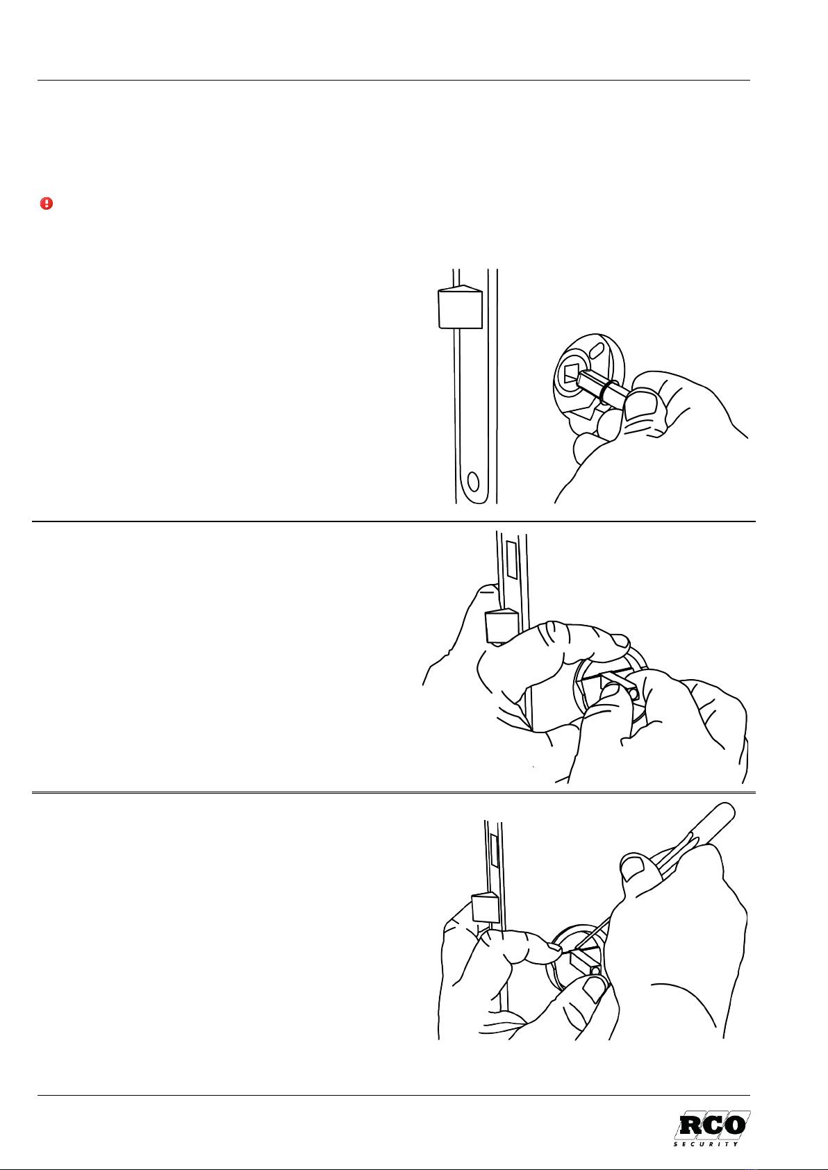
1Checking the placement of the lock housing; altering the length of the square pin ........... 6
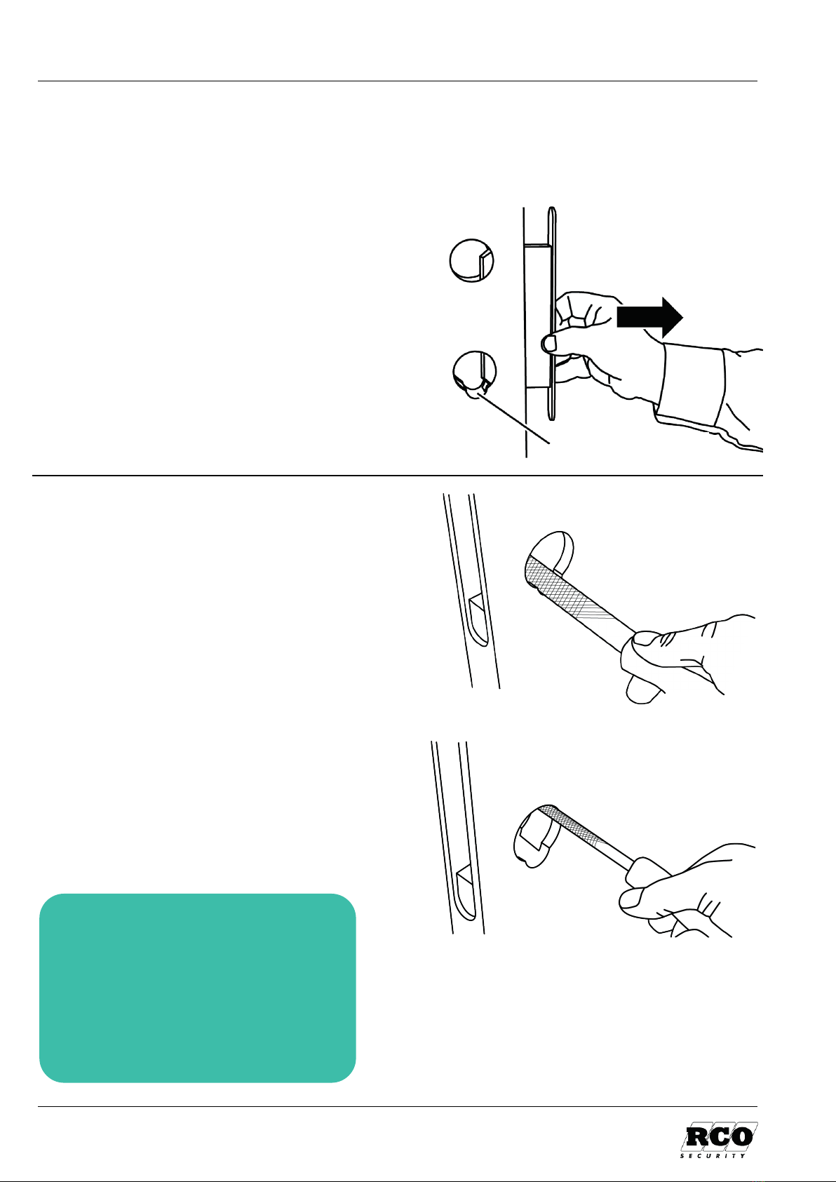
2Adjusting the handle hole and/or recess for the lock housing................................................... 8
3Adapting for left-hinged doors............................................................................................................... 9
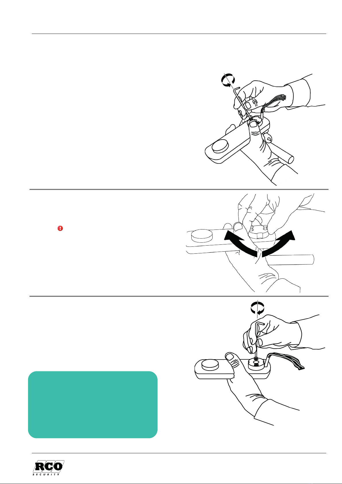
4Installing the outer and inner unit .....................................................................................................10
Models K01 and K03, without cylinders .........................................................................................................10
Model KC03, with cylinder on the outside of the door.............................................................................. 16
Model KC02, with round cylinders on the inside and outside of the door ........................................23
The latch bolt can protrude ............................................................................................................................28
5Programming the code lock..................................................................................................................29
General .........................................................................................................................................................................29
Entering codes to unlock the door ....................................................................................................................29
Changing access codes ...........................................................................................................................................30
Deleting access codes .............................................................................................................................................30
Activating/deactivating sound when unlocking..........................................................................................30
Adjust how long the door stays unlocked.......................................................................................................31
Activating/deactivating sound when battery is low ..................................................................................31
Changing the system code ....................................................................................................................................31
Entering a code for activating/deactivating zero opening ......................................................................32
Activating zero opening.........................................................................................................................................32
Deactivating zero opening....................................................................................................................................32
Activating/deactivating code attempt limitation ........................................................................................ 32
Factory resetting ......................................................................................................................................................33
Appendix 1: Signals in NoKey force ..............................................................................................................34
Appendix 2: Specifications...............................................................................................................................35
Table for your own codes.................................................................................................................................36

NoKey Force – Installing and Operating Safety and environment
3
Safety and environment
Safety provisions
Only high-quality alkaline batteries may be used. Using other types of batteries may be hazardous.
If the product is installed according to the instructions, no particular safety regulations need to be
observed.
CE marking
This product meets all relevant product safety requirements and is CE
marked. The CE marking is on the back of each unit.
The marking is repeated on the inside of the unit's battery cover.
Environment
The environmental declaration is available at www.rco.se.
Building product declaration
The building product declaration is available at www.rco.se.
Batteries
If the lock is fitted with batteries, all spent batteries must be waste sorted and taken for separate
collection. Further information can be obtained from the local authorities responsible for waste
management.
Battery specifications
Type
Position
5 x LR6 AA alkaline batteries
Battery cover
1 x 9V alkaline battery
Emergency power via outside of door
RoHS/WEEE
The product meets all applicable regulations in accordance with RoHS/WEEE and REACH.
Recycling
The product is marked with the crossed-out waste bin, and can be sent to RCO for
recycling or sent for recycling in accordance with local provisions.

General NoKey Force – Installing and Operating
4
General
NoKey force is a battery-operated code lock that easily complements existing lock casings and
handles with the option to control entry access using codes.
To unlock and permit access, enter a pre-programmed code. When a valid code is entered, a distinct
click is heard, the green LED illuminates (and if activated, a brief beep is also heard) and the door
can be opened by pushing down the handle.
From the inside, the door is opened by pushing down the handle in the normal way.
Ensure that doors with electric locking can also be unlocked mechanically.
Emergency power is provided via a 9-volt battery connected to contacts on the underside of the
external unit. This option is intended for use if the unit’s normal AA batteries are entirely spent. All
codes will work in this mode.
The codes also remain when batteries are changed.
NoKey force models
Model
Cylinder
Knob
K01
–
–
K03
–
KC03 Oval cylinder
KC03 Round cylinder
KC02
1
Recommendation: Download the
information sheet Låshus per modell (in
Swedish) from RCO:s website! The info
sheet uses a matrix to illustrate suitable lock
housings for each NoKey model. Some lock
housings require a butterfly adapter to
prevent the knob pin from jamming.
1Installed in combination with approved round cylinders on the inside and outside of the door. Small knob on the
inside. Always locked when you leave, even if the cylinder lock is not used. Suitable for houses and apartments.
A butterfly adapter is recommended
with this type of cylinder,
particularly if the door is thick
A butterfly adapter is required
with this type of cylinder
Butterfly adapter
(fjärilsroddare or roddaradapter)
RCO part number 20 180 818

NoKey Force – Installing and Operating Installing NoKey force with round cylinders
5
Installing NoKey force with round cylinders
When installing NoKey force KC02 or KC03 together with a round cylinder, there is nothing fixing
the unit’s upper section to the door leaf, as with the cylinder ring when installing with an oval
cylinder. The unit is therefore fitted with two ‘barbs’ which fix the upper section to the lock cylinder
and door leaf.
First ensure that the lock cylinder with the correct
cylinder extender is fitted
but can still move
towards the lock housing. When installing NoKey
force, tighten the lower screws (by the handle) so
that the unit is fixed to the door leaf.
Then continue with the Allen screws (2.5mm)
which activate the ‘barbs.’ Ensure that the unit is
not pulled up/down or sideways by the ‘barbs.’
This can lead to the handle sticking, as the square
pin then pinches against the lock housing. There is
negligible risk of this happening if the lock cylinder
can still move against the lock housing.
Ensure correct function by tightening the Allen
screws clockwise in turn (upper – lower/right –
left) whilst feeling to check the handle on the inside
is not sticking.
When the unit is close to the door leaf, check that
the lower screws are sufficiently tight. Then finally
fully tighten the lock cylinder.

Checking the placement of the lock housing NoKey Force – Installing and Operating
6
1 Checking the placement of the lock housing; altering the length
of the square pin
This section ensures that a good mechanical function is achieved, regardless of the NoKey model.
Note: If the door leaf is 39 mm or thinner, a spacer plate must be fitted to the rear of the inner
unit. To be ordered from RCO Security (item no 20 180 815). Hold it against the door leaf when
placing the gauge and defining the length of the square pin.
1.1
Insert the square pin with the rounded
end towards the lock housing.
1.2
Use the included gauge.
Check that the square pin runs easily
through the gauge and lock housing.
If not, the handle hole must be
adjusted – see page 8.
1.3
Push the square pin in to the lock
housing.
Make a mark on the square pin at the
level of the gauge.
Inside of door

NoKey Force – Installing and Operating Checking the placement of the lock housing
7
1.4
Cut the square pin to the correct length
as per the mark.
Make sure the cut is at a right angle.
Smooth off the cut face with a suitable
tool.
1.5
After cutting, check with the gauge
again. The end of the square pin should
be between the inner and outer edges of
the gauge.
If the end of the square pin sticks out
from the outer edge of the gauge, the
lock will stick.

Adjusting the handle hole and/or recess for the lock housing NoKey Force – Installing and Operating
8
2 Adjusting the handle hole and/or recess for the lock housing
If the gauge does not go into the handle hole, or if there is not enough space for the cable, the
necessary adjustments will have to be made.
2.1
Loosen and remove the lock housing.
Save the screws for later re-installation.
2.2
File the hole so that the cabling has
space and the gauge fits without
tension. Then re-install the lock
housing.
Now continue by adapting the unit for a
left-hinged door (see next page) or on the
following page, depending on the model:
K01 and K03: page 10
KC03: page 16
KC02: page 23
Space for cabling

NoKey Force – Installing and Operating Adapting for left-hinged doors
9
3 Adapting for left-hinged doors
The lock is set for right-hinged doors. Use the following process to adapt it for left-hinged doors.
3.1
The repositioning is achieved on the
outer unit by turning the handle and
lock mechanism.
Remove the two screws (Torx T25) that
hold the mechanism in place. Save them
for later re-installation.
3.2 Turn t
he mechanism round 180 degrees
without
lifting it, so that the handle ends
up in the right direction.
Keep the mechanism pressed down
the entire time!
3.3
Replace the screws and tighten them.
Now continue on the following page,
depending on the model:
K01 and K03: page 10
KC03: page 16
KC02: page 23

Installing the outer and inner unit NoKey Force – Installing and Operating
10
4 Installing the outer and inner unit
Models K01 and K03, without cylinders
This describes the installation of an outer unit without lock cylinder together with an inner unit
without a knob.
For installation of NoKey force KC03 go to page 16, for KC02 go to page 23!
To simplify the process for the installer, the lock is always unlocked until it is in operation.
4.1
Thread the cabling from the outer unit
through the door under the lock
housing.
Ensure there is enough space. If not,
adjustments must be made –
see page 8.
4.2
Insert a lock screw in one of the upper
holes to temporarily secure the outer
unit.
4.3
Loosen and remove the cover from the
inner unit.
(Allen 3 mm)
Save the screws for later re-installation.

NoKey Force – Installing and Operating Installing the outer and inner unit
11
4.4
If the door is thinner than 39 mm, a
spacer plate is needed on the rear of the
inner unit (see page 6.)
The spacer plate is screwed on to the
rear of the inner unit with the
accompanying screw (Torx T15).
4.5
Insert the square pin into the inner unit,
with the rounded end facing outwards.
Select the correct hex pin and insert it
past the square pin, turn it back and
forth a few times and ensure that it
grips in the mechanism.
Door thickness
Length of
hex pin
38 – 58 mm
80 mm
58 – 81 mm
100 mm
81 – 110 mm
130 mm
130 mm hex pin ordered separately.
4.6
Thread the cable with its contact
through the oblong hole down to the left
in the inner unit.
Ensure that the cable runs freely and
does not get trapped when the units are
later screwed tight.
Spacer plate
Rounded

Installing the outer and inner unit NoKey Force – Installing and Operating
12
4.7
Insert the unit with the hex pin and
square pin to the lock housing and the
outer unit.
4.8
Cut the lower lock screws as follows:
Min = door thickness + 18 mm
Max = door thickness + 26 mm
Take care to ensure the threads are not
damaged. Smooth off the cut face with a
suitable tool.
4.9
Install the lower cut lock screws, but
do
not
fully tighten them yet.
4.10
Remove the temporary upper screw.

NoKey Force – Installing and Operating Installing the outer and inner unit
13
4.11
Cut the upper lock screws as follows:
Min = door thickness + 6 mm
Max = door thickness + 11 mm
Take care to ensure the threads are not
damaged. Smooth off the cut face with a
suitable tool.
Insert the tension plate and the cut
upper lock screws.
4.12
Tighten the upper and lower lock
screws sufficiently.
4.13
Remove the transport protection by
pulling it out straight, not to the side.

Installing the outer and inner unit NoKey Force – Installing and Operating
14
4.14
Check the handle function from the
outside. The lock is always unlocked
until it is put into operation.
If something is sticking, this could be
because:
•the lock or square pin does not have
enough clearance against the door or
lock housing. Compare with the
description on page 8.
•The square pin is too long.
•Wrong square pin.
•The door's inner and outer sides are
not parallel.
•
Faulty lock housing.
4.15
Fit the contact in the circuit board.
4.16
Fold the cable double and place it under
the load holder.
Insert the batteries (5 x AA) into the
battery compartment.

NoKey Force – Installing and Operating Installing the outer and inner unit
15
4.17
Refit the cover on the inner unit. Ensure
the handle is inserted towards the
square pin.
4.18
Re-insert the four screws for the cover
and tighten.
(Allen 3 mm)
4.19
Replace the battery cover and tighten
the screws on the underside.
(Allen 2.5 mm)

Installing the outer and inner unit NoKey Force – Installing and Operating
16
Model KC03, with cylinder on the outside of the door
This describes the installation of an outer unit with cylinder together with an inner unit with a
knob.
For installation of NoKey force KC02 go to page 23!
To simplify the process for the installer, the lock is always unlocked until it is in operation.
4.1
Thread the cabling from the outer unit
through the door under the lock
housing.
Ensure there is enough space. If not,
adjustments must be made –
see page 8.
4.2
Insert a cable tie through the cylinder
hole and door leaf to temporarily
secure the outer unit.
4.3
Loosen and remove the cover from the
inner unit.
(Allen 3 mm)
Save the screws for later re-installation.

NoKey Force – Installing and Operating Installing the outer and inner unit
17
4.4
If the door is thinner than 39 mm, a
spacer plate is needed on the rear of the
inner unit (see page 6.)
The spacer plate is screwed on to the
rear of the inner unit with the
accompanying screw (Torx T15).
4.5
Insert the square pin into the inner unit,
with the rounded end facing outwards.
Select the correct hex pin and insert it
past the square pin, turn it back and
forth a few times and ensure that it
grips in the mechanism.
Door thickness
Length of
hex pin
38 – 58 mm
80 mm
58 – 81 mm
100 mm
81 – 110 mm
130 mm
130 mm hex pin ordered separately.
4.6
Thread the cable with its contact
through the oblong hole down to the
left in the inner unit.
Ensure that the cable runs freely and
does not get trapped when the units
are later screwed tight.
Spacer plate
Rounded

Installing the outer and inner unit NoKey Force – Installing and Operating
18
4.7
Insert the unit with the hex pin and
square pin to the lock housing and the
outer unit.
4.8
Cut the lower lock screws as follows:
Min = door thickness + 18 mm
Max = door thickness + 26 mm
Take care to ensure the threads are not
damaged. Smooth off the cut face with a
suitable tool.
4.9
Install the lower cut lock screws, but
do
not
fully tighten them yet.
4.10
Cut and remove the cable tie.

NoKey Force – Installing and Operating Installing the outer and inner unit
19
4.11
When the lock cylinder is fitted, you
must compensate for the thickness of
the cover (17 mm) with a suitable
cylinder extender.
Fit the lock cylinder and extender to
the lock housing.
4.12
Before the cylinder ring can be fitted,
the correct length screws must be
defined:
AFirst insert the tension plate into the
cylinder hole. Then insert the
screws to be used through the
tension plate and lock housing and
screw them in so that they go into
the cylinder ring.
BPull out the cylinder ring so that the
screws touch the bottom against the
tension plate.
CMeasure distance ‘A’.
DRemove the screws.
ECut the screws to measurement
‘A’ + 2 mm.
FReplace the screws and tighten
them.
A
B
C

Installing the outer and inner unit NoKey Force – Installing and Operating
20
4.13
Remove the transport protection by
pulling it out straight, not to the side.
4.14
Check the handle function from the
outside. The lock is always unlocked
until it is put into operation.
If something is sticking, this could be
because:
•The lock or square pin does not
have enough clearance against
the door or lock housing.
Compare with the description
on page 8.
•The square pin is too long.
•Wrong square pin.
•The door's inner and outer sides
are not parallel.
•
Faulty lock housing.
4.15
Fit the contact in the circuit board.
This manual suits for next models
5
Table of contents
Other RCO Lock manuals
Popular Lock manuals by other brands

Schlage
Schlage GF3000 Gravity Force Series installation manual

W&F-LOCKS
W&F-LOCKS 1402 "One-Timer" technical information

Axelent
Axelent Storeroom X-It Electric F Assembly manual

Yale
Yale nexTouch Installation and programming instructions

Hama
Hama 054117 operating instructions

LOX
LOX ES10 installation manual