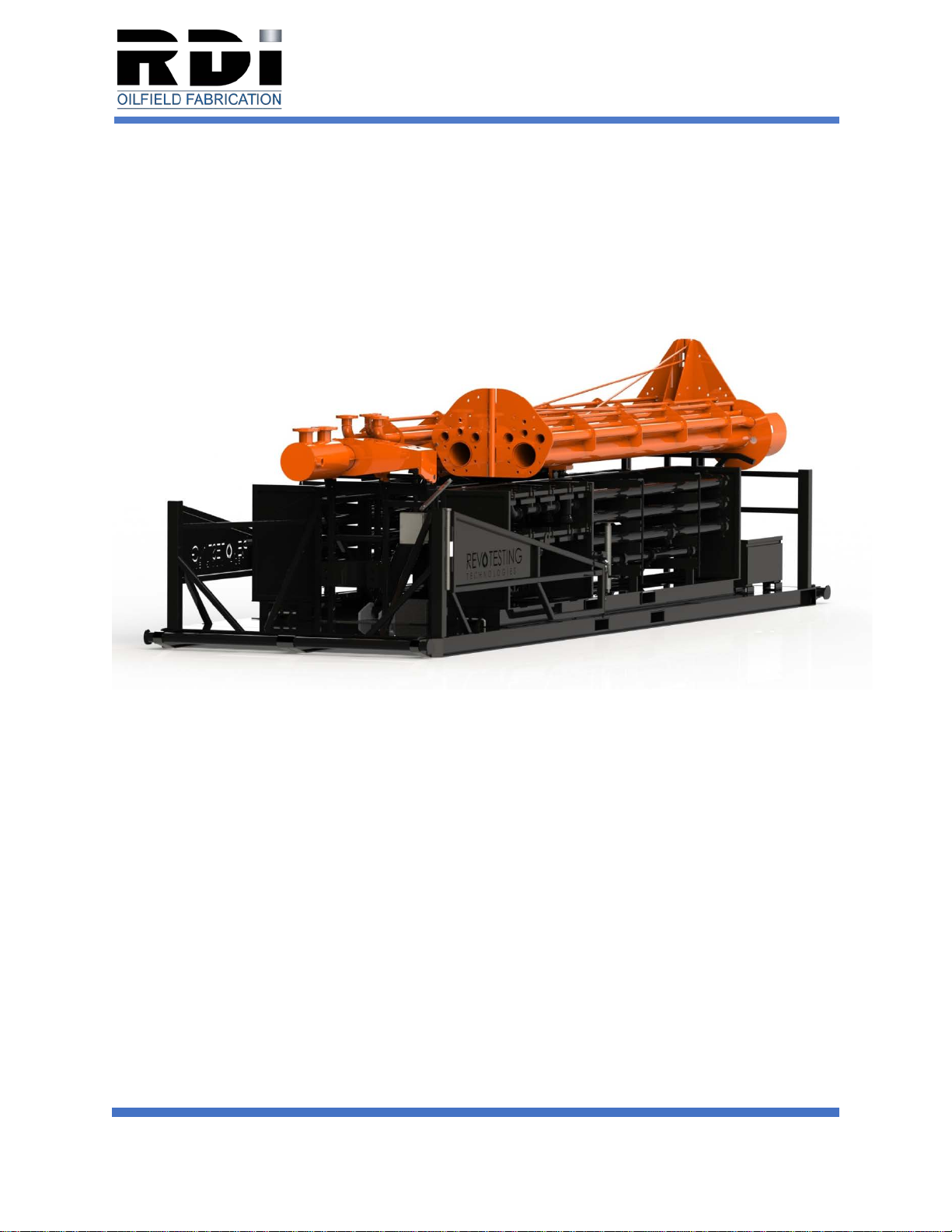
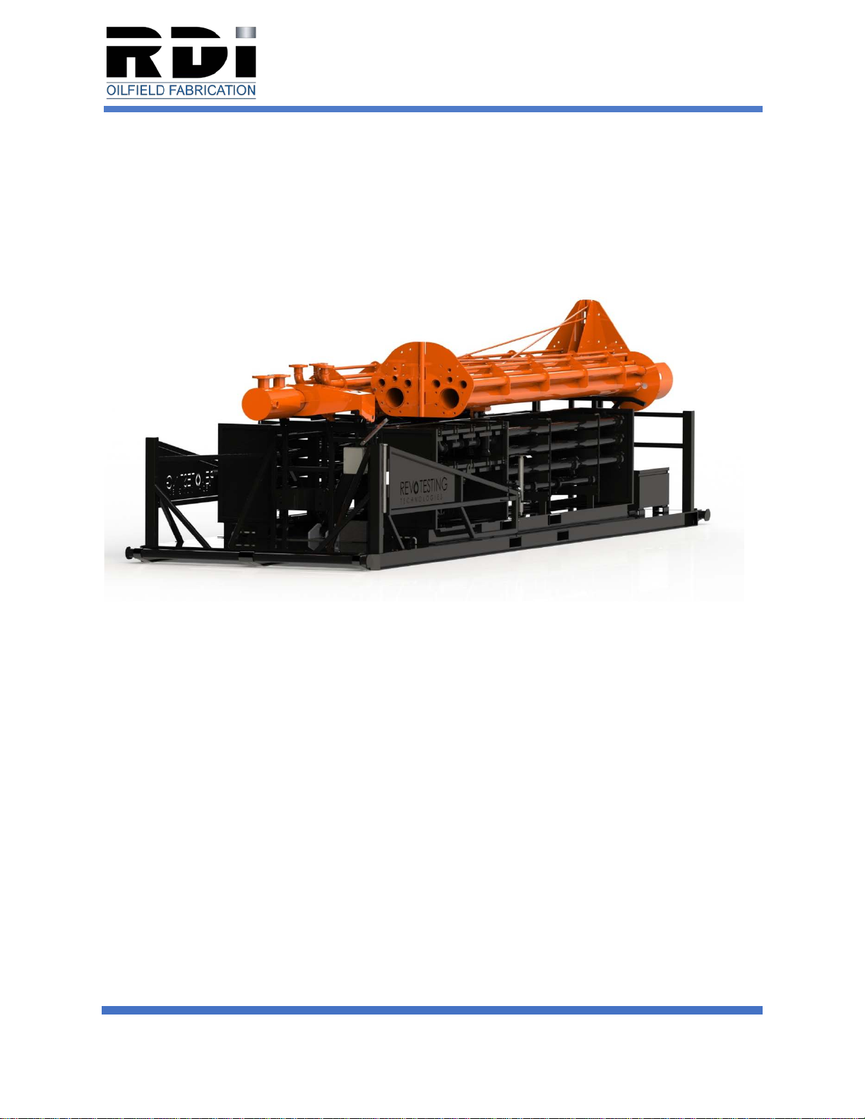
RDI 860 User manual

860 FLARE SKID
INSTALLATION AND OPERATION
1
INSTALLATION AND OPERATION MANUAL
REVISION 1.1
FOR SERVICE CALL: 970.440.3084
ATTENTION: Read this manual and all labels attached to the unit carefully before
attempting to install, operate or service your 860 Flare Skid.Record the unit model and
serial number(s) in the space provided below. Retain for future reference.
Model Number: ________________________________________________________
Serial Number: ________________________________________________________
Date of Purchase: ______________________________________________________

860 FLARE SKID
INSTALLATION AND OPERATION
2
CUSTOMER RESPONSIBILITY
This equipment has been tested and inspected. It has been shipped free from defects
from our factory and has gone through a rigorous quality control system to ensure your
complete satisfaction. However, shipment and installation problems such as loose
wires, fasteners or bolts may occur. It is the responsibility of the customer to inspect
and correct any problems that may be found prior to use.
RECEIVING INSTRUCTIONS
Inspect unit immediately when it is received to determine if any damage has occurred
during shipment. RDI is not responsible for any damages if unit was shipped via a third-
party shipping company. Check for any visible damage to the unit. If any damage is
found, the consignee should sign the Bill of Lading indicating said found damage and
immediately file a claim for damage with the transportation company. Any warranty
issues or claims need to be filed within five (5) business days of delivery and
acceptance.
WARNING: Improper installation, adjustment, alteration, service or maintenance can
cause property damage, injury or death. Read the installation, operating and
maintenance instructions thoroughly before installing or servicing this equipment.
WARNING: Install, operate and maintain unit in accordance with the manufacturers
instructions to avoid damage, injury or death.

860 FLARE SKID
INSTALLATION AND OPERATION
3
TABLE OF CONTENTS
860 FLARE SKID
Basic Description………………………………………………………………………………..4
Performance and Specification Data…………………………………………………….…4-5
Special Precautions………………………………………………………………………….….6
Standard Operating Procedures………………………………………………...…………7-12
Troubleshooting Guide………………………………………………………………………..13
Maintenance Requirements…………………………………………………………….…….14
CFR 60.18 Compliance…………………………………………………..…….…………15-23
INSPECTION WORKSHEET
ACL 3200 IGNITOR MANUAL
CROSBY CLIP INFORMATION

860 FLARE SKID
INSTALLATION AND OPERATION
4
BASIC DESCRIPTION
The 860 Flare Skid is a factory assembled hydraulic flare skid designed to burn off
excess gas for natural gas operations. These units are stand-alone units that are
designed for ease of use and relocation. DO NOT alter these units in any way. If you
have any questions after reading this manual, contact the manufacturer.
Figure 1 – 660 Pro Series Flare Trailer
PERFORMANCE AND SPECIFICATION DATA
- 40 CFR 60.18 Compliant
- ACL 3200 Incinerator Ignition System
- ASCE Wind Analysis – 90 MPH Exposure, D Wind Force
- 10 Million CFM per day
- 60’ Flare Stack
- 17” Flare Tip
- 8” Center Pipe
- 3” Pilot Tube Pipe
- (2) 2” Auxillary Pipes
- 1” Secondary Propane Clicker
- 4.8W / 12V Water Resistant Solar Panel
- 12V Hydraulically Raised Flare Stack

860 FLARE SKID
INSTALLATION AND OPERATION
5
- Triple Guy Wire Support Cables
- Heavy Duty Support Wings
- (2) Drop-Leg Jacks (10,000 LB Each)
- 1/8” Diamond Plate Decking
- (2) Removable 3” 206 Pipe Skids
- Total Skid Weight: 15,500 LBS

860 FLARE SKID
INSTALLATION AND OPERATION
6
SPECIAL PRECAUTIONS
WARNING: Failure to comply with the general safety information may result in
extensive property damage, severe personal injury or death.
WARNING: Do not alter or damage the unit. Severe personal injury or death may
occur.
Follow all installation and operation instructions CAREFULLY to avoid creating unsafe
conditions. All wiring should be done and checked by a qualified electrician. All gas
connections should be made, and leak tested, by a suitably qualified individual per
instructions in this manual. Follow all procedures listed in “Standard Operating
Procedures” located in this manual.
WARNING: Disconnect all power and gas supplies before servicing the unit. Failure to
do so could result in fatal electric shock or severe personal injury.
WARNING: Do not insert fingers or other objects into electrical compartments of the
unit. Do not block or tamper with the unit in any manner while in operation or
immediately following the unit being turned off. Some parts may be hot enough to
cause injury.
This unit has multiple pinch point hazards. Exercise extreme caution when working on
or around this unit and avoid placing fingers or extremities in these locations.
Pipe being stored or shipped on this trailer needs to be secured with pins prior to travel.
Do not attempt to move flare skid in standing position.
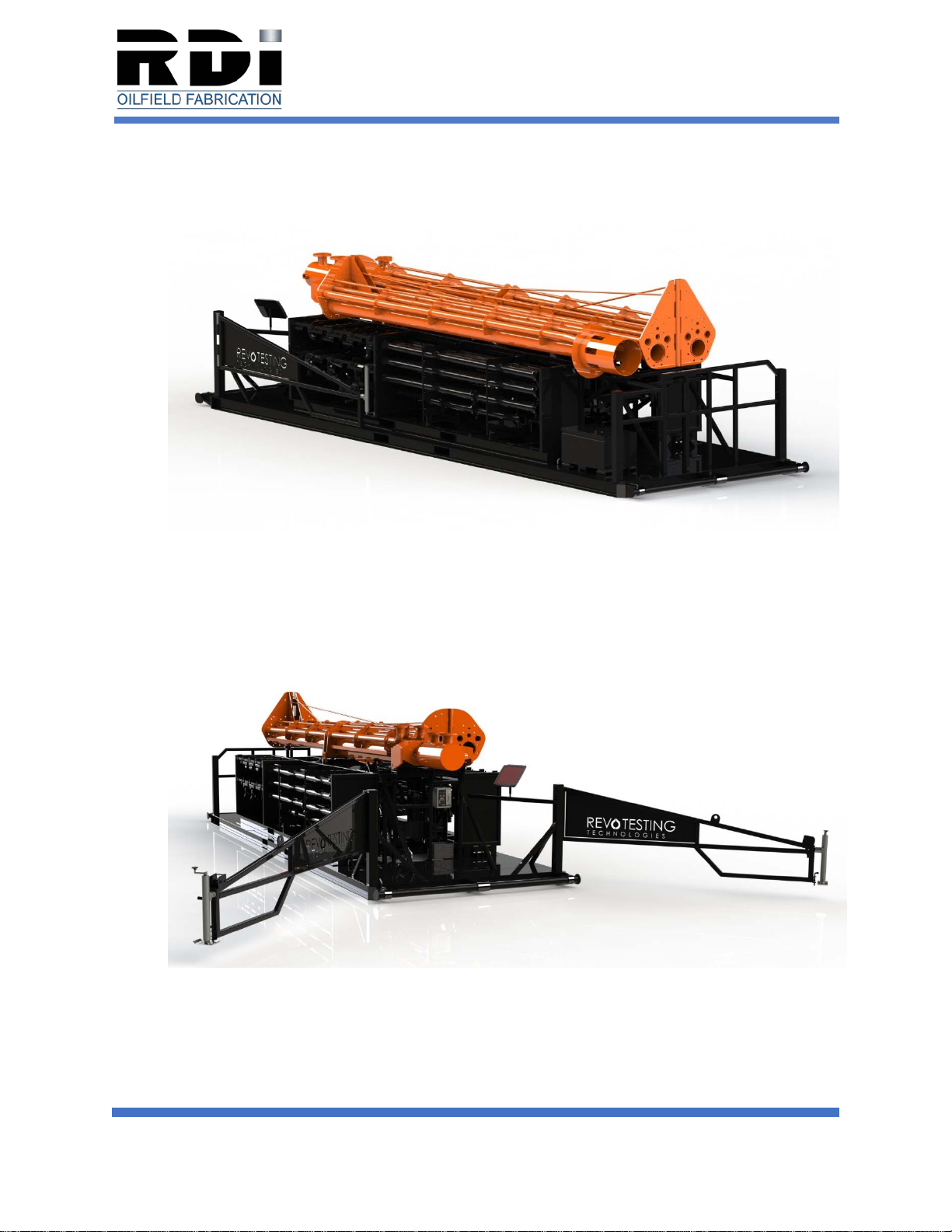
Prior to towing or moving the skid, insert and double-check that all bolt locking
mechanisms are installed to secure the flare stack, outriggers and jacks. Jacks need to
be perpendicular to the trailer frame before travel. Outriggers need to be in closed
position before travel.
Ensure that safety pin at headache rack for flare pipe ins pinned during unpacking and
unpinned during lifting to assist with side torque.
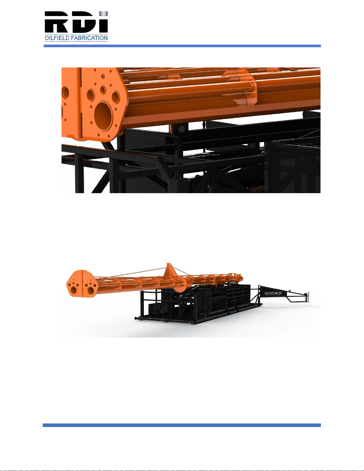
Before raising or lowering the stack, the REMOVABLE SKIDS MUST BE FULLY
LOADED AND PINNED INTO PLACE on the main skid.

860 FLARE SKID
INSTALLATION AND OPERATION
7
STANDARD OPERATING PROCEEDURE – UNPACK AND RAISE
1. Skid will be in packed position (Figure 2).
Figure 2 – Packed Position
2. Swing outriggers outward from the skid until locking pin can be inserted. (Figure
3) Outriggers should be 135° from closed position.
3. Rotate and lock all jacks into downward position.
4. Lower all jacks and level the skid.
Figure 3 – Outriggers in Open Position

860 FLARE SKID
INSTALLATION AND OPERATION
8
5. Remove the bolt that secures the lower stack to the frame. (Figure 4)
Figure 4 – Bolt Location
6. Raise the stack approximately 6”.
7. Swing middle and upper sections of the stack out together. Bolt flanges together.
Torque bolts to 376 ft lbs.
Figure 5 – Middle and Upper Stacks Open

860 FLARE SKID
INSTALLATION AND OPERATION
9
8. Remove the bolt restraints holding the upper stack to the middle stack. (Figure
6)
Figure 6 – Stack Open
9. Swing upper stack into open position and bolt flanges together (Figure 7).
Torque bolts to 376 ft lbs.
Figure 7 – Stack Fully Open

860 FLARE SKID
INSTALLATION AND OPERATION
10
10.Attach the guy wires. Make sure winches are in free roll setting. (Figure 8)
Figure 8 – Tie Cables
11.Connect 12VDC jumper cables to a fully charged battery. (Diesel equipment with
2 batteries is strongly recommended.)
12.Turn main power disconnect from “OFF” position (Figure 9) to “ON” position
(Figure 10).
Figure 9 – “OFF” Position Figure 10 – “ON” Position
13.Raise stack. Once the stack has started to raise, DO NOT release button until
stack is fully erect (Figure 11).
14.Tighten guy wires cables with winch.

860 FLARE SKID
INSTALLATION AND OPERATION
11
Figure 11 – Stack Fully Erected
15.Bolt scrubber ears to saddle ears (Figure 12). Torque bolts to 376 ft lbs.
Figure 12 – Scrubber Ear Bolts

860 FLARE SKID
INSTALLATION AND OPERATION
12
SOLAR PANEL CONNECTION
THE FOLLOWING STEPS FOR ACL SYSTEM MUST BE COMPLETED ONLY AFTER
THE JUMPER CABLES HAVE BEEN REMOVED FROM THE HYDRAULIC PUMP.
1. Remove the solar panel from the storage box.
2. Adjust solar panel to 45 degrees. (Center mark on bracket.) Face panel due
south.
3. Plug solar panel chord connector into battery box female and tighten.
4. Connect necessary ground and hot wires.
REMOVAL AND STORAGE PROCEDURE
THE FOLLOWING STEPS ARE TO BE PERFORMED BEFORE THE FLARE STACK
IS LOWERED AND STOWED.
1. Verify the valve at propane tank is closed.
2. Relieve pressure by opening bypass valve to pilot gas line and verify that the
pressure gauge reads 0 (zero) PSI.
3. Unplug solar panel chord from battery box. Place protective cap on cable end.
4. Remove solar panel mounting bracket and store in its box.
5. Verify that the battery selector switch is in the “OFF” position.
PACK / LOWER FLARE IGNITER
1. Place FULLY LOADED removable skids on main skid and pin into place.
2. Remove bolts from the scrubber and saddle ears.
3. Loosen the guy wires.
4. Press the down arrow button and run full throttle. DO NOT RELEASE THE
BUTTON AT ANY TIME DURING THE LOWERING PROCESS.
5. Detach the guy wires from the stack.
6. Remove bolts from upper/mid stack flange and fold to the mid stack.
7. Remove the bolts from mid-lower stack flange and fold back onto the skid.
8. Install the bolt/pin restraints on the lower/upper stack to the skid.

860 FLARE SKID
INSTALLATION AND OPERATION
13
TROUBLESHOOTING GUIDE
In the event of an ignitor malfunction while gas is being released into the tube, shut off
gas supply and wait 5 minutes for any trapped gas to purge. Gas build-up can cause
damage to the unit, injury or death if it is ignited. Once the purge is complete, turn on
gas and go through the basic operational procedures outlined in “Standard Operating
Procedure”.
If the flare stack will not raise completely up and line up with the pinning position, use
the guide wires to take slack off the flare stack. You then should be able to secure the
pin.
If the battery drains of power, it is probably due to lack of charge. Ensure that the solar
panel is connected and facing south. This will ensure that the battery holds a charge at
all times.

860 FLARE SKID
INSTALLATION AND OPERATION
14
MAINTENANCE REQUIREMENTS
NOTICE: The flare skid and all components should be completely expected prior to
each use. Skid should be inspected for cracks, damage and wear and tear prior to
being put into service.
DISCONNECT all electrical and gas supply sources prior to servicing unit. Failure to do
so may result in personal injury or death from electrical shock.
Grease zerks should be greased as needed and at a minimum of every 3 months.
Rubber gasket in hinged area should be regularly inspected and replaced when
noticeable wear and tear is evident.
Ceramic insulators should be replaced if cracked or show any sign of damage.

860 FLARE SKID
INSTALLATION AND OPERATION
15
Flare trailer stacks to conform to 40 CFR-60.18
(c)(2) Flares shall be operated with a flame present at all times, as determined by the
methods specified in paragraph (f).
(c)(3) An owner/operator has the choice of adhering to either the heat content
specifications in paragraph (c)(3)(iii) of this section and the maximum tip velocity
specifications in paragraph (c)(4) of this section, or adhering to the requirements in
paragraph (c)(3)(i) of this section.
(i)(A) Flares shall be used that have a diameter of 3 inches or greater, are non-
assisted, have a hydrogen content of 8.0 percent (by volume) or greater and are
designed for and operated with and exit velocity of less than 37.2 m/sec (122 ft/sec) and
less than the velocity Vmax as determined by the following equation:
Vmax = (XH2-K1)*K2
Where:
Vmax = Maximum permitted velocity, m/sec.
K1= Constant 6.0 volume-percent hydrogen.
K2= Constant 3.9 (m/sec) / volume-percent hydrogen
XH2 = The volume-percent of hydrogen, on a wet basis, as calculated by using
the American Society for Testing and Materials (ASTM) Method D1946-77.
(Incorporated by reference as specified in §60.17).
(B) The actual exit velocity of a flare shall be determined by the method specified in
paragraph (f)(4) of this section.
(ii) Flares shall be used only with the net heating value of the gas being combusted
11.2 MJ/scm (300 btu/scf) or greater if the flare is steam-assisted; or with the net
heating value of the gas being combusted being 7.45 MJ/scm (200 btu/scf) pr greater of
the flare is non-assisted. The net heating value of the gas being combusted shall be
determined by the methods specified in paragraph (f)(3) of this section.
(4)(i) Steam-steam assisted and non-assisted flares shall be designed for
and operated with an exit velocity, as determined by the methods
specified in paragraph (f)(4) of this section, less than 18.3 m/sec (60
ft/sec), except as provided in paragraphs (c)(4)(ii) and (iii) of this section.

860 FLARE SKID
INSTALLATION AND OPERATION
16
(ii) Steam-assisted and non-assisted flares designed for and operated
with an exit velocity, as determined by the methods specified in paragraph
(f)(4) equal to or greater than 18.3 m/sec (60 ft/sec) but less than 122
m/sec (400 ft/sec) are allowed if the net heating value of the gas being
combusted is greater than 37.3 MJ/scm (1000 btu/scf).
(iii) Steam-assisted and non-assisted flares designed for and operated
with an exit velocity, as determined by the methods specified in paragraph
(f)(4), less than the velocity Vmax as determined by the method specified in
paragraph (f)(5) and less than 122 m/sec a(400 ft/sec) are allowed.
(5) Air-assisted flares shall be designed and operated with an exit velocity
less than the velocity Vmax as determined by the method specified in
paragraph (f)(6).
(6) Flares used to comply with this section shall be steam-assisted, air-
assisted or non-assisted.
(d) Owners or operators of the flares used to comply with the provisions
of this subpart shall monitor these control devices to ensure that they are
operated and maintained in conformance with their designs. Applicable
subparts will provide provisions stating how owners or operators of flares
shall monitor these control devices.
(e) Flares used to comply with provisions of this subpart shall be operated
at all times when emissions may be vented to them.
(f)(1) Method 22 of Appendix A to this part shall be used to determine the
compliance of flares with the visible emission provisions of this subpart.
The observation period is 2 hours and shall be used according to Method
22.
(2) The presence of a flare pilot flame shall be monitored using a
thermocouple or any other equivalent device to detect the presence of a
flame.
(3) The net heating value of the gas being combusted in a flare shall be
calculated using the following equation: HT= K ∑
=0 CiHi

860 FLARE SKID
INSTALLATION AND OPERATION
17
(f)(4) The actual exit velocity of a flare shall be determined by dividing the volumetric
flow rate (in units of standard temperature and pressure) as determined by Reference
Methods 2, 2A, 2C or 2D as appropriate; by the unobstructed (free) cross sectional area
of the flare tip.
(f)(5) The maximum permitted velocity, Vmax for flares complying with paragraph
(c)(4)(iii) shall be defined by the following equation: Log10(Vmax) = (HT28.8)/31.7
Where:
Vmax = Maximum permitted velocity, m/sec
28.8 = Constant
31.7 = Constant
HT= The net heating value as determined in paragraph (f)(3).
(B) The actual exit velocity of a flare shall be determined by the method specified in
paragraph (f)(4) of this section.

860 FLARE SKID
INSTALLATION AND OPERATION
18
860 Flare Skid
Non-assisted Flare Unit
40 CFR 60.18 Compliance Letter
Following (c)(3)(i)(a) under CFR 60.18
In order to comply with (c)(3)(i), assuming the maximum exit velocity to be 122 ft/sec and flare
tip to be 12” pipe, the maximum flow rate allowed would be 8,275,000 cubic feet per day. Since
the composition of the flare gas will differ on a case by case basis, the maximum allowable flow
rate can be further constrained by the maximum velocity equation given in paragraph
(c)(3)(i)(A).
Q = (velocity)(area) = 122 ft (.785 sq. ft.) / sec = 95.77 cu ft/sec = 8,275,000 cu ft/day
Maximum Flow Rate
The other option is to comply with paragraph (c)(3)(ii) and paragraph (c)(4)
The Vmax and flow rate calculation for gas with a net heating value of 7.45 MJ/scm (200 btu/scf)
would be: (Minimum Flare-able Gas)
Vmax = 7.45(28.8)/(31.7) = 6.77 m/sec = 22.21 ft/sec
Q = 22.21 ft(.785 sq. ft.)/sec = 17.43 cu ft/sec = 1,506,000 cu ft/sec Maximum Flow Rate
For a net heating value of 37.3 MJ/scm (1000 btu/scf) the calculation would be (Natural Gas
Assumption):
Vmax = 37.3(28.8)/31.7 = 33.89 m/sec = 111.2 ft/sec
Q = 111.2 ft (.785 sq ft)/sec = 87.29 cu ft/sec = 7,542,000 cu ft/day Maximum Flow rate
To ensure compliance across all gas compositions with the standard, we would need to know
either:
1. The volume-percent hydrogen of the flare gas to calculate Vmax per paragraph (c)(3)(i), or
2. The net heating value of the gas to calculate Vmax per paragraph (f)(5).
Tyson A. Smith
RDI Oilfield Fabrication Operations Manager

860 FLARE SKID
INSTALLATION AND OPERATION
19
Based on values given using the following textbook:
Paraphrasing from the “John Zink Hamworthy Combustion Handbook, 2nd Edition:
Volume 3, Section 11.5 Flare Combustion Products”
11.5.1 Reaction Efficiency
The terms combustion efficiency and destruction efficiency have frequently and
mistakenly been considered synonymous. In fact, these two concepts are quite
different. A flare operating with a combustion efficiency of 98% can achieve a
destruction efficiency in excess of 99.5%
11.5.1.1 Definition of Destruction and Combustion Efficiency
Destruction efficiency is a measure of how much the original hydrocarbon is destroyed,
that is broken down into non-hydrocarbon forms, specifically carbon monoxide (CO),
carbon dioxide (CO2) and water vapor (H2O). The destruction efficiency can be
calculated by a carbon balance equation as follows:
%DE = [(CO2 + CO)/(CO2 + CO + UHC)] x 100
The %DE is the percent destruction efficiency, and UHC refers to unburned
hydrocarbons in the plume at the end of the flare flame. Notice that if no UHC’s escape
the flame the DE is 100%.
Combustion efficiency is a measure if how much of the original hydrocarbon burns
completely to CO2and water vapor. The combustion efficiency carbon balance
equation would be:
%CE = [CO2/(CO + UHC)] x 100
Notice that even if no UHC’s escape the flame, the combustion efficiency can be less
than 100% because CO represents incomplete combustion. It is evident from the
equations that the combustion efficiency will always be less than or equal to the
destruction efficiency.
11.5.1.2 Technical Review of Industrial Flare Combustion Efficiency
….the US EPA ruled that a flare can achieve a combustion efficiency of 98% or greater
if the exit velocity of the organic waste stream, at the flare tip, is within the following
limits:

860 FLARE SKID
INSTALLATION AND OPERATION
20
1) Non-assisted and steam-assisted flares
a. If 200 btu/scf < LHV < 300 btu/scf
Vmax(ft/s) = 60 x [(T+460)/528]
b. If 300 btu/scf <LHV < 1000 btu/scf
Vmax(ft/s) = antilog10[(LHV + 1209.6/849.1] x [T + 460/528]
c. If LHV > 1000 btu/scf
Vmax(ft/s) = 400 [T+460/528] where T = °F and LHV @ standard cond, 1
atm, 68°F
11.5.2 Emissions
….the US EPA AP-42 Chapter 13.5 guidance document suggests that a properly
operated flare, with a combustion efficiency of 98% or greater will emit UHC, CO and
NOXat the following rates:
- UHC: 0.14 lb / MMbtu fired
- CO: 0.37 lb / MMbtu fired
- NOX: 0.068 lb / MMbtu fired
When it comes down to it, all we can do is go with 60.18 to assure a 98% combustion
efficiency. Since prove well samples are over 1000 btu/scf we can use this section of
the code.
(ii) Steam-assisted and non-assisted flares designed for and operated with an
exit velocity as determined by the methods specified in paragraph (f)(4), equal to or
greater than 18.3 m/sec (60 ft/sec) but less than 122 m/sec (400 ft/sec) are allowed if
the net heating value of the gas being combusted is greater than 37.3 MJ/scm (1000
btu/scf)
(f)(4) The actual exit velocity of a flare shall be determined by dividing the volumetric
flow rate (in units of standard temperature and pressure), as determined by Reference
Methods 2, 2A, 2C or 2D as appropriate; by the unobstructed (free) cross sectional area
of the flare tip.
This gives us a minimum exit velocity of 60 ft/sec and a maximum of 400 ft/sec.
Volumetric flow rate = exit velocity x flare tip cross sectional area. Assuming we would
use the 12” pipe for the flare tip area:
Table of contents
Other RDI Construction Equipment manuals
Popular Construction Equipment manuals by other brands

FMG
FMG KHL120 Operator's manual

MetalTech
MetalTech JOBSITE I-IDS1830 OPERATIONAL SAFETY AND ASSEMBLY INSTRUCTIONS

Maeda
Maeda CC1485S-1 Operation manuals

PFT
PFT RITMO XL operating instructions

Hitachi
Hitachi VB 16Y Handling instructions

Wolff Finnhaus
Wolff Finnhaus WOLFF 7032.12 clear technical information

Tru-Turf
Tru-Turf RE50 owner's manual

MetalTech
MetalTech AL-Q0108 OPERATIONAL SAFETY AND ASSEMBLY INSTRUCTIONS

HIAB
HIAB 160TM Operating manual / spare parts list

Altrad Belle
Altrad Belle TDX 650 Operator's manual

Clarke
Clarke CHT264 Operation & maintenance instructions

Escalo
Escalo WORKMAX I instruction manual