Model HR-UDC1
Universal Digital Audio Converter
TYPICAL PERFORMANCE
Inputs (4): 110 ΩAES/EBU XLR, transformer isolated; S/PDIF optical; 75 ΩS/PDIF
coaxial phono jack; 75 ΩAES-3ID BNC
Outputs (4): 110 ΩAES/EBU XLR, transformer isolated; S/PDIF optical; 75 ΩS/PDIF
coaxial phono jack; 75 ΩAES-3ID BNC
Selector: Rear-panel output format selector
Sample Rate: 32 kHz to 192 kHz
Resolution: 16 to 24 bits
Indicators (12): POWER LED; INPUT FORMAT LEDs (2); Sample Rate LEDs (9)
Standards: AES3-2003, IEC60958
Power Requirement: 24 to 33 Vdc @ 50 mA, Ground-referenced
Mounting: Rack-mount using optional rack adapters such as HR-RA2; or operate free-standing
(feet included)
Dimensions: Height: 1.7 in 4.3 cm
Length: 8.6 in 20.6 cm
Depth: 4.59 in 11.66 cm
Installation/Operation
EN55103-1 E1-E5; EN55103-2 E1-E4
Typical Performance reflects product at publication time
exclusive of EMC data, if any, supplied with product.
Specifications are subject to change without notice.
891-3260A
Radio Design Labs Technical Support Centers
U.S.A. (800) 933-1780, (928) 778-3554; Fax: (928) 778-3506
Europe [NH Amsterdam] (++31) 20-6238 983; Fax: (++31) 20-6225-287
HALF-RACK SERIES
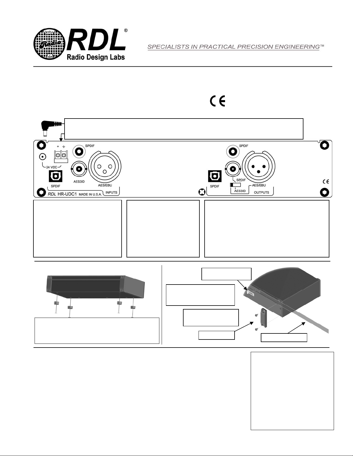
Connect one digital audio
source to the appropriate
input jack:
S/PDIF OPTICAL,
S/PDIF COAXIAL,
AES-3ID or
AES/EBU
Connect one digital
audio cable to the
appropriate output
jack:
S/PDIF OPTICAL,
S/PDIF COAXIAL,
AES-3ID or
AES/EBU
Set the output format switch to the
desired format:
S/PDIF (enables the COAXIAL and OPTICAL jacks),
AES-3ID (BNC jack) or
AES/EBU (XLR jack)
Connect 24 Vdc to either of the power inputs: DC Jack or Detachable terminal block
3. Place Adhesive Label over
Laminate in Track
The functions of this product can be
conveniently and professionally labeled
with a hand-held label printer equipped
with ¼” wide clear label tape.
For free-standing operation, use the four provided machine screws to
mount the feet to the bottom of the module as shown.
OR
Use the four provided machine screws to secure the module to an
optional RDL mount, such as an HR-RA2 Rack Adapter.
4. Slide Lens back in position,
covering the clear adhesive
labels. Replace the End Cap.
1. Remove End Ca
2. Slide Lens Out of Track
LABELING
MOUNTING
NOTE: This equipment has been tested and found to
comply with the limits for a Class B digital device, pursuant
to part 15 of the FCC Rule. These limits are designed to
provide reasonable protection against harmful interference
in a residential installation. The equipment generates,
uses and can radiate radio frequency energy and, if not
installed and used in accordance with the instructions,
may cause harmful interference to radio communications.
However, there is no guarantee that interference will not
occur in a particular installation. If this equipment does
cause harmful interference to radio or television reception,
which can be determined by turning the equipment off an
on, the user is encouraged to try to correct the
interference by one or more of the following measures:
•Reorient or relocate the receiving antenna
•Increase the separation between the equipment
and receiver
•Connect the equipment into an outlet on a circuit
different from that which the receiver is
connected.
•Consult the dealer or an experienced radio/TV
technician for help.


