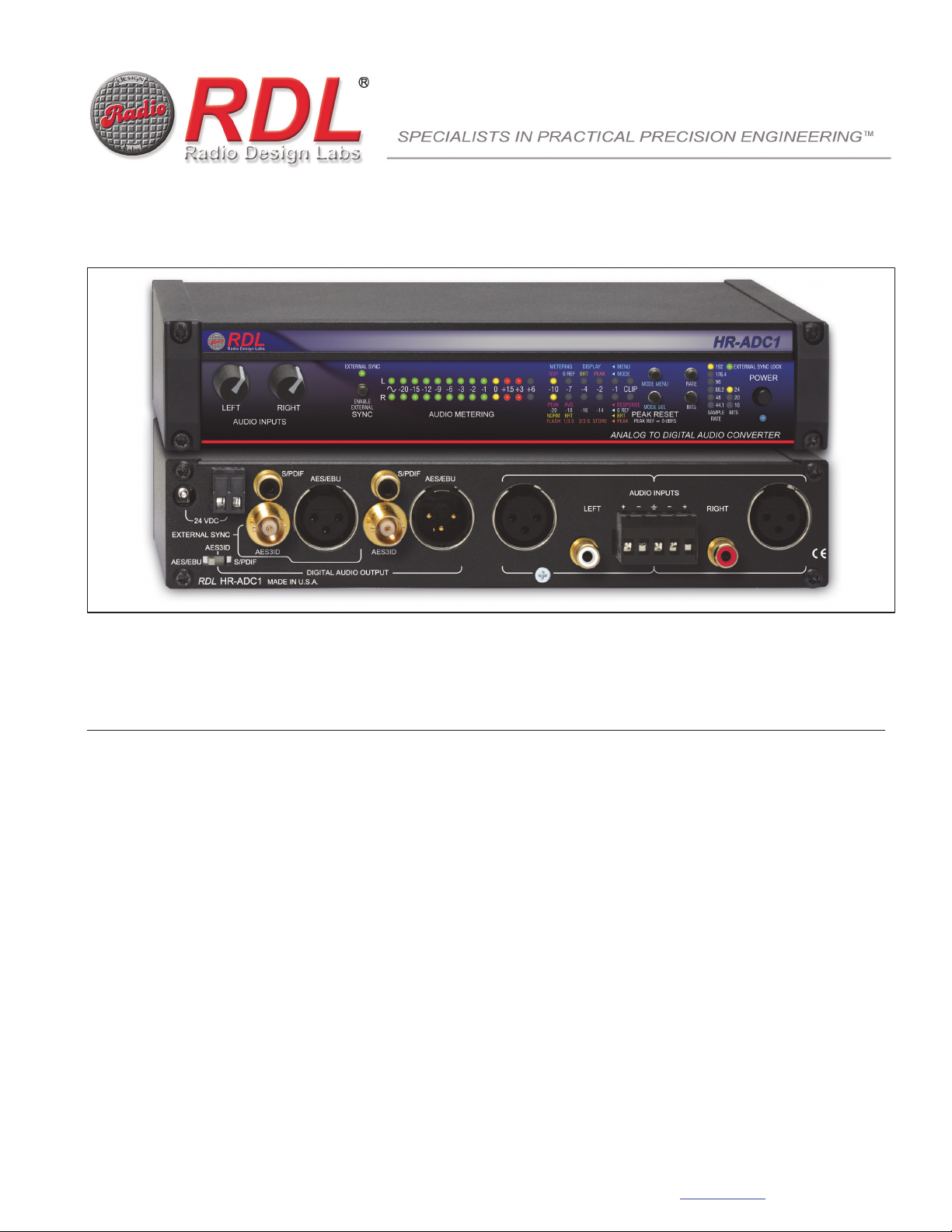
manuals.online logo
Brands
  1. Home
  2. •
  3. Brands
  4. •
  5. RDL
  6. •
  7. Media Converter
  8. •
  9. RDL HALF-RACK Series User manual

RDL HALF-RACK Series User manual

Model HR-ADC1
Analog to Digital Audio Converter

Broadcast Quality Analog to Digital Audio Conversion

Inputs: Balanced and Unbalanced Stereo Audio

Output: AES/EBU, Coaxial S/PDIF, AES-3ID

External Sync Inputs: AES/EBU, Coaxial S/PDIF, AES-3ID

Adjustable Audio Input Gain Trim

Peak or Average Ballistic Metering with Selectable 0 dB Reference

Peak Metering with Selectable Hold or Peak Store Modes

Operation Up to 24 bits, 192 kHz

Selectable Internally Generated Sample Rate and Bit Depth

Front-Panel External Sync Enable Selector and Indicator

Sample Rate, Bit Depth, External Sync Lock Indicators

Transformer Isolated AES/EBU Output
The HR-ADC1 is an RDL HALF-RACK product, featuring an all metal chassis and the advanced circuitry for which RDL products are known. HALF-RACKs may be operated free-standing using
the included feet or may be conveniently rack mounted using available rack-mount adapters.
APPLICATION: The HR-ADC1 is a broadcast quality A/D converter that provides exceptional audio accuracy and clarity with any audio source or style.
Superior analog performance fine tuned through audiophile listening practices produces very low distortion (0.0006%), exceedingly low noise (-135 dB) and
remarkably flat frequency response (+/- 0.05 dB). This performance is coupled with unparalleled metering flexibility and programmability with average
mastering level monitoring and peak value storage. With external sync capability plus front-panel settings up to 24 bits and up to 192 kHz sample rate, the
HR-ADC1 is the single instrument needed for A/D conversion in demanding applications.
The HR-ADC1 accepts balanced +4 dBu or unbalanced -10 dBV stereo audio through rear-panel XLR or RCA jacks or through a detachable terminal block.
An external AES/EBU, AES-3ID or S/PDIF sync source may be connected through a rear-panel XLR, RCA or BNC jack. Digital audio outputs are provided in
AES/EBU, AES-3ID or S/PDIF formats. The rear-panel switch-selected output format is available on the corresponding XLR, RCA or BNC jack.
Front panel LEFT and RIGHT controls permit input gain adjustment to produce the desired average signal level for the digital conversion. The zero decibel
(0 dB) reference level of the audio metering string may be set to -14, -16, -18 or -20 dBFS. The meter may also be set to display peak or VU average audio
levels. Audio peaks between -10 dBFS and 0 dBFS (clipping) are displayed separately to the right of the standard audio level meter. The peak display may
be set to either flash or store the peak values. Flash duration settings provide for instantaneous, 1/3 second hold or 2/3 second hold. If the peak display is
set to STORE then the highest peak recorded remains displayed until the PEAK RESET button is pushed.
The HR-ADC1 provides rear-panel inputs for an external sync source. If valid external sync is connected, the EXTERNAL SYNC LOCK LED illuminates.
The front-panel SYNC button sets the converter to synchronize to the external source. When external sync is active, the EXTERNAL SYNC LED illuminates.
If external sync is selected but unavailable, the EXTERNAL SYNC LED flashes. When external sync is not used, the HR-ADC1 converts at the sample rate
selected using the front-panel RATE button. The number of BITS is user-selectable on the front panel. The peak LEDs double as the programming
indicators during setup. The MODE MENU has four selection categories: METERING RSP (response) allows selection of PEAK or AVG (average) for the
main audio metering display; METERING 0 REF allows setting the meter scaling to -14, -16, -18 or -20 dBFS for a reading of 0 dB; DISPLAY BRT
(brightness) allows the LED display brightness to be set to NORM or BRT (bright) depending on the ambient light; DISPLAY PEAK allows the peak LED
string to be set to FLASH, hold the peak reading 1/3 second, hold the peak reading 2/3 second, or STORE the maximum peak reading. Programming
selections are automatically stored after five seconds and are retained in memory when the HR-ADC1 is re-powered.
The HR-ADC1 is powered from 24 Vdc, which may be connected through the detachable terminal block or through the dc power jack. A front-panel power
switch is provided.
HALF-RACK SERIES
RDL 659 6th St. Prescott, AZ., USA 86301 (928) 443-9391 FAX (928) 443-9392 www.rdlnet.com
Model HR-ADC1
Analog to Digital Audio Converter
TYPICAL PERFORMANCE
Audio Inputs (5): Balanced (2): 30 kXLR (Left and Right); Balanced terminal block; Unbalanced (2): 30 kRCA jacks (Left and Right)
Input Level: Left and Right front-panel user controls, Balanced: +4 dBu nominal; +2 dBu to +26 dBu (for 0 dBFS)
ubalanced: -10 dBV nominal; -11 dBV to +11 dBV (for 0 dBFS)
External Sync Inputs (3): 110 AES/EBU XLR, transformer isolated; 75 S/PDIF coaxial phono jack; 75 AES-3ID BNC
(automatically selected)
Outputs (3): 110 AES/EBU XLR, transformer isolated; 75 S/PDIF coaxial phono jack; 75 AES-3ID BNC
rear-panel switch selectable)
Sample Rates: 44.1 kHz, 48 kHz, 88.2 kHz, 96 kHz, 176.4 kHz, 192 kHz
(internal, front-panel selectable; external sync rate is displayed if external sync is enabled)
Resolution: 16, 20 or 24 bits (front-panel selectable)
Frequency Response: 10 Hz to 20 kHz (+/- 0.125 dB); 20 Hz to 20 kHz (+/- 0.05 dB)
THD+N: < -105 dBFS (0.0006%, 20 Hz to 20 KHz, internal sample rate); <-100 dBFS (0.001%, 20 Hz to 20 KHz, external sync)
Crosstalk: < -115 dB (50 to 60 Hz); < -105 dB (15 kHz)
Residual Noise: < -135 dB (10 Hz to 20 kHz)
Dynamic Range: > 114 dB (resolution 24-bit unweighted)
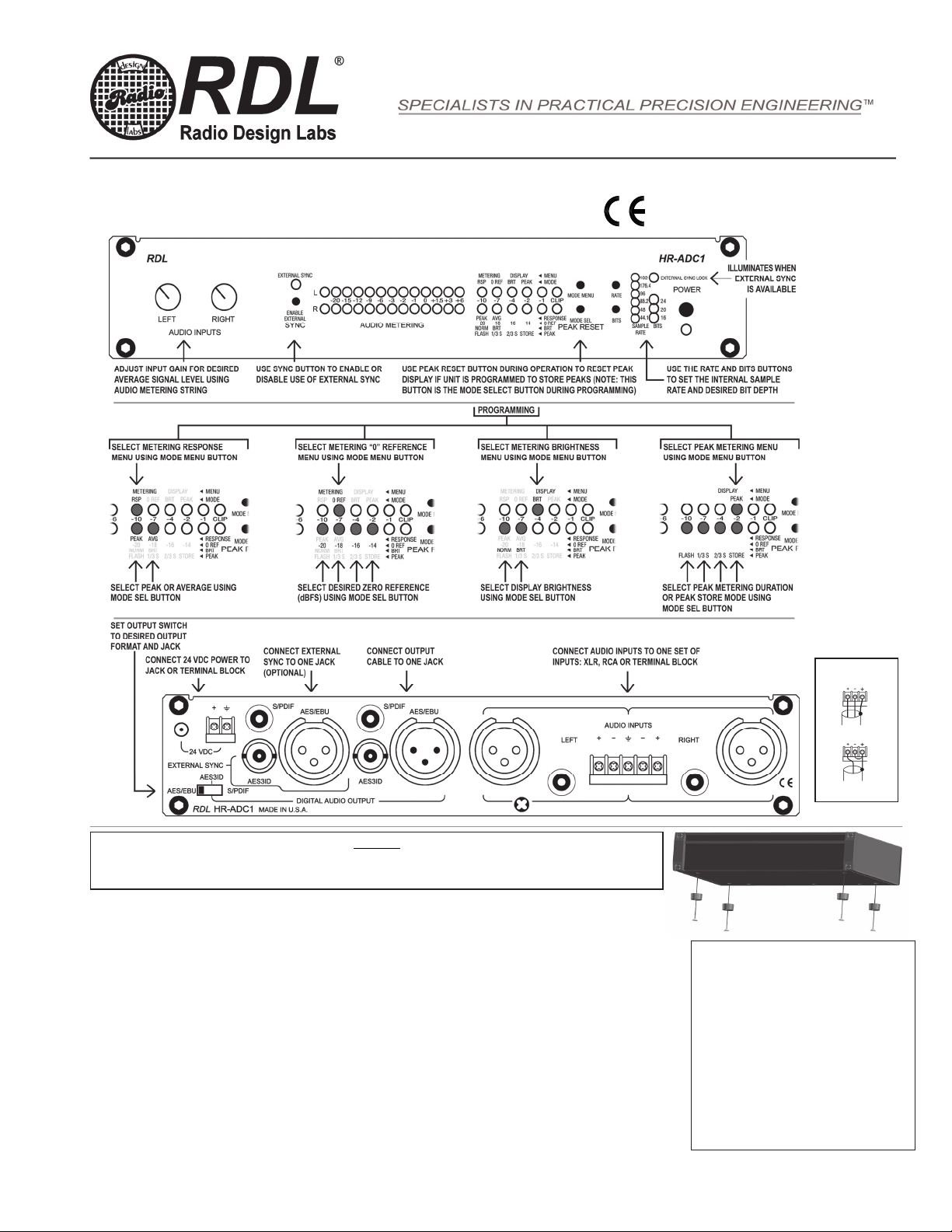
Programmable Features Menus (4): Metering Ballistic (2): Peak or Average; Meter Reference (4): -20, -18, -16, -14 dBFS;
Peak hold (4): Momentary flash, 1/3 s., 2/3 s., store; Display intensity (2): Normal or bright
Indicators (49): POWER LED
EXTERNAL SYNC LOCK LED (locked to valid input signal)
SAMPLE RATE (6): 44.1 kHz, 48 kHz, 88.2 kHz, 96 kHz, 176.4 kHz, 192 kHz; BITS (3): 16, 20, 24
AUDIO METERING (26): Audio present, -20, -15, -12, -9, -6, -3, -2, -1, 0, +1.5, +3, +6 dB
PEAK METERING (12): -10, -7, -4, -2, -1 dBFS, CLIP
Measurement Reference: 0 dBFS
(+22 dBu = 0 dBFS @ 1 kHz, Operating level: -2 dBFS, 24 bits, 192 kHz internal sample rate unless otherwise noted)
Standards: AES3-2003, IEC60958
Power Requirement: 24 to 33 Vdc @ 300 mA, Ground-referenced
Mounting: Rack-mount using optional rack adapters such as HR-RA2; or operate free-standing (feet included)
Dimensions: Height: 1.7 in, 4.3 cm; Length: 8.6 in, 20.6 cm; Depth: 4.59 in, 11.66 cm
Installation/Operation
Declaration of Conformity available from rdlnet.com.
Sole EMC specifications provided on product package.
Specifications are subject to change without notice.
891-3310C
Radio Design Labs Technical Support Centers
U.S.A. (800) 933-1780, (928) 778-3554; Fax: (928) 778-3506
Europe [NH Amsterdam] (++31) 20-6238 983; Fax: (++31) 20-6225-287
HALF-RACK
MOUNTING
For free-standing operation, use the four provided machine screws to mount the feet to the bottom of the module as shown, OR
Use the four provided machine screws to secure the module to an optional RDL mount, such as an HR-RA2 Rack Adapter.
TERMINAL
BLOCK WIRING
BALANCED
UNBALANCED
NOTE: This equipment has been tested and found to
comply with the limits for a Class B digital device, pursuant
to part 15 of the FCC Rule. These limits are designed to
provide reasonable protection against harmful interference
in a residential installation. The equipment generates,
uses and can radiate radio frequency energy and, if not
installed and used in accordance with the instructions,
may cause harmful interference to radio communications.
However, there is no guarantee that interference will not
occur in a particular installation. If this equipment does
cause harmful interference to radio or television reception,
which can be determined by turning the equipment off an
on, the user is encouraged to try to correct the
interference by one or more of the following measures:
Reorient or relocate the receiving antenna
Increase the separation between the equipment
and receiver
Connect the equipment into an outlet on a circuit
different from that which the receiver is
connected.
Consult the dealer or an experienced radio/TV
technician for hel
p
.

This manual suits for next models

1

Other RDL Media Converter manuals

RDL RLC-10R User manual

RDL

RDL RLC-10R User manual

RDL Half-Rack Series User manual

RDL

RDL Half-Rack Series User manual

RDL HALF-RACK Series User manual

RDL

RDL HALF-RACK Series User manual

RDL HR-DDA4 User manual

RDL

RDL HR-DDA4 User manual

RDL EZ-AFC2 User manual

RDL

RDL EZ-AFC2 User manual

RDL Half-Rack Series Guide

RDL

RDL Half-Rack Series Guide

RDL HALF-RACK Series Guide

RDL

RDL HALF-RACK Series Guide

RDL TX-LC2 Owner's manual

RDL

RDL TX-LC2 Owner's manual

Popular Media Converter manuals by other brands

ADF Web HD67941-B2-Y user manual

ADF Web

ADF Web HD67941-B2-Y user manual

Connective Peripherals ES-U Series manual

Connective Peripherals

Connective Peripherals ES-U Series manual

GoMax Electronics MX-5022 user manual

GoMax Electronics

GoMax Electronics MX-5022 user manual

ADF Web EnOcean user manual

ADF Web

ADF Web EnOcean user manual

Westermo MCI-211G Quick installation guide

Westermo

Westermo MCI-211G Quick installation guide

ZyCast HDME-804 User guide and installation manual

ZyCast

ZyCast HDME-804 User guide and installation manual

Baumer HOG 28 Installation and operating instructions

Baumer

Baumer HOG 28 Installation and operating instructions

Honeywell SiX Series installation guide

Honeywell

Honeywell SiX Series installation guide

Audizio Prato instruction manual

Audizio

Audizio Prato instruction manual

iM3 ultra-S Instructions for use

iM3

iM3 ultra-S Instructions for use

Cypress CP-255H Operation manual

Cypress

Cypress CP-255H Operation manual

RGBlink MSP 200PRO user manual

RGBlink

RGBlink MSP 200PRO user manual

Radial Engineering Decoder user guide

Radial Engineering

Radial Engineering Decoder user guide

StarTech.com HDMI2HDMI instruction manual

StarTech.com

StarTech.com HDMI2HDMI instruction manual

Tektronix SD-48 instruction manual

Tektronix

Tektronix SD-48 instruction manual

US Digital E4T Assembly instructions

US Digital

US Digital E4T Assembly instructions

ISON IS-DG102-F Quick installation quide

ISON

ISON IS-DG102-F Quick installation quide

ELPRO CONVI104R user manual

ELPRO

ELPRO CONVI104R user manual

manuals.online logo
manuals.online logoBrands
  • About & Mission
  • Contact us
  • Privacy Policy
  • Terms and Conditions

Copyright 2025 Manuals.Online. All Rights Reserved.