RDS Technology Weighlog 200 User manual

Weighlog 200
On-
Board
Weighing System
Calibration and Operation
Software Reference WZ305-
005 rev.07
Electro-Magnetic Compatibility (EMC)
This prod ct complies with Co ncil Directive 2004/108/E
C
when installed and sed in accordance with the relevant
instr ctions.
Service and echnical Support
PLEASE CONTACT YOUR NEAREST DISTRIBUTOR
If nknown then fax: 44 (0) 1453 733322
© Copyright RDS Technology Ltd 2010
Doc ment n mber
S/DC/500-10-344 : Iss e 6.03 : 6/5/10
\UK344603.DOC
User Guide

CONTENTS
2
Contents
1. Overview_________________________________________4
Programming Modes..................................................................................................5
2The Control Switches _____________________________6
2.1
Display Units ....................................................................................................7
2.2
Machine req irements .....................................................................................7
2.3
Lifting proced re..............................................................................................8
3. Before Weighing__________________________________9
3.1
Select Channel................................................................................................9
3.2
Select the Weighing Mode...............................................................................9
Checking the Weighing Mode. .................................................................9
3.3
Check Zero Weight ........................................................................................10
3.4
Zero Weight (Set Tare)...................................................................................11
4Weighing ______________________________________ 12
4.1
Dynamic Weighing.........................................................................................12
4.2
Static weighing...............................................................................................12
4.3
Trailer Weighing .............................................................................................13
4.4
Incorrect Weight readings..............................................................................14
Adjusting a Weight reading in normal operating mode..................................1
4.5
Load Alarm.....................................................................................................15
4.6
Printing ...........................................................................................................15
Printing a Channel total (Channels 1 to 5) .....................................................15
Printing a Grand Total.....................................................................................15
Automatic Printing ..........................................................................................16
5Totals__________________________________________ 1
5.1
Reset Individ al S b-totals / Grand Total......................................................17
5.2
Display Time...................................................................................................17

CONTENTS
3
6Calibration _____________________________________ 18
6.1
Programme a N meric Setting...................................................................... 18
Entering a Negative Value.............................................................................. 18
6.2
CAL Mode 1 – Weight Calibration ................................................................. 19
6.2.1
Enter CAL Mode 1 ........................................................................... 21
6.2.2
Set Weighing Mode......................................................................... 21
6.2.3
Set Initial Cal. Factor ....................................................................... 21
6.2.
Weight Calibration Routine.............................................................. 22
(i)
Proportional Scaling Factor/Speed Compensation ............................ 22
(ii)
Set Cal. Factor (with a Test Load)....................................................... 23
6.2.5
Overload Alarm Setup ..................................................................... 2
6.3
CAL mode 2................................................................................................... 25
6.3.1
Enter CAL Mode 2 ........................................................................... 25
6.3.2
Speed Compensation (Channel 1).................................................. 25
6.3.3
Live Static (Channel 2) .................................................................... 26
6.3.
“REF” Button (Channel 3)................................................................ 27
6.3.5
Time / Date (Channel ) .................................................................. 27
6.3.6
Language (Channel 5) .................................................................... 27
6.3.7
Units (TOTAL Channel).................................................................... 28
6.4
CAL mode 3 (Print Set p) ............................................................................. 29
6. .1
Enter CAL Mode 3 ........................................................................... 29
6. .2
Set Print Mode (channel 1) ............................................................. 29
6. .3
Handshaking (Channel 2) ............................................................... 30
6. .
Edit Print Heading (Channel 3)........................................................ 30
6. .5
Cal Factor Adjustment (‘NUDGE’) ................................................... 30
Error message: "Prog".............................................................................................. 31
Error message: "Err" ................................................................................................. 31
Error Message: “CAL” “Err” ............................................................................. 31
Changing loading attachments................................................................................ 31
Diagnostic Mode ...................................................................................................... 33

OVERVIEW
4
1. Overview
The Weighlog 200 is intended for se on ind strial and agric lt ral loading
shovels, fore-end loaders, back-hoe loaders, (loader side only), tipping
trailers and tipping tr cks.
It meas res, displays and records the net weight lifted, normally based on
sensing the lift system hydra lic press re. Press re sensing is problematic
on certain types of eq ipment d e to the design of the hydra lic system. In
these instances strain sensing technology may be sed instead. The
Weighlog 200 also has lift speed compensation to improve acc racy when
weighing dynamically.
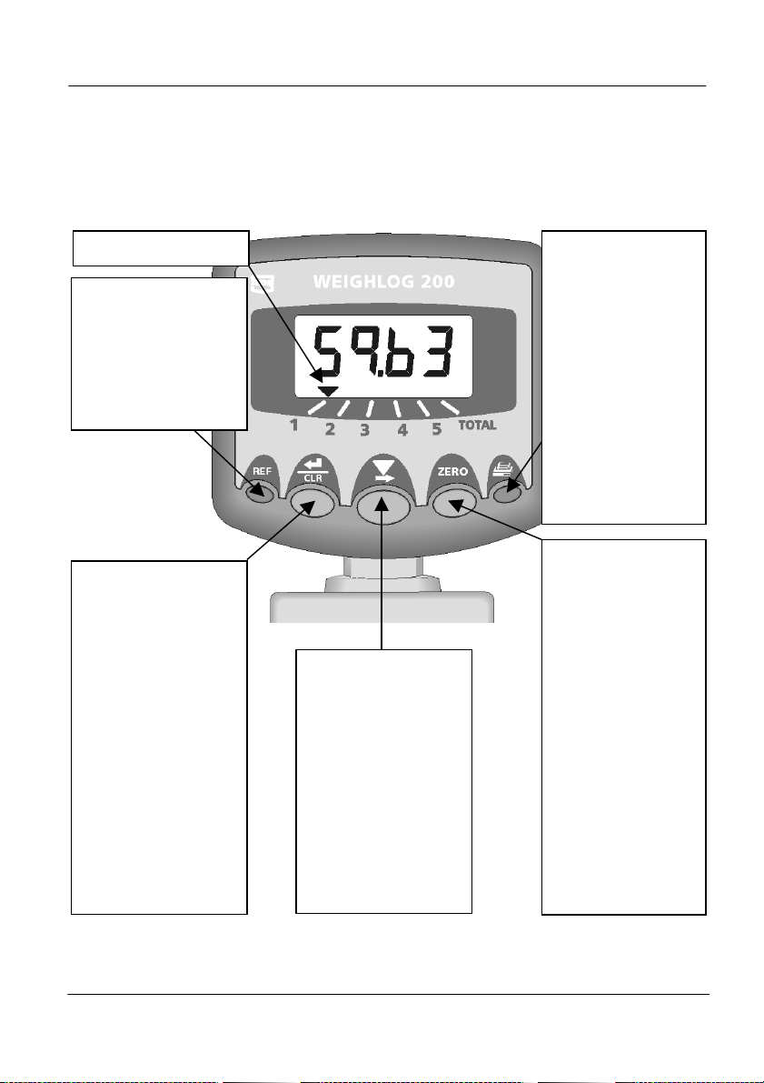
The instr ment has an ill minated 4-digit LCD display, 5 front panel switches,
an external Load Enter B tton, and an internal a dible alarm. An external
a dible alarm is optional. The instr ment is normally powered on via the
ignition circ it and recalls the f nction selected when last sed.
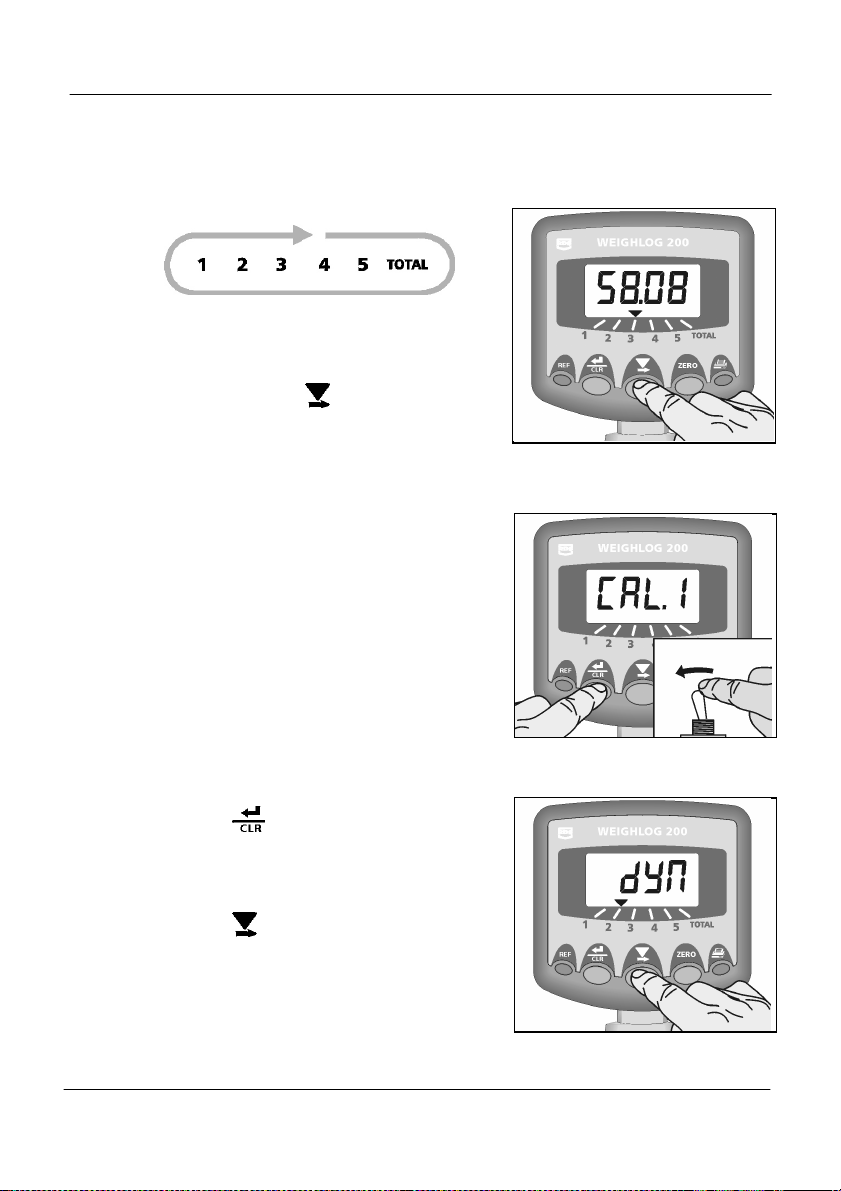
There are 5 individ al display channels available. These can be calibrated for
p to 5 different loader attachments, different trailers or different
commodities. Each channel will display the net b cket weight lifted at any
time. If req ired the b cket weight can be added to the total for the channel
in se and will also be added to the TOTAL channel, which acc m lates
weight from all of the five channels.
The instr ment has a Load Alarm f nction. If the load exceeds a preset
fig re, an a dible alarm is triggered and the weight display will flash.
The instr ment can be config red to a tomatically print each b cket weight
entered, or individ al load total when the instr ment is zeroed for the next
load. Also, yo can at any time print o t the acc m lated total for channel 1
to 5, and the Grand Total (channel 6).
For each channel yo can :
• Adj st the Weight Calibration Factor
• Set either Static or Dynamic Weighing Mode.
• Set the Zero Weight.
• Display and add the b cket weight to the s b-total.
• Receive a dible alarm confirmation of the zero and load entering.
• Print the last b cket weight a tomatically
• Print an acc m lated total
• Reset the acc m lated total (and a tomatically print a s mmary)
• Compensation for variable lift speed (dynamic weighing only)

OVERVIEW
5
Programming Modes
There are 3 programming modes with vario s calibration factors and defa lt
settings. Many of these settings are made on installation and do not normally
need to be changed nless the instr ment is moved on to a different loader.
The operator does not normally need to access the programming modes.
CAL Mode 1 is for weight calibration. The instr ment is calibrated
independently for each channel 1 to 5 (e.g. each channel can be dedicated
to s it a partic lar attachment or commodity). Channel 6 is sed to
programme the Overload Alarm.
CAL Mode 2 covers Speed Compensation Factors, Static weight reado t,
Man al weighing ( sing the REF b tton), Time, Date, and Units selection.
CAL Mode 3 is for Printer Setup.
NOTE: With careful operation, system accuracy can be as good as ±1% of lift
capacity although ± 2% is more common in practice.
Weighlog readings are not suitable as a legal basis for the sale of goods.

OVERVIEW
6
2 The Control Switches
There are five switches on the front panel sed individ ally or in combination
to programme, set, reset or select a f nction.
Channel Indicator
MANUAL WEIGHING
Press to man ally
sample a weight (i.e.
alternative t
o a ref/dir.
Sensor)
Defa lt setting = Off
EN ER /CLEAR
Pre
ss to add a b cket
weight to the channel
total.
HOLD to clear the
channel total. (If
config red, the
channel total is
a tomatically
printed).
Or
HOLD and power-on
to enter CAL Mode 1
ZERO BUCKE
WEIGH
Press and hold for 3
beeps.
(Press again to
cancel)
Weigh empty
b cket then press
the REMOTE
ENTER b tton to
zero
Or
HOLD and power-
on to enter CAL
Mode 2
PRIN ING
Channels 1-5
Press to print the
weight total for the
selected channel
Channel 6
Prints the weight
totals for channels
1-5 and the Grand
Total.
(Press ZERO to
cancel printing)
SELEC CHANNEL
Press and hold to
cycle thro gh
channels 1-5 (s b
totals) and channel
6
(Grand Total)
Or
HOLD and power-on
to enter CAL Mode 3

OVERVIEW
7
2.1 Display Units
The instr ment can be set to display nits as tons (USA)/ tonnes, kgs or lbs.
When set to the "kgs" or ‘lbs’ reado t option, the display will read p to
‘9990’ ro nded to the nearest 10 nits. Above this threshold (e.g. when
displaying any of the totals) the display will alternate between "lbs x 1000"
and any remainder. Therefore, the instr ment can display p to 999,990 lbs
The table below gives examples of the reado t.
Units – Channel otal Display
ons/tonnes kgs lbs
‘1.02’ ‘1020’ ‘2040’
kg x 1000 kgs lb x 1000 lbs
‘10.20’ ‘10‘ ‘-200’
(10,200 kg)
‘20 ‘ ‘-400’
(20,400 lbs)
‘102.0’ ‘102‘ ‘-000’
(102,000 kg)
‘204‘ ‘-000’
(204,000 lbs)
MAX. = ‘9999’
‘999‘ ‘-990’
(999,990 kg)
‘999‘ ‘-990’
(999,990 lbs)
2.2 Machine requirements
The Weighlog translates press re (or strain) to weight by means of a
calibration factor programmed into the instr ment. The acc racy of the
system depends to some extent on the following :
1. Operating emperature : Always allow the machine and the hydra lics to
warm p to the normal operating temperat re before commencing weighing.
2. Weighing on level ground : Avoid weighing when on a slope or a side
slope. Wherever possible weigh on a level area.
3. Vehicle movement : Best res lts are obtained when weighing while the
vehicle is stationary. It is important that the load does not bo nce or jerk as it
is lifted.

OVERVIEW
8
4. Maintenance : Keep yo r machine maintained in good condition. Things like
excessively worn b shings, pivot pins and slideways, as well as lack of
l brication to these areas can have an adverse effect on weighing acc racy.
NOTE: After any major servicing particularly if you have replaced worn components
or carried out welding repairs, you should re-calibrate the weighing system. If
the hydraulic system has been drained and re-filled you should also check for
any air which may have become trapped at the pressure sensor.
2.3 Lifting procedure
The correct lifting proced re is especially important for dynamic weighing.
The load sho ld be lifted smoothly and consistently thro gh the weighing
position. The best proced re is as follows :
1. Having picked p the load, crowd (roll) the b cket right back as far as it will
go.
2. P ll the lift lever right back with the engine at idle.
3. Increase engine revs to the "weighing speed" and lift smoothly witho t
bo ncing or jerking. Ens re that yo lift at the weighing speed as yo pass
thro gh the reference position (dynamic weighing).
If when lifting the bucket in dynamic weighing mode, the instrument
displays ‘FASt’ or ‘Slo’ and beeps 3 times, then lower and lift again at an
appropriate speed.
his also applies when checking the zero weight (section 3.3, 3.4).

PRELIMINARY SETTINGS
9
3. Before Weighing
3.1 Select Channel
Ens re that the correct channel is selected
for the attachment / commodity / trailer to
be weighed.
Simply press the b tton to cycle
thro gh the channels.
3.2 Select the Weighing Mode
In the normal operating mode, yo cannot
switch between Static and Dynamic
weighing mode on an individ al channel.
Separate channels are set p for either
Static weighing or Dynamic weighing, as
part of the weight calibration ro tine
(6.2.4). Yo then select the appropriate
channel for the weighing mode yo wish
to se.
Checking the Weighing Mode.
1. HOLD the b tton and power-on the
instr ment (Fig. 4). The display will show
“dYn” for dynamic weighing mode or
“StAt” for static weighing mode, for
channel 1.
2. Press the b tton to cycle thro gh the
other channels.
Figure 3 Select Channel
Figure Enter CAL Mode 1
Figure 5 Select Weighing Mode
ON

PRELIMINARY SETTINGS
10
3.3 Check Zero Weight
Yo sho ld check the zero weight
reg larly as part of the daily operating
ro tine. ALWAYS check zero weight if the
machine has been left idle for some time
and has cooled down.
The lifting proced re is different for
Dynamic and Static weighing modes. Note
the weighing mode set on the channel yo
have selected and follow the appropriate
proced re below.
1. Ens re that the b cket is completely
empty. Crowd (roll) the b cket right back
as far as it will go.
2.a Dynamic weighing mode : Lift the b cket
thro gh the reference position. Two beeps
will be heard. The display will show a
val e.
2.b Static weighing mode : Lift the b cket p
to the reference position and stop. A
single beep will be heard. If yo lift too
high, the display will show 4 dashes (fig.
6). If so, lower the b cket back down to
the reference position.
3. If the display reads within ±0.02t, or 20
kgs, or 40lbs (fig. 7 depending on the
display nits selected, this is within the
repeatability of the Weighlog system and
can be accepted witho t zeroing the
weight. Simply contin e loading as
normal.
4. If the display reads more than ±0.02t, or
20 kgs, or 40lbs (fig. 8), then yo sho ld
zero the weight (see 3.4).
Figure 6
Static Mode
–
too high
Figure 8
Not OK
Figure 7
OK

PRELIMINARY SETTINGS
11
3.4 Zero Weight (Set Tare)
The weight sho ld be zeroed if the weight
reading for an empty b cket is more than
±0.02t, or 20 kgs, or 40lbs.
Ens re that the hydra lic system is p to
it's normal operating temperat re. It may
be necessary to lift and lower a f ll b cket
for a few min tes to exercise the
hydra lics and warm the system p.
Observe the correct lifting ro tine (section
2.2).
1. Ens re that the b cket is completely
empty. Crowd (roll) the b cket right back
as far as it will go.
2. SELECT THE CHANNEL TO BE ZEROED.
3. Press and hold the ZERO b tton (fig 9).
The a dible alarm will beep THREE times
and the display will flash “0.00”.
4.a Dynamic weighing mode : Lift the b cket
thro gh the reference position. Two beeps
will be heard. The display will show a
val e.
4.b Static weighing mode : Lift the b cket p
to the reference position and stop. A
single beep will be heard. If yo lift too
high, the display will show 4 dashes (fig.
6). If so, lower the b cket back down to
the reference position.
5. As the weight is registered, the display will
contin e to flash b t may change to show
a n mber (fig. 10). Press the REMOTE
ENTER BUTTON to zero the weight (fig.
11). The alarm will so nd one beep to
confirm the weight is zeroed.
NOTE: Press ZERO button to cancel routine.
6. Repeat the ro tine several times to
confirm the system is correctly zeroed.
F
igure 9
Figure 11
Figure 10

WEIGHING
12
4 Weighing
There are two f ndamentally different ways of weighing with the Weighlog -
Dynamic weighing and Static weighing. Yo can select the weighing method
for each of the five channels on the instr ment.
4.1 Dynamic Weighing
Dynamic weighing means that the weight is meas red witho t interr pting
the lift. The load is lifted straight thro gh the reference position. Dynamic
weighing can give consistent res lts witho t significantly slowing down the
loading cycle, b t it does rely on a certain degree of care on the part of the
operator (section 2.2).
1. Lift the load through the reference position. The alarm will so nd two beeps.
The display will then show the net weight in the b cket. The weight will
remain displayed ntil yo lower the b cket below the reference position.
2. Press either the b tton or the Remote Enter B tton to add the weight to
the s b-total for the selected channel (and to the TOTAL channel).
NOTE: If “Slo” or “FASt” is displayed instead of a calculated weight, you have lifted
too slowly or too quickly for speed compensation to work. Try again (or
recalibrate over a more suitable lift speed range – 6.2. ).
4.2 Static weighing
Static weighing req ires the load to be lifted or lowered to the reference
position and held there. The display will show a "live reading" (see note)
which will fl ct ate as the machine settles. Yo can tip off excess material as
req ired, therefore static weighing is ideal for the last b cket load if yo are
aiming to reach a target load.
NOTE: The “live” readout is enabled via the “Live Static” setting in CAL Mode 2.
1. Lift the load p to the weighing position. The alarm will so nd one beep and
the "live" weight will be displayed. If yo go too high the display will show 4
bars (fig. 6).
2. It is a pec liarity of hydra lic systems that the press re (and therefore the
load reading) will diminish for some time after the load is stopped at the
reference position, therefore yo sho ld allow a short delay for the weight
reading to settle down.
3. Press either the b tton or the Remote Enter B tton to add the weight to
the s b-total for the selected channel (and to the TOTAL channel).

WEIGHING
13
4.3 Trailer Weighing
Specifically for weighing applications other than for front-end loaders, e.g. for
trailer weighing, a special feat re of the Weighlog 200 allows yo to man ally
trigger a weighing sample sing the REF b tton. In effect, the REF b tton
performs the f nction of a Reference/Direction sensor.
The REF b tton is normally disabled. It is enabled via CAL Mode 2. It can
also be enabled in addition to a Ref/Dir sensor ('AUTO' setting), in which case
a weight reading is triggered by either the sensor or the REF b tton,
whichever is triggered first.
Procedure:
1. Lift the tipper body slightly so that the lift
ram becomes press rised.
NO E: Always sample the trailer weight with
the tipper body raised to the same
position at which weight calibration was
performed.
Sampling at a different position will
adversely affect weighing accuracy.
2. Press the REF b tton (Fig. 12a).
With Static weighing, when the REF B tton
is pressed, a live static reading is
displayed. To cancel the weight reading
and ret rn to the s b-total display, press
the REF b tton again.
3. While the weight is displayed, press either
the b tton or the Remote Enter
b tton to add the weight to the s b-total
for the selected channel (and to the
TOTAL channel).
If the selected channel is set p, the
weight will appear on the display for 5
seconds before it cancels to zero.
NOTE: If the “ENT” print mode is enabled, an automatic printout (in the “REC” format)
is made after the REF button is pressed.
Figure
12a
Trailer Weighing

WEIGHING
14
4.4 Incorrect Weight readings
After performing the initial weight calibration and loading a few tr cks, yo
may find that the load readings from the instr ment are consistently different
from weighbridge (weighscale) readings. This sit ation can also occ r after
maintenance or repair to the loading shovel e.g. changing a b cket.
If the Weighlog reading is more than the tr e weight, the factor is decreased
and vice versa, if the Weighlog reading is less than the tr e weight, the factor
is increased.
Therefore, if yo find a consistent discrepancy between the Weighlog
readings and the weighbridge readings, int itively, yo can then n dge the
cal factor p or down as req ired
E.g. If the Weighlog reading is 10% high, then red ce the cal. factor by 10%.
The act al calibration factor can also be determined by a simple calc lation
sing the tr e weight and the displayed weight as follows :
Correct factor = existing factor x tr e weight
Weighlog reading
The calibration factor can be adj sted either in Cal Mode 1 or from the
normal operating mode.
Adjusting a Weight reading in normal operating mode
With the instr ment in the normal
operating mode, lift a known weight. If
the displayed weight differs, then yo can
easily correct it (‘n dge’) as follows.
Press and hold the REF b tton for 5
seconds ntil the display is as shown.
Contin e holding the REF b tton and
either adj st the weight p sing the
ZERO key, or down sing the PRINT
(o ter right) key.
Release the REF key. The display shows
‘DonE’ and a new calibration factor is
stored in memory.
Figure 12b: Adjust Cal Factor

WEIGHING
15
4.5 Load Alarm
Default: - Alarm Off
The instr ment has a Load Alarm f nction. If the load exceeds a preset fig re
set in CAL Mode 2 (6.2.6), an a dible alarm is triggered and the weight
display will flash.
The alarm will contin e and weighing is not possible ntil the overload
condition ceases. The load alarm is operative at any lift position.
4.6 Printing
Printing a Channel total (Channels 1 to 5)
Select the appropriate channel then
press the button to print the total
weight that has been recorded to that
channel since it was last reset.
If the printer mode is set to “REC”, a short
“Job Record” will be printed. (Fig. 13).
If the printer total is set to “ROLL”, a “Job
Record” will be printed with space for the
c stomer name, address and signat re
(Fig. 14).
NOTE: Pressing the ZERO button will cancel
routine.
Printing a Grand Total
Select channel 6 and press the b tton
to print a “Totals S mmary” of the
individ al totals for channels 1 to 5, and
the Grand Total recorded to channel 6
(Fig.15a).
NOTE: Pressing the ZERO button will cancel
routine.
Figure 13 : A Job Record (“REC”)
Figure 1 : A Job Record (“ROLL”)

WEIGHING
16
Automatic Printing
NOTE: The print mode in CAL Mode 3 (6. .2) must
be set to either “REC” “ROLL” or “ENT” to
enable automatic printing.
“REC” / “ROLL” Print Mode
The instr ment will a tomatically generate
a “REC” or “ROLL” type printo t when yo
reset any channel to zero, for example,.
after completing a load.
The job n mber increments by one each
time any channel total is reset.
“EN ” Print Mode
If “ENT” print mode is set in CAL Mode 3,
the instr ment will a tomatically print the
weight of the last b cket lift/trailer load
(Fig. 15b), when yo press the b tton
or the Remote Enter switch to add the
b cket weight/trailer load to the channel
total.
NOTE: Pressing the ZERO button will cancel routine.
Figure 15a : Totals Summary
Figure 15b : “ENT” Printout

WEIGHING
17
5 Totals
5.1 Reset Individual Sub-totals / Grand Total
Channels 1 to 6 can be reset
independently.
1. Select the appropriate channel.
2. Press and hold the b tton or the
Remote Enter b tton for 5 seconds.
The display will flash 5 times and then go
to zero.
If “REC” or “ROLL” print mode is enabled,
the instr ment will a tomatically generate
a printo t.
5.2 Display Time
1. Select the TOTAL channel.
2. Press and hold the ZERO b tton (Fig. 17).
The time displays in 24hr format (hh:mm)
Figure 16: Reset Grand Total
Figure 17: Display Time

WEIGHING
18
6 Calibration
6.1 Programme a Numeric Setting
This applies to any n meric setting that
needs changing. With the factor
displayed, normally, the left-hand digit of
the fo r-digit n mber will be flashing
(Fig.18).
1. While holding the b tton, PRESS and
RELEASE the b tton to SELECT the
digit yo want to change, or decimal point
to move.
1.000, 1.000, 1.000, 1.000, 1.000
2. Keep holding the b tton, HOLD the
b tton to cycle the digit from 0 to 9, or to
move the decimal point.
1.000, 1.100, 1.200, 1.300, 1.400
3. Release the b tton and the next digit
will flash.
4. Repeat steps 1, 2 and 3 as necessary to
change the other digits, or if yo make a
mistake.
Entering a Negative Value
A negative val e is indicated by the
MIDDLE c rsor on the left of the display
(Fig.20).
To switch between positive and negative,
perform step 1 above, to select the
flashing c rsors (Fig.19).
As in step 2 above, HOLD the b tton
ntil the middle c rsor appears and then
release the b tton. The val e then
becomes negative.
Figure 18
Figure 19
Figure 20

CALIBRATION
19
6.2 CAL Mode 1 – Weight Calibration
The calibration factor is an arbitrary n mber relating the hydra lic press re (or
strain meas rement) in the lift system to the load in the b cket. Acc rate
res lts from the Weighlog can only be achieved if the calibration proced re
has been carried o t caref lly and in the correct seq ence. Decide which
attachment/commodity applies to which channel and whether static weighing
or dynamic weighing is appropriate. Make a note of this on the chart provided
at the back of this man al.
Perform the following calibration steps for each channel to be calibrated.
Refer to the appropriate sections for additional information.
NO E 2:
A full bucket must be used so that the software can calculate the
difference between an empty bucket and a fu
ll bucket. Using a few
hundred kilos only as a test load will result in a poor Autocal.
NO E 1:
Fast lifts are normally the fastest lift speed of the machine. If not, both
the fast zero and fast load lifts should be carried out at exactly the same
speeds for a successful Autocal.
NO E 3:
When c
alibrating for dynamic weighing, ensure that the magnet has
moved well above the reference and direction sensors, otherwise the
speed compensation calibration routine may not be correctly
implemented.

CALIBRATION
20
3.4
Set Zero
(with empty b cket)
6.2.2
Set Weighing Mode
(“
dYn
” or “
StAt
”)
6.2.3
Set Initial Cal Factor
(= Max. Load Capacity in tonnes)
6.2.4 (i)
6.2.4 (ii)
Weight Cal. Routine
DYN. MODE STAT. MODE
“Load FASt” Fast lift (f ll load)
“Load Slo” Slow lift (f ll load)
“Empt FASt” Fast lift (empty b cket) (note 1-p.18)
“Empt Slo” Slow lift (empty b cket)
“ZERO LIF ” – Sets Prop. Scaling/Speed “ZERO LIF ”
Comp. for all dynamic channels Lift empty b cket
Determine Cal Factor (the “LOAD” seq ence)
Enter known weight on instr ment
“LOAd LIFt”
Place a known weight in the b cket and lift at normal speed
“DONE”
Table of contents
Other RDS Technology Accessories manuals
Popular Accessories manuals by other brands

Leuze electronic
Leuze electronic LES 36 manual

Yamato
Yamato IN604 instruction manual

Panasonic
Panasonic MA2J704 Specification sheet

Antelope
Antelope Orion owner's manual

LEGRAND
LEGRAND Wattstopper UW-100 installation instructions

Lithonia Lighting
Lithonia Lighting OFLR 9LN 120 MO BZ M2 operating instructions