PP5099/2023/Issue 1
Page 4 of 27
Suitability
Building Considerations
The following should be considered when considering REACH Wireless for a building. Each of the below items will neg-
atively impact signal strength or consistency. This does not necessarily prevent REACH from being a viable solution, but
should be considered during the up-front site survey to help plan the system layout:
• Thick, solid walls e.g. historic buildings
• Large amounts of metal in the structure such as steel girders, metal wire mesh, HVAC systems etc.
• Cabling – especially heavy gauge or high current
Wireless Considerations
Be aware of other wireless equipment in the installation area that operates within the same 868Mhz band. If possible,
avoid using the same 868Mhz channels as these devices to avoid communication issues.
If installing near an Apollo XPander system, please also be aware that RF channel frequencies are not aligned across
these systems, so selecting dierent channel numbers may still result in clashes. Please refer to the RF channel loop-up
sheet (appendix 1) to compare.
A 2m minimum distance must be kept between all REACH Wireless products to prevent signal loss.
Wiring Considerations
Apply mandatory codes of practice and standards of your country.
• Don’t install wireless devices in the vicinity of large electrical equipment, fluorescent light fixtures, computers or their
power and network cabling.
• Don’t install wireless devices in the vicinity of large metal objects, structures or metal ceiling structures.
• Do ensure that all REACH products adhere to a minimum installation distance of 2 meters between each other.
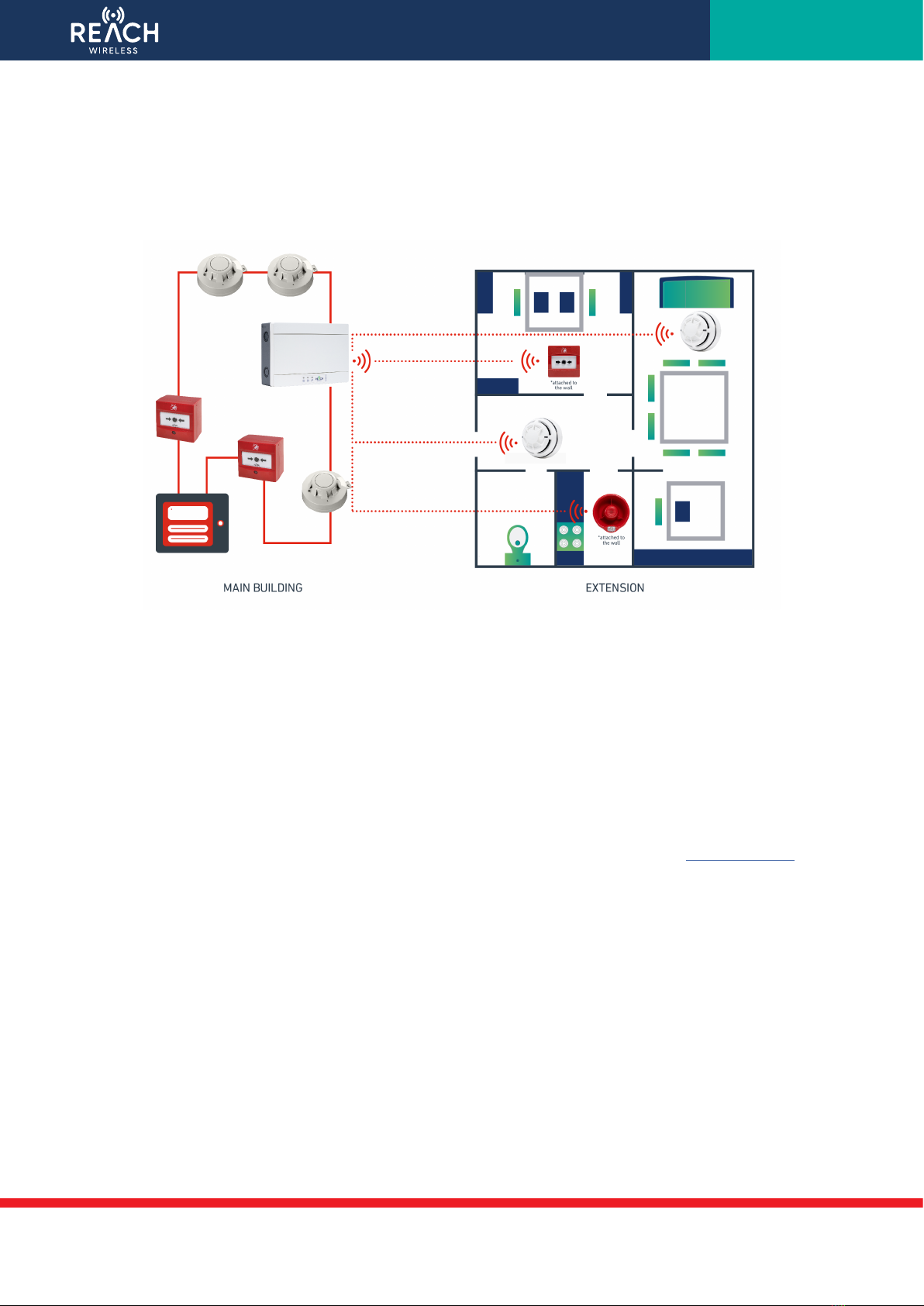
• Do install the RW1700-030APO Loop Interface at a height of at least 2 - 2.5 meters from the floor, fixed flat on the wall.
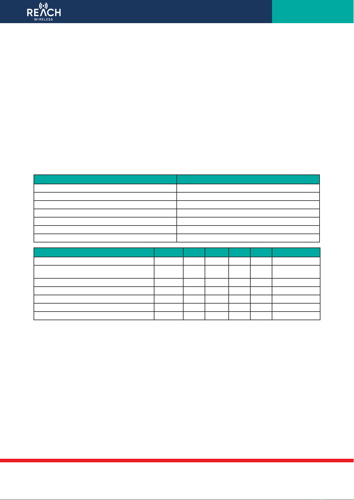
Apollo Protocol Support & Panel Compatibility
REACH Wireless is a hybrid wireless solution, meaning it must be connected to a wired loop to function and cannot operate
as a standalone solution.
The RW1700-030APO loop interface acts as the wireless panel for the Reach Wireless products. It is the primary device in
the system and acts as the parent or host of the wireless network. The RW1700-030APO loop-interface must be connect-
ed to the wired addressable loop in order to communicate with the wired loop’s control panel and in order to power on. It
will act as the bridge between the wired and wireless network, translating communications between the wired panel and
wireless devices and vice versa.
REACH communicates using the Apollo XP95 protocol natively, meaning it is compatible with Discovery and CoreProtocol
loops as a legacy device. Its XP95 communication is designed to mimic Apollo’s legacy wireless solution, XPander, for
maximum compatibility with panels. Fire panel features and technical specifications vary, so please refer to the panel’s
compatibility list to check for REACH Wireless support.