Real Carriage Door & Sliding Hardware Franklin Autoswing User manual

Franklin Autoswing
Installation Manual

It is recommended that you have a low voltage electrician,
or trade member familiar with gate installations to install the
operator. You may call us or the manufacturer to see if there
is anyone in your area familiar with the Franklin Autoswing.
Real Carriage Door & Sliding Hardware is not liable for any
damage that occurs during install, and replacements are the
sole responsibility of the installer and customer. The manu-
facturer does carry a warranty for any defects or issues that
are from manufacturing only and will have to be tested by
the manufacturer’s technical team before sending replace-
ments.
It is also a good idea to install a surge protector to avoid any
damage to the operator. The operator can be damaged by
power surges or faulty wiring.
CAUTION
Thank you for buying this product, our company is
sure that you will be more than satised with the
product’s performance. The product is supplied with
a “Warnings” leaet and an “Instruction booklet”.
These should both be read carefully as they provide
important information about safety, installation,
operation and maintenance. This product complies
with the recognized
technical standards and safety regulations.
1) GENERAL OUTLINE
The control panel is supplied by the manufacturer
with standard settings. Any alteration must be set
by means of the incorporated display programmer
or by means of UNIPRO. The Control unit
completely supports the EELINK protocol. Its main
characteristics are:
- Control of two low-voltage motors up to 40W
power
- Electronic torque setting with obstacle detection
- Limit-switch control inputs
- Separate inputs for safety devices
- Incorporated rolling-code radio receiver with
transmitter cloning
- Soft start and close
The IGEA-BT (24V) is suitable for residential use and
has been designed for swing gates with particularly
large gate posts. The drive arm, built with a special
anti-shearing shape, allows the leaves to be moved
when the controller is considerably out of place
with respect to the fulcrum of the leaves. The non-
reversible electro-mechanical motor maintains the
stop during closing and opening. The release knob
with personalized key, tted outside each operator,
makes manual operation extremely easy.
2) SAFETY
If correctly installed and used, this automation
device satises the required safety level standards.
However, it is advisable to observe some practical
rules in order to avoid accidental problems. Before
using the automation device, carefully read the
operation instructions and keep them for future
reference.
• Keep children, persons and things outside the
automation working area, particularly during
operation. An incorrect installation or improper
use of the product can cause damage to persons,
animals or things.
• Keep radio control or other control devices out of
children’s reach, in order to
avoid any unintentional automation activation.
• Do not intentionally oppose the leaf movement.
• BFT and Real Carriage Door & Sliding Hardware
declines all responsibility for any consequences
resulting from failure to observe Good Technical
Practice when constructing closing structures (door,
gates etc.), as well as from any deformation which
might occur during use.
• The installation must comply with the provisions
set out by the following directives: 89/336/
CEE, 73/23/EEC, 98/37/EEC and subsequent
amendments.
• Do not attempt to open the gate by hand, if the
actuator has not been released by means of the
appropriate release knob.
• Do not modify the automation components.
• In case of malfunction, disconnect the power
supply, activate the emergency release to gain
access to the actuator and request the assistance
of a qualied technician (installer).
• Before proceeding to any external cleaning
operation, disconnect the main powers supply and
at least one of the battery pole, if tted.
• Check that grounding is carried out correctly:
connect all metal parts for closure (doors, gates
etc.) and all system components provided with an
earth terminal.
• Fit all the safety devices (photocells, electric edges
etc.) which are needed to protect the area from
any danger caused by squashing, conveying and
shearing, according to and in compliance with the
applicable directives and technical standards.
All California residents must have a battery backup installed with
electronic door openers according to Senate Bill No. 969. Please call our
main line for assistance or check out our website for additional
information.

• Keep the photocell optical components and
luminous signal indication devices clean. Check
that the photocells are not obscured by branches or
shrubs.
• For any direct assistance to the automation
system, request the assistance of a qualied
technician (installer).
• Have qualied personnel check the automation
system once a year.
• Entrance is reserved for vehicles, provide a
separate entrance for pedestrians.
3) SCRAPPING
Warning: This operation should only be carried out
by qualied personnel. Materials must be disposed
of in conformity with the current regulations. In case
of scrapping, the automation devices do not entail
any particular risks or danger. In case of materials
to be recycled, these should be sorted out by type
(electrical components, copper, aluminum, plastic
etc.).
4) DISMANTLING
Warning: This operation should only be carried out
by qualied personnel. When the control unit is
disassembled to be reassembled on another site,
proceed as follows:
• Disconnect the power supply and the entire
electrical installation.
• In the case where some of the components cannot
be removed or are damaged, they must be replaced.
5) FUNCTIONS
FOR THE INSTALLER: Fill in the table with the
parameters set, in order to facilitate future
modications and maintenance operations.
The preset values are indicated between square
brackets [ ].
WARNINGS
Correct controller operation is only ensured
when the data contained in the present manual
are observed. The company is not to be held
responsible for any damage resulting from failure
to observe the installation standards and the
instructions contained in the present manual.
The descriptions and illustrations contained in the
present manual are not binding. The Company
reserves the right to make any alterations deemed
appropriate for the technical, manufacturing and
commercial improvement of the product, while
leaving the essential product features unchanged,
at any time and without undertaking to update the
present publication.
ATTENTION! The IGEA-BT model controller is not
equipped with mechanical torque adjustment. It
is compulsory to use a control panel of the same
manufacturer, in compliance with the basic safety
requirements of directives 73/23/CEE, 89/336/
CEE, 89/37/CEE equipped with appropriate electric
adjustment of the torque.
Correct controller operation is only ensured
when the data contained in the present manual
are observed. The company is not to be held
responsible for any damage resulting from failure
to observe the installation standards and the
instructions contained in the present manual.
The descriptions and illustrations contained in the
present manual are not binding. The Company
reserves the right to make any alterations deemed
appropriate for the technical, manufacturing and
commercial improvement of the product, while
leaving the essential product features unchanged,
at any time and without undertaking to update the
present publication.
Table of Contents
System Overview....................................................................6
Specications ........................................................................7
Igea Motor Installation............................................................8
Mounting the Control Unit.......................................................11
Wiring Simplied ....................................................................12
Autoset Programming for Quick Setup....................................14
Programming Features...........................................................16
Installing Wired Wall Button....................................................21
Additional Remotes ................................................................23
Optional Accessories .............................................................24
Homelink Programming..........................................................25
Wireless Wall Button...............................................................26
Outdoor Wireless Keypad .......................................................27
Wi-Fi Hub ..............................................................................29
Full Programming Menu ........................................................31
Additional Safety Devices.......................................................35
Battery Backup.......................................................................36
Arched Door Applications.......................................................37
Error01 Troubleshooting Guide ...............................................39

Page 7SpecicationsPage 6 System Overview Page 7Specications
SpecicationsSystem Overview
The below drawing is an example of typical
component placement and wiring.
• Please note that the Control Housing must have
holes drilled into it to run the wires
• UL Listed stress-relief connectors are
recommended. The Control Unit should be
removed from the wall for drilling the holes,
and be careful to not damage the box or its
contents
• Refer to “Wiring Simplied” for more detailed
views of Control Unit connections.
• Surge protection and a dedicated circuit are
encouraged
A. Control Unit Housing
B. Left Motor
C. Right Motor
D. Receiver Photoeye
E. Transmitter Photoeye
F. Wired Wall Button
G. 4 Button Remote (2)
H. Extended Range Antenna (optional)
TypicalSystemOverview
Belowisanexampleoftypicalcomponentplacementandwiring.PleasenotethattheControlHousing
musthaveholesdrilledintoittorunthewires.ULListedstress‐reliefconnectorsarerecommended.Be
careful not to damage the panel when drilling into the housing! It is a good idea to remove the panel
while drilling. Referto“MasterWiringDiagram”formoredetailedviewsofControlPanelconnec�ons.
Surgeprotec�onandadedicatedcircuitareencouraged.
*Motors are low voltage. Use braided wire.
Increase wire gauge if motors mounted
more than 20’ from control housing.
**From lowest part of jamb to ceiling line.
A. Control Housing (dims 7.25” x 8.75” x 3.5”)
B. Left Motor
C. Right Motor
D. Receiver Photoeye
E. Transmitter Photoeye
F. Wall Pushbutton
G. 2-Button Remote Transmitter (2)
H. Antenna (for extra range applications)
TM
Franklin Autoswing Installation Manual
© 2012 Copyright Real Carriage Door Company, Inc
7
6
6
5
Franklin Autoswing Specs
Mounng Clear-
ance
7-1/2” above jamb
Voltage 24 V
Power Supply 120 V 60Hz Sin-
gle-phase
Absorbed Power .05hp (40 W)
Opening or Closing
Time
15 sec
Impact Reacon Torque Limiter on
Control Unit
Manual Release Release knob with
key
Operang Cycle Intensive use
Environmental
Condions
5 degrees F – 140
degrees F
Degree of Protec-
on
IP44
Operator Weight 35 lbs
Door Width Max Up to 10
Door Max Surface
Area
120 2
Max Open Angle Up to 125 degrees
Weight Limit 550 lbs

Page 9SpecicationsPage 8 Igea Motor Installation Page 9Igea Motor Installation
12. Repeat these steps for the other leaf, if installed
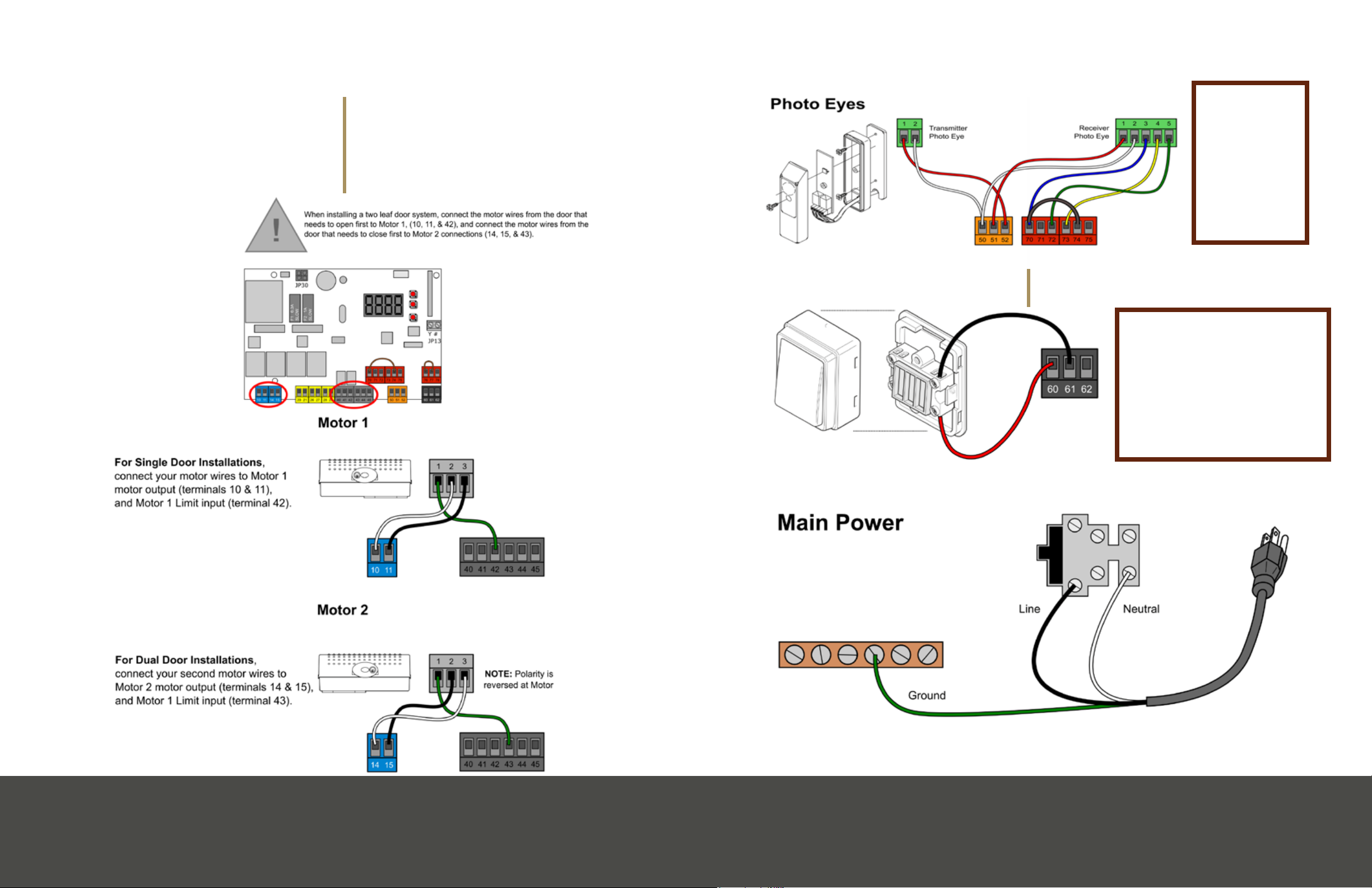
Wiring the Motor
1. Locate the stress relieving cord-grip
2. Attach connecting nut (F) to grip body (G).
Tighten securely using nger pressure only
3. Slip compression nut (H) over a length of 16/3
(16 Gauge, 3 strand) motor wire and thread wire
through the assembled cord-grip
4. Tighten the compression nut (H) with nger
pressure only
5. Refer to Wiring Simplied for wiring from motor
to control board terminals
Installing the Limit Switches
1. Install the full cam on top of the metal shaft
• Then install the ring cam on top of the full cam
• Do not fully tighten the xing screws.
2. When the door
is fully open,
rotate the
corresponding
cam (g.
4), until you
hear a ‘click’
indicating the limit switch has been depressed
• Lock it in position by tightening the appropriate
screws
• Repeat for the fully closed position
• Refer to “Manual Operation Mode” to manually
swing the door.
3. Swing the door slowly to its open and close
positions, listening to see that the ‘click’ of the
limits switch occurs where desired
Note: that the left motor’s cams (close vs open) are
inverted from those of the right motor. Adjust as
necessary
Left Motor (as viewed from inside)
Stop Position Cam Position
Close Top
Open Bottom
Right Motor (as viewed from inside)
Stop Position Cam Position
Close Bottom
Open Top
Installa�onofLimitSwitches
1.Installthelimitswitchreferncecamsas
showning.3.Installthefullcamontopof
themetalsha,theninstalltheringcamon
topofthefullcam.Donotfullyghtenthe
xingscrews.
2.Whenthedoorisfullyopen,rotatethe
correspondingcam(g.4),unlyouheara
‘click’indicangthelimitswitchhasbeen
depressed,thenlockitinposionby
ghteningtheappropriatescrews.Repeatfor
thefullyclosedposion.Referto“Manual
OperaonMode”tomanuallyswingthedoor.
3.Swingthedoorslowlytoitsopenandclose
posions,listeningtoseethatthe‘click’of
thelimitsswitchoccurswheredesired.Adjust
asnecessary.
Fig4.LimitSwitchfuncons
LEFTMOTOR
(viewedfrominside)
RIGHTMOTOR
(viewedfrominside)
CLOSELIMITCAM
OPENLIMITCAM
CLOSELIMIT
SWITCH
OPENLIMIT
SWITCH
OPENLIMITCAM
CLOSELIMIT
CAM
OPENLIMIT
SWITCH
CLOSELIMIT
SWITCH
Fig3.LimitSwitchinstallaon
FULLCAMRINGCAM
Franklin Autoswing Installation Manual
TM
10
© 2012 Copyright Real Carriage Door Company, Inc
Igea Motor Installation
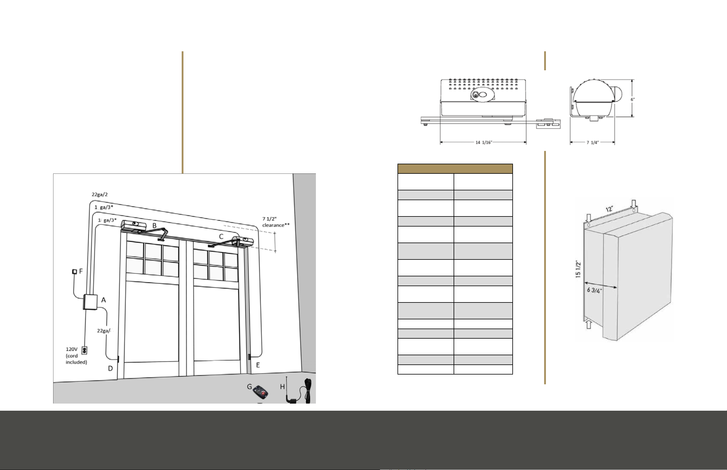
TIP: Before mounting, refer to “Typical System
Overview” for prewiring.
• For a very ‘clean’ installation, mount the unit
directly on the head casing (if at prole)
• This motor positioning is for outswing doors
only
1. Remove the cover from the motor and set aside
2. Remove the motor from the base plate by
loosening the 4 bolts on the bottom of the motor
3. Position the base plate (note that body of the
motor should extend toward the side jamb) about 7”
from the edge of the door*
• Level the plate and mark the locations of the
holes.
• TIP: For most applications, centering the
bottom row of holes on the jamb makes for the
most secure installation.
NOTE: See page 37 for arched door applications.
4. Level and mount the plate with minimum 3/8” x
4” lag bolts (not supplied)
• For proper arm clearance, the bottom of the
plate must no higher than the lowest part of the
jamb
• Always make certain that the lag bolts penetrate
solid header and/ or
blocking material
5. Re-attach the motor to
the base plate and tighten
securely. Be sure that the
motor is seated properly in
its plastic housing
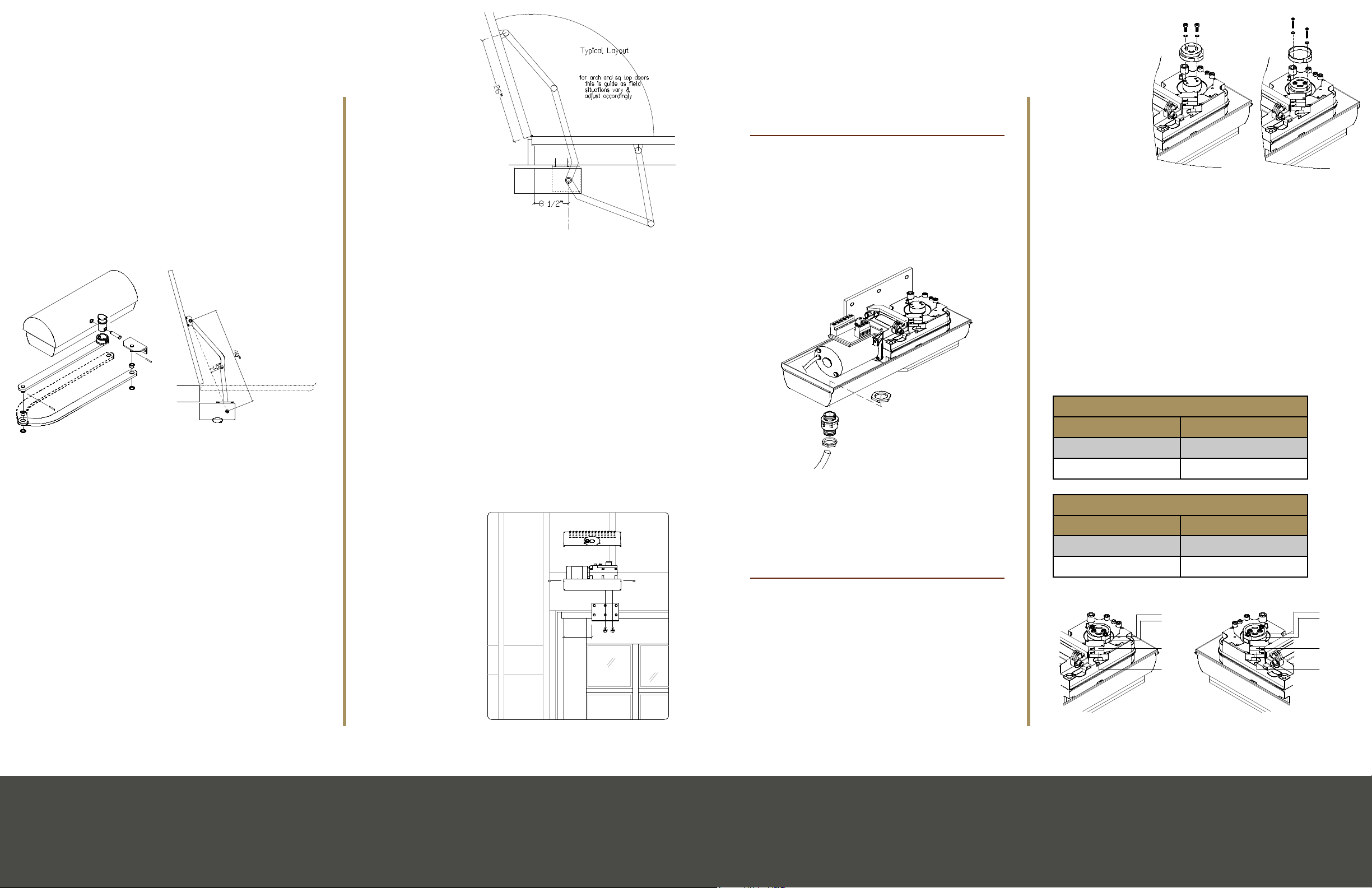
6. Assemble the articulated
lever arm and door coupling as
shown in g. 1.
• Connect straight arm and door coupling to
curved arm using plastic sleeve (K) and washer
(L)
• Secure together with rolled pin (M). The
dashed arm indicates the setup for the right
motor (viewed from inside)
7. Slide the assembled arm onto the transmission
shaft at the base of the motor
• Fasten it using the long pin (N) and C-ring (O)
8. Manually release the operator (See “Manual
Operation Mode”)
9. Open the door to the desired ‘fully open’ point
(approximately 105 degrees is recommended)
• With a measuring tape, mark the centerline
of the door mounting bracket at 40” from the
center of the
shaft (g. 2)
• Making sure that
the arm is level,
Mount the arm
to the door with
#14 x 1-1/2” pan
head screws
(not supplied)
10. Check clearance
and movement by
swinging door slowly
11. Relock the motor
(take out of manual
release mode)
1.Removethecovertothemotorandsetaside.
2.Removethemotorfromthebaseplatebylooseningthe4boltsontheboomofthemotor.
3.Posionthebaseplate(notethatbodyofthemotorshouldextendtowardthesidejamb)about7”fromtheedge
ofthedoor*.Leveltheplateandmarkthelocaonsoftheholes.TIP:Formostapplicaons,centeringtheboom
rowofholesonthejambmakesforthemostsecureinstallaon.
Lebaseplateposion,squaretop
door(interiorview)
Installa�onofMotor
TIP:Beforemounng,referto“TypicalSystemOverview”forprewiring.Foravery‘clean’
installaon,mounttheunitdirectlyontheheadcasing(ifatprole).Notethatthismotor
posioningisforoutswing doors only.
4.Levelandmounttheplatewithminimum3/8”x4”lagbolts(notsupplied).Forproperarmclearance,theboom
oftheplatemustnohigherthanthelowestpartofthejamb.Alwaysmakecertainthatthelagboltspenetratesolid
headerand/orblockingmaterial.
5.Reaachthemotortothebaseplateandghtensecurely.Besurethatthemotorisseatedproperlyinitsplasc
housing.
*NOTE: There are limita�ons for certain arch‐top radii rela�ve to the door width. See table in
APPENDIX C for allowable radii, and APPENDIX D for more help in posi�oning.
Lebaseplateposion,archtop
door(interiorview)
7”
7”
Franklin Autoswing Installation Manual
TM
8
© 2012 Copyright Real Carriage Door Company, Inc
6.Assemblethearculatedleverarmanddoorcouplingasshowning.1.Connectstraightarmanddoorcouplingto
curvedarmusingplascsleeve(K)andwasher(L).Securetogetherwithrolledpin(M).Thedashedarmindicates
thesetupfortherightmotor(viewedfrominside).
7.Slidetheassembledarmontothetransmissionshaatthebaseofthemotor,andfastenitusingthelongpin(N)
andCring(O).
8.Manuallyreleasetheoperator(See“ManualOperaonMode”).
9.Openthedoortothedesired‘fullyopen’point(approx105degreesisrecommended).Withameasuringtape,
markthecenterlineofthedoormounngbracketat40”fromthecenterofthesha(g.2).Makingsurethatthe
armislevel,Mountthearmtothedoorwith#14x11/2”panheadscrews(notsupplied)
10.Checkclearanceandmovementbyswingingdoorslowly.
11.Relockthemotor(takeoutofmanualreleasemode).
12.Repeatthesestepsfortheotherleaf,ifinstalled.
Installa�onofMotor(Con�nued)
Fig1.ArmAssemblyFig2.Armposioning
K
L
M
N
O
NOTE:
1.5” is minimum allowable arm
bend. Distances over 1.5” are
acceptable.
TM
Franklin Autoswing Installation Manual
© 2012 Copyright Real Carriage Door Company, Inc
9
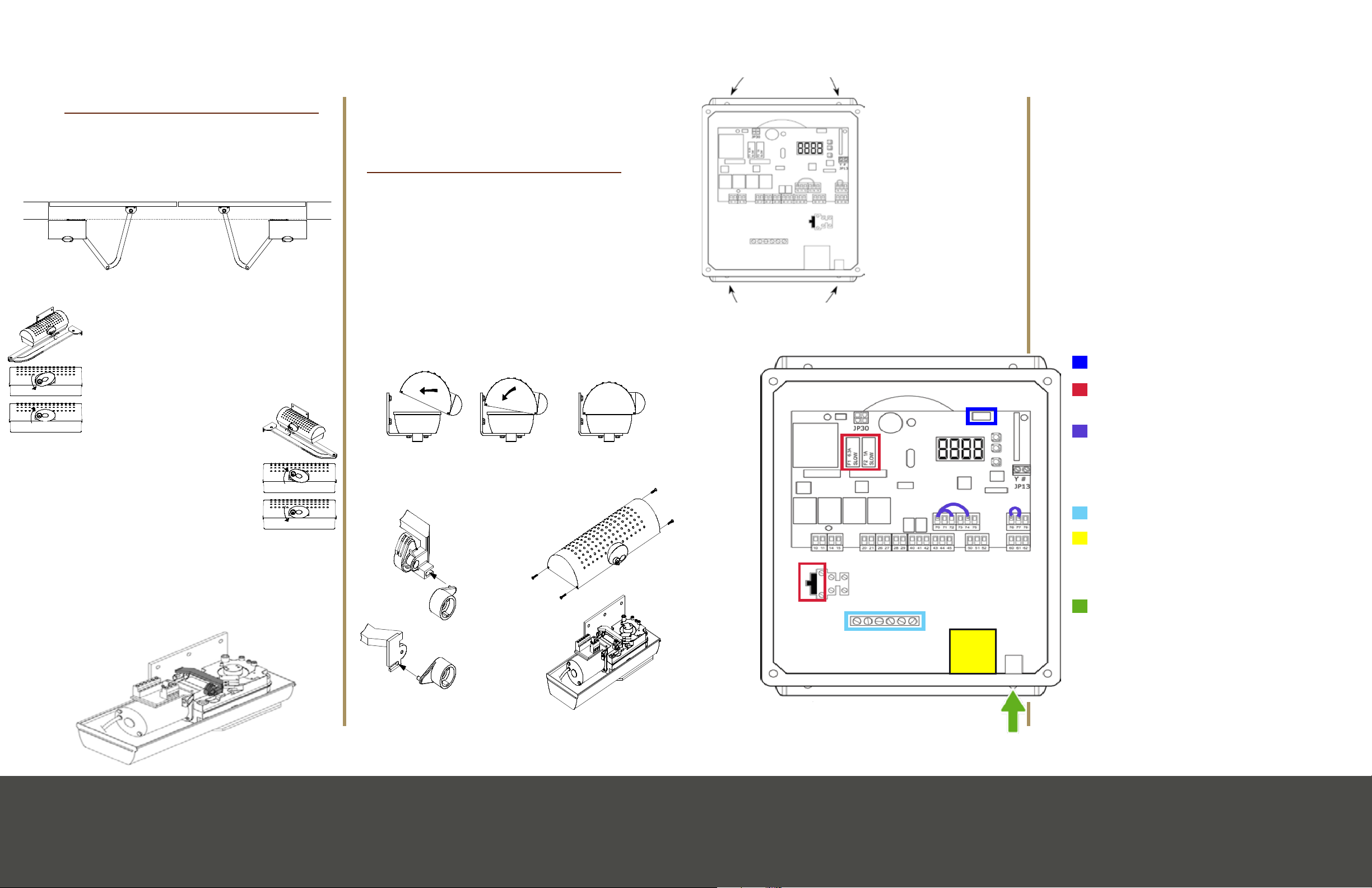
1.LocatethecontrolhousingcontainingtheLIBRAULRpanel.
2.Formounng,therearofthehousingmustbepredrilled.Refer
tog.5forthelocaonsoftheholestobedrilled.
3.Atthisme,planwhereyouwouldliketorunthewiringinto
thehousingandpredrillforstressreliefconnectors.Be careful
not to damage the panel when drilling into the housing! It is a
good idea to remove the panel while drilling.
4.Mountthehousingsecurely,usingeitherscrewsordrywall
anchors(notsupplied).Becarefulnottodamageanywiresor
componentsoftheboard.(See“TypicalSystemOverview”for
suggestedlocaonofthehousing)
Moun�ngtheControlHousing
Fig5.Mounnglocaons
Fig6.Stressreliefconnector
1.Locatethestressrelievingcordgrip.
2.Aachconnecngnut(F)togripbody(G).Tightensecurely
usingngerpressureonly.
3.Slipcompressionnut(H)overalengthof18/3(18Gauge,
3strand)motorwireandthreadwirethroughthe
assembledcordgrip.
4.Tightenthecompressionnut(H)withngerpressureonly.
5.Referto“MasterWiringDiagram”towirethemotortothe
LIBRAULRcontrolpanel.
6.Forbasicprogrammingsee“GeneralProgramming.”For
advancedparameters,pleaseseetheBFT“LIBRA‐UL‐R
Installa�on and User’s Manual”
WiringtheMotor
F
G
H
WIRE USE
min18/3wire*connecngmotorstocontrolpanel
min22/4wireconnecngRXphotoeyetocontrolpanel
min22/2wireconnecngTXphotoeyetocontrolpanel
*Use stranded wire. Increase gauge if motors more than 20’ from panel
TM
Franklin Autoswing Installation Manual
© 2012 Copyright Real Carriage Door Company, Inc
11
Installa�onofLimitSwitches
1.Installthelimitswitchreferncecamsas
showning.3.Installthefullcamontopof
themetalsha,theninstalltheringcamon
topofthefullcam.Donotfullyghtenthe
xingscrews.
2.Whenthedoorisfullyopen,rotatethe
correspondingcam(g.4),unlyouheara
‘click’indicangthelimitswitchhasbeen
depressed,thenlockitinposionby
ghteningtheappropriatescrews.Repeatfor
thefullyclosedposion.Referto“Manual
OperaonMode”tomanuallyswingthedoor.
3.Swingthedoorslowlytoitsopenandclose
posions,listeningtoseethatthe‘click’of
thelimitsswitchoccurswheredesired.Adjust
asnecessary.
Fig4.LimitSwitchfuncons
LEFTMOTOR
(viewedfrominside)
RIGHTMOTOR
(viewedfrominside)
CLOSELIMITCAM
OPENLIMITCAM
CLOSELIMIT
SWITCH
OPENLIMIT
SWITCH
OPENLIMITCAM
CLOSELIMITCAM
OPENLIMIT
SWITCH
CLOSELIMIT
SWITCH
Fig3.LimitSwitchinstallaon
FULLCAMRINGCAM
Franklin Autoswing Installation Manual
TM
10
© 2012 Copyright Real Carriage Door Company, Inc

Page 11SpecicationsPage 10 Igea Motor Installation Page 11Mounting the Control Unit
Mounting
the Control
Unit
1. Locate the control
housing containing the
Thalia UL panel.
2. At this time, plan where you would like to run the
wiring into the housing and predrill for stress-relief
connectors.
NOTE: Be careful not to damage the panel when
drilling into the housing! It is advisable to remove
the panel while drilling.
3. Mount the housing securely, using either screws
or drywall anchors (not supplied). Be careful not
to damage any wires or components of the board.
(See “Typical System Overview” for suggested
location of the housing).
Manual Operation Mode
In the case of power failure or operator malfunction,
manual operation mode can be carried out
by turning the external release knob with a
personalized key.
Left Door (as viewed from inside)
1. Turn key clockwise
2. Turn release knob counter-clockwise
3. Turn key back to keep in release position
4. Push/pull door slowly to open or close
5. Reverse steps to re-activate
auto-mode
Right Door (as viewed from
inside)
1. Turn key clockwise
2. Turn release knob clockwise
3. Turn key back to keep in release
position
4. Push/pull door slowly to open or
close
5. Reverse steps to re-activate auto-mode
Note: When working with limit switches, the key
cannot be used manually to release the motor. To
release, ip the black lever (pictured) and swing the
door. The lever must be held down while swinging
as it is spring loaded.
Motor Cover Install
1. Hold the cover over the motor, with the front
of the cover angled toward you. Rock the cover
rearward (g. 7) until the cover is seated. The cover
must be installed in this way so that the Manual
Operation cam engages properly with motor (g 8).
2. Test the manual release mechanism as
described in “Manual Operation Mode.”
NOTE: If your manual release does not work when
you turn the knob located on the motor cover then
you need to do some adjusting. Please visit our
website to download the instructions or give us a
call at 1-800-694-5977
ManualOperaonMode
NOTE:Whenworkingwithlimitswitches,the
keycannotbeusedtomanuallyreleasemotor.
Torelease,iptheblacklever(picturedat
right)andswingthedoor.Thelevermustbe
helddownwhileswingingasitisspringloaded.
RightMotorLeMotor
Inside
Outside
ForLEFTmotor(asviewedfrominside):
1.Turnkeyclockwise
2.Turnreleaseknobcounter‐clockwise
3.Turnkeybacktokeepinreleaseposi�on
4.Push/pulldoorslowlytoopenorclose
5.Reversestepstore‐ac�vateauto‐mode
ForRIGHTmotor(asviewedfrominside):
1.Turnkeyclockwise
2.Turnreleaseknobclockwise
3.Turnkeybacktokeepinreleaseposi�on
4.Push/pulldoorslowlytoopenorclose
5.Reversestepstore‐ac�vateauto‐mode
Inthecaseofpowerfailureoroperatormalfunc�on,manualopera�onmodecanbecarriedout
byturningtheexternalreleaseknobwithpersonalizedkey.
Franklin Autoswing Installation Manual
TM
6
© 2012 Copyright Real Carriage Door Company, Inc
ManualOperaonMode
NOTE:Whenworkingwithlimitswitches,the
keycannotbeusedtomanuallyreleasemotor.
Torelease,iptheblacklever(picturedat
right)andswingthedoor.Thelevermustbe
helddownwhileswingingasitisspringloaded.
RightMotor
LeMotor
Inside
Outside
ForLEFTmotor(asviewedfrominside):
1.Turnkeyclockwise
2.Turnreleaseknobcounter‐clockwise
3.Turnkeybacktokeepinreleaseposi�on
4.Push/pulldoorslowlytoopenorclose
5.Reversestepstore‐ac�vateauto‐mode
ForRIGHTmotor(asviewedfrominside):
1.Turnkeyclockwise
2.Turnreleaseknobclockwise
3.Turnkeybacktokeepinreleaseposi�on
4.Push/pulldoorslowlytoopenorclose
5.Reversestepstore‐ac�vateauto‐mode
Inthecaseofpowerfailureoroperatormalfunc�on,manualopera�onmodecanbecarriedout
byturningtheexternalreleaseknobwithpersonalizedkey.
Franklin Autoswing Installation Manual
TM
6
© 2012 Copyright Real Carriage Door Company, Inc
InstallingtheMotorCover
1.Holdthecoveroverthemotor,withthefrontofthecoverangledtowardyou.Rockthecoverrearward(g.7)un�l
thecoverisseated.ThecovermustbeinstalledinthiswaysothattheManualOpera�oncamengagesproperly
withmotor(g8).
2.Testthemanualreleasemechanismasdescribedin“ManualOpera�onMode.”
3.Fastenthecoverwiththe4screwsprovided(g.9).
Fig8.ManualOpera�onCams
Fig7.Sea�ngthecover
Fig9.Securingthecover
LEFTMOTORCAM
RIGHTMOTORCAM
Franklin Autoswing Installation Manual
TM
14
© 2012 Copyright Real Carriage Door Company, Inc
CONTROL UNIT SPECIFICA
TIONS
Wi Hub plug in location
Fuse locations
Jumper wires NOTE:
Once photo eyes are
wired in the jumper wire
from 70 + 72 MUST be
removed
Ground
UL alarm, NOTE: The
alarm will sound if the
force or photo eyes are
triggered twice in a row
Reset button. NOTE: If
the UL alarm is triggered
the unit will go into safety
mode, to reset the unit
you must press the button
on the underside of the
control unit.

Page 13SpecicationsPage 12 Wiring Simplied Page 13Wiring Simplied
Wiring Simplied
Motor 1 is the door that will open rst and close
last. For Single door application please only use
Motor 1 wiring. Connect Motor wires to motor
output terminal 10 and 11, and the
limit input at terminal 42.
Motor 2 is the door that will open last and close
rst. For dual motor installations this will be your
second motor. Motor 2 output terminals are 14 and
15, and the limit input is terminal 43
Warning! Jumper
wire from 70 + 72
must be removed
once photo eyes
are wired into the
control board or
else you will re-
ceive an Error01
code after the
Autoset.
For assembly instructions see page
21. For programming please see
page 15 or 22.
The wired wall button needs
additional programming to function.
If this step is missed the button will
only activate open and will ot close
the doors.
Wired Wall Button

Page 14 Specications Page 15Specications
(Steps 1-3) or press [OK] to end
Programming after the completed Autoset
If the doors are in the closed position after the
Autoset is complete you can move on to Step 2.
If they end in the open position, then you need to
adjust your programming and follow the instruction
for step 2.
1. To get into the programming menu press [OK]
twice quickly
• “HALT” will appear on the display
• Press [OK] twice again
• “PARAM” will appear on the display
• Use [–] button to scroll to “LOGIC”
• Press [OK]
• Use [–] button until you see “OPEN IN OTHER
DIRECT”
• Press [OK]
• Adjust the value to 1
• Press [OK]
• Press [+] and [–] at same time twice to exit
menu
• Test doors again
Continuous Force Learning Mode
2. Go into “LOGIC” menu again press [OK] (if you
did not complete Step 1 then press [OK] twice
quickly, “HALT” will display and press [OK]
twice again)
• Scroll till you see “ICE”
• Press [OK]
• Change value to 1
• Press [OK]. This continues force learning
mode on every cycle.
• Scroll down with [–] button until you see “SAFE
1” (this is in “LOGIC” too)
• Press [OK]
• Change value to 5 to ignore photo sensors on
open
• Press [OK]
3. Programming for Wired Wall Button
4. Scroll down with [–] button until you see “IC 1”
• Press [OK]
• Adjust the value to 000
• Press [OK]
• Press [+] and [–] at the same time to exit the
menu (you will need to do this multiple times to
completely exit the menu)
Troubleshooting
Doors close instead of open when photo eyes are
interrupted
• If you are having trouble with the doors
reversing the incorrect direction when the photo
beam is interrupted, then you can do one of
these two things:
1. Go to the logic menu and change the direction
2. Swap the motor power wires (#10 & #11
and #14 & #15)
Motors are trying to open the wrong direction
• If the motors are trying to pull in instead of
out, then the polarity is incorrect; and you want
to double check your wiring and make sure it
matches the wiring simplied diagram.
Wrong door is opening rst
• If the wrong door is opening rst then you have
Autoset Programming
for Quick Setup
The Franklin Autoswing comes “out of the box”
with preprogrammed defaults that allow the unit
to function with just a small amount of initial setup
programming.
NOTE: Make sure the doors are in the closed
position before running the Autoset.
1. Press the [OK] button once
• The display will read “LANG” (language)
followed by “ITA” (Italian)
• Scroll down using the minus [-] button until you
see “ENG” (English) displayed
• Then press the [OK] button
2. The word “TYPE” will be displayed briey
• Press the minus [-] button until “IGEA” is
displayed
• Then press [OK]
3. The next screen will display “N. MOT” (Number
of Motors)
• Scroll down with the minus [-] button until “2” is
displayed
• Press [OK]
Note: if only installing one motor, choose “1” then
press OK
4. “DR” (Direction) will now be displayed for a
moment followed by “INT” (interior)
• Select “INT” and press [OK]
5. Next “PRESET” will be displayed, followed
immediately by “AR” (Automatic Residential)
• Scroll down to “SR” (Semi-Automatic
Residential). This allows the doors to work like a
typical garage door
• Press [OK]
Note: AR will cause the doors to automatically close
on their own, SR requires you to press a button to
close.
6. After selecting your preset, the screen will
display “PROG” (programming) for a few
seconds
• The screen will then display “AUTOSET”
• Be sure the path of the doors is clear of trafc
and obstructions. Be aware that the doors will
run at full torque during the process
• Press [OK] when ready
• The motors will run full open and close cycles
more than once (to learn the force required to
open and close the doors)
• “OK” will be displayed
• Press the [OK] button to continue
Note: If the motors do not run and/or “KO” is
displayed press [OK] to display error code. Check all
wiring, fuses, photo eye alignment and wiring.
Programming the Remotes
1. The display will read “MEM. REMOTES”
(Memorized Remotes)
• Immediately followed by “HIDDEN BUTTON”
2. Firmly press and hold the top two buttons on
your remote (this is the hidden button)
• When the screen reads “RELEASE”, release the
two buttons
3. The screen will then read “DESIRED BUTTON”
• Press and release the button you wish to
operate the doors with
4. The screen will display “HIDDEN BUTTON”
again
• You can repeat the remote leaning process

Page 17SpecicationsPage 16 Programming Features Page 17Programming Features
Range Value
for IC1 and IC2
Funcon Descripon
002 OPEN Open only.
Used with
[open] but-
tons, free exit
and/or open
only devices
003 CLOSE Close only.
Used with
[close] buons
and closing
loop detectors
004 PED Pedestrian
opening.
Parally open
Motor 1 only
005 TIMER Hold open
input
006 TIMER PED Holds parally
open Motor 1
Accessory Connections
24-volt accessories and peripherals
can be powered to terminals 50 and
51
Terminal Name Descripon
50 -24V Accessory
power nega-
ve common
51 +24V Accessory
power posive
52 +24V -Safe Posive power
when door is
not closed
Auxiliary
Outputs
The Thalia
board has
two auxiliary
outputs.
• The rst
(20 and
21) is a 24-volt, courtesy light output that will
activate upon activation of the door and will
remain on for 90 seconds once the door is
closed
• The second output labeled “Aux 3” (26 and
27) is a defaulted as a second channel radio
receiver output. This can be programmed to
perform any of the following functions under
“Logic” menu:
Range Value
for “Aux 3”
Function Description
0 2nd channel
receiver output
Output
activate when
transmitter
activates the
2nd channel
1 Door open light Output activate
when door is
not closed.
Flashes while
closing
2 Courtesy light Output activate
during and for
90 seconds
after operation
3 Door not
closed
Output activate
until close limit
is reached
4Start of cycle Output activate
for 1 second at
the beginning
of each cycle
the wrong motor wired into 10, 11, and 42, and
will need to switch the motor wiring (the 2nd
door is 14, 15, and 43).
• If you have checked these two things and your
doors are not moving, then check to make sure
your limit stops (also known as cams) are not
reversed (see page 6).
• It is important to note that the left door is setup
as the bottom cam is open and the top is close,
whereas the right motor is top is open and
bottom is close.
Default/Factory Setting
• If you ever need to revert to factory settings and
start programming over again, please go into
the menu on your control board press the plus
or minus button until it reads default and then
press the OK button.
Note: You know your doors are properly setup after
you nish the AUTOSET, the doors rest in the closed
position and the screen display reads “c.c..”
Programming Features
The Thalia control board has many features and
programmable options. Please reference page 32-
35 for the full programming menu.
Navigating the Menu:
1. Press [OK] twice to get into the programming
menu
• “HALT” will appear on the display
2. Press [OK] twice again
• “PARAM” will appear on the display
3. Once you reach the desired menu option using
the [+] or [-] buttons
• Press [OK]
4. Scroll until you reach the selection that needs
programming
• Press [OK]
5. Adjust the value as needed
• Press [OK]
6. To exit the menu press [+] and [-] once or twice
(twice completely exits out of the programming
menu)
Command Inputs
The Thalia control provides two command inputs
(“IC1” and “IC2”).
Terminal Name Descrip-
on
Default
60 COM Command
posive
common
common
61 IC 1 Command
Input 1
START
62 IC 2 Command
Input 2
PED
Command input 1 and 2 can be re-programmed to
perform any of the following instructions:
Range Value
for IC1 and IC2
Funcon Descripon
001 START Cycles be-
tween open,
stop and close.
Normally used
with single
push-buons
and radio
receivers

Page 19SpecicationsPage 18 Programming Features Page 19Programming Features
Termi-
nal
Name Descrip-
on
Default Notes
76 COM Safety
posive
com-
mon
Com-
mon
77 SAFE 3 Safety
input
#3
Pro-
gram-
mable
input
78 FAULT 3 Safety
input
#3
FAULT Re-
quires
oppo-
site re-
lay state
from
SAFE 3
SAFE 2 and SAFE 3 can be programmed to perform
any of the following instructions under the “LOGIC”
sub-menu:
Range Value Funcon Descripon
000 PHOT System reacts
to the input in
both opening
(stops) and
closing (revers-
es) cycles
001 PHOT TEST Same as
above. Re-
quires the de-
vice to super-
vised (FAULT
acve)
002 PHOT OP System reacts
to the input
only during
the opening
cycle (stops)
Range Value Funcon Descripon
003 PHOT OP TEST Same as
above. Re-
quires the
device to be
supervised
(FAULT acve)
004 PHOT CL System reacts
to the input
only during the
closing cycle
(reverses)
005 PHOTO CL
TEST
Same as
above. Re-
quires the
device to be
supervised
(FAULT acve)
006 BAR Safety edge in-
put. It reacts in
both opening
and closing. It
stops and par-
ally reverses
007 BAR TEST Same as
above. Re-
quires the
device to be
supervised
(FAULT acve)
008 BAR 8K2 Safety edge
input with
EOL resistor
as supervision
method. Only
acve on SAFE
2
009 BAR OP Safety edge
input. During
opening it
stops and par-
ally reverses.
During closing
it stops
Range Value
for “Aux 3”
Function Description
5 Door open
alarm
Output activate
if door is help
open for more
than double
the timer to
close time
6 Door running Output active
while motors
are powered
7Solenoid lock Output
active for 2
seconds at the
beginning of
open cycle
8 Magnetic Lock Output active
when door is
closed
Safety Devices
The Thalia board provides:
• One STOP command input
• One obstruction sensing device input that
reacts to the input in both opening (stops) and
closing (reverses) cycles. This is UL 325-2016
compatible with it’s SAFE 1 with its mandatory
supervision
circuit input
FAULT 1. SAFE
1, 001 PHOT
TEST (default
setting) and
005 PHOT CL
TEST reacts
to input during
closing only
• Two
programmable
obstruction
sending
devices input
for SAFE 2
and SAFE 3, both are provided with optional
supervision circuit FAULT 2 and FAULT 3
All 3 safety inputs are normally closed (N.C.)
contacts. All the FAULT inputs are normally open
(N.O.) contacts.
Termi-
nal
Name Descrip-
on
Default Notes
70 COM Safety
posive
com-
mon
Com-
mon
71 STOP Stop
com-
mand
STOP Over-
rides all
other
com-
mands
72 SAFE 1 Safety
input
#1
PHOT Stops
oper-
ators
during
open-
ing,
reverses
on clos-
ing
73 FAULT 1 Super-
visory
circuit
for SAFE
1
FAULT Re-
quires
oppo-
site re-
lay state
from
SAFE 1
74 SAFE 2 Safety
input
#2
006-
BAR
Pro-
gram-
mable
input
75 FAULT 2 Super-
visory
circuit
for SAFE
2
FAULT Re-
quires
oppo-
site re-
lay state
from
SAFE 2

Page 21SpecicationsPage 20 Programming Features Page 21Wired Wall Button
Installing Wired Wall
Button
1. Insert a small
slotted screwdriver
laterally between the
button frame (1) and
button switch (2) and
carefully pry out the
button switch.
2. Unscrew both screws (1).
3. Insert a small slotted screwdriver into one of
the notches between the button frame (1) and
button base (2) and carefully pry out the button
base.
4. Mounting to a wooden subsurface:
• Hold the button base (1) on the wall and mark the
mounting points.
• Screw in two at head wood screws (2) and
tighten rmly by hand.
5. Mounting to masonry:
• • Hold the button base (1) on the wall and mark
the mounting points.
!WARNING! Risk of injury from ying chips when
drilling. Drilling chips can get into the eyes and
injure them.
• Using a drill with a masonry bit, drill two holes and
insert two suitable anchor ttings.
• Screw in two at head wood screws (3) and
tighten rmly by hand.
6. Connection in the button:
• The cable can fed in from above or below
• Strip a small of insulation from the wire ends of
the two-wire cable 2x22 AWG (1) by about 3/8”
• Unscrew the screws (2) and (3) lightly
• Insert both stripped wire ends into the terminal
Range Value Funcon Descripon
010 BAR OP TEST Same as
above. Re-
quires device
to be super-
vised (FAULT
acve)
011 BAR OP 8K2 Safety edge
with EOL resis-
tor as supervi-
sion method.
During open-
ing it stops
and parally
reverses.
During closing
it stops. Acve
only on SAFE 2
012 BAR CL Safety edge
input. During
closing it stops
and paral-
ly reverses.
During open-
ing it stops.
013 BAR CL TEST Same as
above. Re-
quires the
device to be
supervised
(FAULT acve)
014 BAR CL 8K2 Safety edge
input with
EOL resistor
as supervi-
sion method.
During clos-
ing it stops
and parally
reverses.
During closing
it stops. Acve
only on SAFE 2
Range Value Funcon Descripon
015 SHADOW Safety loop in-
put. If the con-
tact is closed,
it prevents any
movement
of the door
leaves when
the doors are
open (Value 0
on the LOGIC
SHADOW)
or when the
doors are
both open and
closed (Value
1 of the LOGIC
SHADOW)

Page 23SpecicationsPage 22 Wired Wall Button Page 23Programming Remotes
• “PARAM” will appear on the display
3. Press the [–] button one time
• The display will show “LOGIC”
4. Press the [OK] button
• “TCA” will appear on the display
5. Press the [-] button until you see “IC 1”
• Press [OK]
6. Adjust the “IC 1” to value of 000
• Press [OK]
7. Press [+] and [–] at the same time to exit the
menu
Programming
Additional Remotes
1. To get into the programming menu press [OK]
twice quickly
• “HALT” will appear on the display
2. Press [OK] twice again
• “PARAM” will appear on the display
3. Use [–] button to scroll to “RADIO”
• Press [OK]
• The display will read “ADD START”
• Press [OK]
4. “HIDDEN BUTTON” will appear on display
• Firmly press and hold the top two buttons on
your remote (this is the hidden button)
5. When the screen reads “RELEASE”, release the
two buttons
6. The screen will then read “DESIRED BUTTON”
• Press and release the button you wish to
operate the doors with
7. The screen will display “HIDDEN BUTTON”
again
8. You can repeat the remote leaning process, or
press [OK] to end
NOTE: On 4-button remotes, the hidden button
is activated by pressing the two forward buttons
closest to the LED at the top of the remote.
(polarity proof connection)
• Tighten both screws (2) and (3)
• Using pliers, break out the cable pass through
(1) or (2) in the button frame (3)
• Press the button frame (3) onto the button base
(4) until it locks into place
• Observe the position of the cable in pass
through (1)
• Unscrew the screws (2) and (3) slightly
• Insert both stripped wire ends into terminals 60
and 61 (polarity proof connection)
• Tighten both screws (5) rmly by hand
7. Clip on the button switch (1). Insert a pin (2) left
or right and lock the pin on the other side into
place.
8. If wire is not to be run in the wall, attach using
the staples provided.
9. Strip insulation back on the ends of the wire
that are to be inserted into the terminal inside
the controller housing.
10. Insert wires into terminal #’s 15 and 16 and
tighten screws securely. Note: polarity is not
observed.
Programming the Wired Wall Button
The wall button requires that the input command
to be reprogrammed on the control board to
open and close the doors (please see page 13 on
programming menu for reference). If you do not
program the control board the wall button will only
open the doors.
To change the default setting of OPEN to a START
input please follow these steps:
1. On the control board please press [OK] twice
quickly
• “HALT” will appear on the display
2. Press [OK] twice again

Page 25SpecicationsPage 24 Optional Accessories Page 25Homelink Programming
Homelink
Programming
For programming troubleshooting please see out
Homelink troubleshooting guide, it can be found on
www.realslidinghardware.com under Tech Info.
Transmitter Individualization:
• Open up the transmitter by prying on corner as
illustrated
• Change the transmitter code by moving the
switches on the dip-switch bank.
• Carefully close transmitter by snapping
enclosure back in place.
Transmitter Programming:
• Open the transmitter by prying on corner as
illustrated
• Change the transmitter code by moving the
switches on the dip-switch bank.
• Carefully close transmitter by snapping
enclosure back in place.
Receiver Memory Deletion:
• Press and hold P1
Optional Accessories
Wireless Outdoor Keypad
With an outdoor keypad you enjoy secure exterior
access to your doors without a remote. Operates up
to 10 doors.
Wireless Wall Button
This upgraded wall button is wireless, so no wiring
is necessary for installation. Operates up to 4 doors.
ECOSOL Solar Power
Get your garage door off the grid with Ecosol solar
conversion. Allows up to 3 weeks of residential use
without sunshine. Optional accessory can charge
Battery Backup
Be prepared for unexpected power outages with a
battery backup. Dimensions 7.75” x 9.25” x 3.75”.
Battery Backup powers one Franklin system only.
HOMELINK Compatibility
Toss out your hand-held remote controls and
operate your garage door system directly from your
car with the Homelink compatibility option.
Extended Range Antenna
Use as a signal booster for long range operation
or thick masonry walls. (Not required for normal
operation.)
Wi-Fi Hub
Operate your openers from an app on your smart
from anywhere! This Wi-Fi Hub connects your
control unit to your Wi-Fi, allowing remote access
for up to 5 users. Have access to system errors,
geolocating, and program opening scenarios!

Page 27SpecicationsPage 26 Wireless Wall Button Page 27Outdoor Wireless Keypad
Outdoor Wireless
Keypad
• Each step has a 20 second timeout period, if
you do go past the timeout allotment then you
will need to start back at the beginning.
• You cannot use passcodes with all the same
numbers, for example [1] [1] [1] [1]
• During use if an incorrect passcode has been
entered in after 3 consecutive tries the keypad
will stop for 90 seconds before you can
continue
• The outdoor keypad can work with up to
10 openings and therefor has 10 channels
available
Programming the Keypad to the Thalia Board
Each opener needs its own channel to operate.
Opening 1 is Channel 1 and Opening 2 is Channel 2
and so on. The default code per each channel is the
channel number. For example, Channel 1 is [1] [1] [1]
[1] and Channel 5 is [5] [5] [5] [5].
1. Press and hold the [ON]
button on the keypad until the red
LED light comes on
• Press [1] [1] [1] [1]
• Press [ON]
• Red LED light will blink
2. On your control unit’s control board press [OK]
four times
• Press [-] until the display reads “rAdio”
• Press [OK]
• The display will read “Add StArt”
• Press [OK]
3. Press [ON] on the keypad
4. Green LED will blink twice
5. Wait 5 seconds
Changing the default code for Channels
1. To change the default code press and hold [ON]
button on the keypad
• Make sure red LED light is on
2. Press [1] [1] [1] [1]
• Press [OK]
• Red LED light will be xed and green LED will
blink
3. Enter the desired 4-digit code sequence
• Press [OK]
• Red LED light will be xed and green LED will
blink
4. Repeat step #3 to conrm new code
5. Green LED light will be xed
Additional Codes
1. Press and hold the [ON] button on the keypad
until the red LED light is on
2. Press [1] [2] [3] [4]
• Press [OK]
• Red LED light will be xed and green LED will
blink
3. Enter the current Channel 1 passcode
• Press [OK]
• Red LED light will be xed and green LED will
blink
4. Enter the desired 4-digit code sequence
• WITHOUT RELEASING P1, when the LED lights
up, press & hold P2 for 10 secs.
• Release both buttons. LED will ash 6 times
indicating memory deletion.
Programming to the Thalia Board
1. The Homelink receiver has two channels; the
blue and yellow are Ch.1, and green and orange
are Ch.2. The power supply is black and red.
• Black goes to 50
• Red to 51
• Blue to 60
• Yellow to 61
2. The green and orange are not needed unless
you want to use Ch.2, which can be used for
pedestrian command. If you do need Ch.2:
• Orange goes into 60
• Green into 62
3. Lastly be sure to program IC1 value to 000 on
your control board for Ch.1.
• On the control board please press [OK] twice
quickly
• “HALT” will appear on the display
4. Press [OK] twice again
• “PARAM” will appear on the display
5. Press the [–] button one time and the display
show “LOGIC”
6. Press the [OK] button
• “TCA” will appear on the display
7. Press the [-] button until you see “IC 1”
• Adjust the “IC 1” to value of 000
8. Press [OK]
9. Press [+] and [–] at the same time to exit the
menu
Wireless Wall Button
Note: Please see manufacturer instructions for
assembly
1. Press [“OK”] button four times to get into the
menu system
• Scroll with minus button [-] down to “rAdio”
• Press [“OK”]
2. The display will read “Add StArt”
• Press [“OK”]
• The display will read “hIddEn bUtton”
3. Note: The hidden button is the top two buttons
on the wall button
• Press top left button (channel one) and top right
button (channel two)
4. Press and hold the hidden button on the wall
button until the display reads “rELEASE”
5. Let go of both buttons and press the “DESIRED
BUTTON” one time.
6. Programming is now complete

Page 29SpecicationsPage 28 Outdoor Wireless Keypad Page 29Wi-Fi Hub
Wi-Fi Hub
Programming
Wi-Fi Hub Specications
Ambient Conditions
Minimum
-20 degrees Celsius or
-4 degrees Fahrenheit
Ambient Conditions
Maximum
50 degrees Celsius or
122 degrees Fahrenheit
Band 2400 - 2483.5 MHz
Dimensions 42x29 (H x L) mm
Wi-Fi 802.11 : b/g/n. Bit rate:
72.2 Mbps. Security:
OPEN, WPA2/ WPA
Personal and WEP
The Wi-Fi
hub allows
your Franklin
Autoswing to connect
to Wi-Fi so that way you
can operate the openers
with an app on your
smart phone. Before you
proceed you must have the
following:
• Wi-Fi Hub accessory
• Thalia model Franklin (it will say
Thalia in the control box or it has grey control
unit housing instead of black)
• Have strong Wi-Fi connection where the control
unit is located
• Own a smart phone
Installation Steps
With the control board OFF, insert the Wi-Fi Hub to
the appropriate location on
the control board
7. Turn the control board
ON
8. Download the “U-Control”
app from your app store
9. Start up the “U-Control”
app
• Click on “Register”
• Enter in your details (Fig. A)
10. Once your email address
and password are
entered click “Register”
(Fig. B)
• If you have already
registered then you will
select “Access” and
continue
11. Open your Wi-Fi
connections on your
phone (Fig. C)
• Connect to the Wi-
Fi signal of your
Wi-Fi Hub which is
identied as BeBA-WI-
• Press [OK]
• Red LED light will be xed and green LED will
blink
5. Repeat step #4 to conrm new code
6. Green LED light will be xed
Changing a current passcode
1. Press and hold the [ON] button on the keypad
until the red LED light is on
2. Enter current passcode
• Press [OK]
• Red LED light will be xed while the green LED
light blinks
3. Enter the desired 4-digit code sequence
• Press [OK]
• Red and green LED should be xed
4. Repeat step #3 to conrm new code
5. Green LED light will be xed
Regular Use of outdoor Keypad
1. Press [ON]
2. Enter in passcode
• Press [OK]
• Green LED light will be xed
3. Doors will open
Outdoor Keypad Reset
1. Remove batteries from the keypad
2. Remove the jumper from one leg as shown in
picture and insert jumper grabbing both legs
3. Insert batteries and wait for unit to stop
beeping and ashing
4. Once these alerts stop, remove the batteries
5. Remove the jumper off both legs and reinsert
onto one leg
6. Insert batteries and start over with instructions

Page 31SpecicationsPage 30 Wi-Fi Hub Page 31Programming Menu
Full Programming
Menu for the alia
Control Board
Navigating the Controls
Press [OK] twice to get into the programming menu
“HALT” will appear on the display
Press [OK] twice again
“PARAM” will appear on the display
Once you reach the desired menu option using the
[+] or [-] buttons
Press [OK]
Scroll until you reach the selection that needs
programming
Press [OK]
Adjust the value as needed
Press [OK]
To exit the menu press [+] and [-] once or twice
(twice completely exits out of the programming
menu)
FI_00xxxxxxxxxx (Fig. D)
• Enter in the
password
“BEBAWIFI” (Fig.
E)
• Click connect
12. Return to the
App
• Click on
“Proceed” (Fig.
F)
13. Fill in the
required elds
(Fig. G)
• Click on “Next”
14. Connect to the Wi-Fi
network on your router (Fig. H)
• Enter the name of your Wi-
Fi network
• Enter the password for
your Wi-Fi network
• Click “Done”
15. Conrm
pairing by click
“Proceed” (Fig. I)
• Conrm
successful pairing by
clicking “Ok” (Fig. J)
Note: Any incorrect
Wi-Fi network data
entry makes it necessary to reset the WI-FI HUB,
pressing the key on the card for at least 5 seconds,
to make it visible again to the phone and return to
step 6.
16. The U-Control app conguration is now
complete Now it is possible to:
• Open and close your doors (Fig. K)
• Share the app with other members (Fig. L)
• Create scenarios
• Activate geolocating (Fig. M)

Page 33SpecicationsPage 32 Programming Menu Page 33Programming Menu
Main Selec-
tion
Description De-
fault
Range
LOGIC> STEP-
BY-STEP
MOVE-
MENT
Determines
how the
system reacts
when a START
command
is received
during opera-
tion
0 0-2
LOGIC> SHAD-
OW
Conguration
of safety loop
input terminal
74 or 77 when
SAFE 2 or
SAFE 3 are set
as 015 (SHAD-
OW)
0 0-1
LOGIC> SAFE 3* Conguration
of safety input
terminal 76.
Defaulted
as SHADOW
(Safety loop)
15 0-15
LOGIC> PRE-
ALARM
Gate running
output (AUX
value=6)
closes 3 sec.
before gate
movement
0=OFF / 1=ON
0 0-1
LOGIC> HOLD-
TO-RUN
Requires con-
tinuous OPEN
or CLOSE
command
input for gate
to operate.
0=OFF / 1=ON
0 0-2
LOGIC> IBL
OPEN
Ignores START
input during
the opening
cycle
0 0-1
Main Selec-
tion
Description De-
fault
Range
LOGIC> IBL TCA Ignores the
START input
while counting
down for auto-
matic closing
0=OFF / 1=ON
0 0-1
LOGIC> IBL
CLOSE
Ignores the
START input
during the
closing cycle.
O=OFF / 1=ON
0 0-1
LOGIC> RAM
BLOW C.
OP
Pushes gate
against physi-
cal stop before
opening
0 0-1
LOGIC> RAM
BLOW C.
CL
Pushes gate
against physi-
cal stop before
closing
0 0-1
LOGIC> BLOC
PERSIST
Hourly push
against physi-
cal stop
0 0-1
LOGIC> PRESS
SWC
Pushes gate
against physi-
cal stop for .5
seconds after
close limit has
been reacted
0 0-1
LOGIC> ICE Continuous
force learning
on every oper-
ation
0 0-1
LOGIC> OPEN IN
OTHER
DIRECT.
0 - Pull to open
/ 1= Push to
open
0 0-1
Main Selec-
tion
Description De-
fault
Range
PARAM> OPEN
DELAY
TIME
Motor 2 open-
ing delay in
seconds
10-10
PARAM> CLS
DELAY
TIME
Motor 1 clos-
ing delay in
seconds
10-10
PARAM> TCA Auto-close
time ad-
justment in
seconds
10 1-180
PARAM> TRF.
LGHT.
CLR.T
Trafc zone
clear time
adjustment in
seconds
40 1-180
PARAM> OP.DIST.
SLOWD
Slowdown
starting
distance
from end of
open travel
expressed in
percentage
10 0-50
PARAM> CL.DIST.
SLOWD
Slowdown
starting
distance
from end of
close travel
expressed in
percentage
10 0-50
PARAM> DIST.
DECEL
Slowdown
starting
distance from
end of open
and close trav-
el expressed in
percentage
15 0-50
Main Selec-
tion
Description De-
fault
Range
PARAM> OP.
FORCE
Percentage of
opening force
exerted over
the AUTOSET
value before
obstruction is
sensed
50 1-99
PARAM> CLS.
FORCE
Percentage of
closing force
exerted over
the AUTOSET
value before
obstruction is
sensed
50 1-99
PARAM> OP
SPEED
Motor opening
speed ex-
pressed in per-
centage
99 15-99
PARAM> CL
SPEED
Motor clos-
ing speed
expressed in
percentage
99 15-99
PARAM> SLOW
SPEED
Slowdown
speed ex-
pressed in
percentage
from maxi-
mum speed
25 15-99
LOGIC> MOTOR
TYPE
1=Eli 250;
2=Phobos BT
0
LOGIC> TCA Timer to Close
Automatically.
0=OFF / 1=ON
0 0-1
LOGIC> FAS T
CLS.
Closes when
sensors are
cleared. 0=OFF
/ 1=ON
0 0-1

Page 35SpecicationsPage 34 Programming Menu Page 35Safety Devices/Detectors
Main Selec-
tion
Description De-
fault
Range
LOGIC> TRAFFIC
LIGHT
PRE-
FLASH-
ING
Ignores the
START input
during the
closing cycle.
O=OFF / 1=ON
0 0-1
LOGIC> TRAFFIC
LIGHT
RED
LAMP
ALWAYS
ON
Red light
remains on
when gate is
closed. 0=0FF
/ 1=ON
0 0-1
RADIO> ADD
START
Learns
transmitter
button as
START com-
mand
- -
RADIO> ADD
2CH
Learns trans-
mitter button
as 2nd chan-
nel
- -
RADIO> ERASE
64
Erase com-
plete memory
- -
RADIO> COD RX Show receiver
ID code
- -
RADIO> WK W LINK. - -
Additional Safety
Devices
Real Carriage Door and Sliding Hardware is proud
to be able to offer extra safety devices to meet the
demands of your project. Each device is different
and is suited for different applications and will
need to be special ordered. The manufacturer of
the openers will need to work with us directly to
pick which option ts your specic application.
Examples of these extra safety devices include exit
probes, mag locks, electronic drop pins, and safety
loops.
We do not provide instructions for these extra
safety devices and will need to be sourced
directly from manufacturer. There may need to be
additional programming done to the control board,
please conrm before the doors are used for safety
purposes.
• This may include having the doors simply stop
when the photo eyes are triggered instead of
reverse. Once the beam is cleared the doors
will then continue to open or reverse to open.
To do this you would set SAFE2 as 000 (if using
terminals 70 + 74).
Main Selec-
tion
Description De-
fault
Range
LOGIC> SAFE 1 * Conguration
of safety input
terminal 72.
Defaulted as
Phot Test (Ob-
struction)
11 & 5
LOGIC> SAFE 2 * Conguration
of safety input
terminal 74.
Defaulted as
BAR (Safety
Edge)
60-15
LOGIC> SAFE 3 * Conguration
of safety input
terminal 75.
Defaulted
as SHADOW
(Safety Loop)
15 0-15
LOGIC> IC 1 * Conguration
of command
input terminal
61. Defaulted
as Start E
0 0-6
LOGIC> IC 2 * Conguration
of command
input terminal
62. Defaulted
as Ped (Partial
open)
4 0-6
LOGIC> AUX 3 * Conguration
of auxiliary
output termi-
nals 26 & 27.
Defaulted as
2nd channel
contacts
0 0-8
LOGIC> FIXED
CODE
Rolling code
defeat. 0 =
rolling code
1 =
xed
code
0
Main Selec-
tion
Description De-
fault
Range
LOGIC> RADIO
PROG
Quick remote
programming.
0=disabled /
1-=enabled
10-1
LOGIC> SERIAL
MODE
0 =
Slave
unit / 1 =
Master
unit
0 0-1
LOGIC> AD-
DRESS
Unit’s network
identication
number
0 0-127
LOGIC> EXPI 1 * Conguration
of Expansion
board input 1.
Defaulted as
Start com-
mand
10-14
LOGIC> EXPI 2 * Conguration
of Expansion
board input 2.
Defaulted as
Start com-
mand
0 0-10
LOGIC> EXP0 1 * Conguration
of Expansion
board output
1. Defaulted
as Trafc light
control
90-9
LOGIC> EXPO
2 *
Ignores the
START input
while counting
down for auto-
matic closing
0=OFF / 1=ON
90-9

Page 37SpecicationsPage 36 Battery Backup Page 37Arched Doors
Arched Door
Applications
With some arched doorways, proper motor
positioning can be a little challenging. Door
construction, radius, and overall width can all affect
motor placement. Below is a guide designed to
assist you in mounting while allowing for proper
geometry of the opener system’s articulated lever
arm.
• Optimal placement for the Igea motor is about
8-1/2” to 9” out into the opening on the header.
This provides ideal attachment to reach the
door
Mounting Instructions Option 1
1. Fashion a plywood or cardboard disk that you
can use as a template. The disk should be 8” in
diameter, with a 1-7/8” diameter hole cut out of
the center.
2. Set the disk on your assembled lever arm as
show below. You will not need the motor or
base plate. With your door leaf in the fully open
position (approx 105 degrees), move the disk
along the wall and door coupling along the
door until you achieve the dimensions at right.
For best results, the
straight leg of the
lever arm should be
as close as possible
to the arched jamb
(1/2” min).
3. Drop the motor
into the base plate
and hold on wall at
anticipated mounting
location. Dry t
the lever arm and
adjust height of
entire assembly as
necessary for proper arm clearance when fully
open.
4. Mark the height of base plate. Mount the plate
as described in “Installing the Motor,” and
continue with normal installation.
Mounting instructions Option 2
1. Position the door in open position and steady it
2. While up on a platform/ladder, hold the motor
position with the arms
3. Hold the motor up in the approximate position
while swinging arm out to reach door in the
open position
4. If position and movement work well, mark
motor location
5. Bolt the motor temporarily to the marked
position
6. Then test reach (open position) and the
positioning (closed position)
7. If the motor arms clear the jamb, and the door
moves as intended then you can continue with
motor installation
NOTE: Securely mounting the base plate is very
important. If needed, drill additional mounting
holes to afx the plate directly to the jamb. It is
also preferable that the arm be positioned past the
door’s center point or roughly 2/3rds of the door
width.
Battery Backup
1. Secure the battery housing to solid blocking
using screws or lag bolts (not provided)
2. Wire the batteries into the terminal strip using
14ga. (minimum) wire in series as shown below
• Take care to observe polarity
3. Run a wire from terminal 3 on the battery
controller board
• Splice it into the two Line (black) wires feeding
from the transformer to the opener controller
board (bottom two wires on JP30)
4. Split the two neutral (white or grey) wires
running from the transformer to the controller
board (top two wires on JP30)
5. Run a wire from terminal 4 on the battery
controller board to the transformer side of the
neutral wire pair
• Then run a wire from terminal 5 on the battery
controller board to the neutral wire end
attached to the opener controller board
AppendixD
(Alterna�veMoun�ng)
1.Fashionaplywoodorcardboarddiskthatyoucanuse
asatemplate.Thediskshouldbe8”indiameter,with
a1‐7/8”diameterholecutoutofthecenter.
2.Setthediskonyourassembledleverarmasshow
below.Youwillnotneedthemotororbaseplate.With
yourdoorleafinthefullyopenposi�on(approx105
degrees),movethediskalongthewallanddoor
couplingalongthedoorun�lyouachievethe
dimensionsatright.Forbestresults,thestraightlegof
theleverarmshouldbeascloseaspossibletothe
archedjamb(1/2”min).
3.Markthecenterpointofthebracketonthedoorand
thetangentpointofdiskonthewall.
4.Dropthemotorintothebaseplateandholdonwallat
an�cipatedmoun�ngloca�on.Dryttheleverarm
andadjustheightofen�reassemblyasnecessaryfor
properarmclearancewhenfullyopen.
5.Marktheheightofbaseplate.Mounttheplateas
describedin“InstallingtheMotor,”andcon�nuewith
normalinstalla�on.
NOTE:Securelymoun�ngthebaseplateisvery
important.Ifneeded,drilladdi�onalmoun�ngholes
toaffixtheplatedirectlytothejamb.
Disk
Leverarm
With some arched doorways, proper motor posioning
can be a lile challenging. Door construcon, radius,
and overall width can all aect motor placement. Below
is a guide designed to assist you in mounng while
allowing for proper geometry of the opener system’s
arculated lever arm.
TM
Franklin Autoswing Installation Manual
18
© 2012 Copyright Real Carriage Door Company, Inc

Page 39SpecicationsPage 38 Arched Doors Page 39Error01 Troubleshooting
Error01 Troubleshoot-
ing Guide
If you experience an issue during the Autoset and
KO displays on the screen press [OK]. An error code
will then display. If it is Error01 then that indicates
an issue with alignment or wiring for the photo
eyes. Please follow the below troubleshooting guide
to try and resolve the issue.
• Be sure the wiring matches the diagram in
“Wiring Simplied” or table below
• Check all three fuse locations (shown in
specications chapter)
• Make sure the terminal strip for the photo eyes
is not loose on the control board
• Check that your wiring is not stapled or shorting
out
Receiver Photo Eye
Photo Eye Wire Control Board Terminal
Location
1 51
2 50
370
4 73 (normally open)
572 (normally closed)
Transmitter Photo Eye
Photo Eye Wire Control Board Terminal
Location
152
2 50
Manufacturer’s Step by Step Guide for Error01
1. Check fuses
2. Check power on 50-51
3. If there is power there, TEMPORARILY move all
photo beam power leads to 50-51
4. Check if beam is powered up and you hear a
clicking noise when you put your hand in and
out of the way.
5. If you don’t hear clicking, make sure they are
properly aligned.
6. If you feel that the beams are perfectly
pointing at each other then make sure you are
receiving power to each photobeam (AT THE
PHOTOBEAMS terminals 1-2)
7. Note: If you have power here but the
photobeams do not power up, you havebad set
of beams. Also, if you have power at the board
but not the photobeams check your wiring
8. If everything is correct and you hear clicking,
check (AT THE PHOTOBEAM) continuity (ohms)
between common and normally closed while
putting your hand in and out of the way to make
sure the relay is switching between short and
open.
9. Note: If the photo beams do not switch
polarity on this test then you have bad set of
photobeams
10. If photobeam continuity checks out, then
remove the cables 70-72 from the board and
put your meter to them and set it to ohms.
11. Now put your hand in and out of the way and
see if the continuity is changing between short
and open
12. Note: If not, check you wiring
13. If all this works, then move the receiver’s power
lead back between 50-52
14. Note: 50-52 ONLY have power when the motors
are moving
Other manuals for Franklin Autoswing
1
Table of contents
Other Real Carriage Door & Sliding Hardware Door Opening System manuals
Popular Door Opening System manuals by other brands

HomeMatic
HomeMatic HmIP-SWDO-2 Mounting instruction and operating manual

GILGEN
GILGEN FD 20 Operator's manual

Manusa
Manusa PUSHBUTTON GRF-P instruction manual

Roger Technology
Roger Technology R41 Series Instructions and Recommendations

Dormakaba
Dormakaba FFT FLEX Green operating & maintenance manual

Assa Abloy
Assa Abloy Yale 6000 Series parts manual