Realtree UT400-RT User manual

ASSEMBLY INSTRUCTIONS
UT400-RT
NEVER ATTEMPT TO START THIS UTV WITHOUT READING AND UNDERSTANDING THE
OWNER’S MANUAL. THE OWNER’S MANUAL PROVIDES INFORMATION ON SAFETY, PARTS,
FUNCTIONS, PRE-RIDE INSPECTION, STARTING AND MAINTENANCE.

Roll Cage Assembly
Front Bumper & Winch
Hardware Size Diagram
Hardware
Battery & Bracket
Safety Net
Safety Net
Safety Net

M6 x 60 Bolt
M6x30 Bolt
M6x20 Bolt
M8x15 Bolt
M8x25-
M10x16 Hex
Button Bolt
M10x15
Shoulder Bolt
M10x15
Hex Bolt
M10x25 Bolt
M6 Flange Nut
M8 Flange Nut
M10 Flange
Lock Nut
M6 Acorn Nut
M10 Acorn Nut
Curved Washer
(Large)
Rubber Gromet
M10 Lock Washer
M6 Lock Washer
M8 Shaft Washer
M8 Cap Post Nut
POWERSPORTS
UT400 Hardware Sizing Guide
M6 M8 M10
0 10 20 30 40 50 60 70 80 90 100 110 120
*For use on Coleman Powersports models including Coleman 400, Realtree 400, UT400, UT400-RT, Craftsman 400.
Included hardware is subject to change at any time. ©2021 Coleman Powersports 9J13R21
M6
M8
M10
BOLTS
NUTS & WASHERS
NOTE: Images are to scale
2

12mm - Socket Wrench
4m - Allen Head Wrench
NOTE: Before installing Steering Wheel,
ensure the front tires are straight and in line
with the rear tires.
1. Slide steering wheel onto steering shaft,
ensuring steering wheel slides over groves on
steering shaft with holes facing up. Align steer-
ing according to pictures with large open area
facing up.
2. Fasten using 12mm lock nut.
3. Insert and tighten top and bottom bolts
to steering assembly.
4. Place black center cap over center of
steering wheel. Place clamp ring over center
cap, align fastener holes with holes on steering
wheel.
5. Fasten using 6 - 4mm allen bolts
provided in the steering wheel pack.
6. Tighten until snug.
Steering Column
12mm
Lock Nut
Center Cap
Clamp Ring
6mm Hex
Head Bolts

1. Orient Roll Cage Assembly next
to the vehicle with the grab bars facing
the forward and seat brackets facing
back.
2. With assistance, lift cage
assembly onto the mounting locations.
NOTE: the rear mounting points install
through the bars vertically and the
front points are side by side.
3. Install roll cage using provided
hardware. Specifications outlined
below. Do not tighten any hardware
until all hardware is in place.
Tools Needed:
8mm - Allen Head Wrench
16mm Socket/Wrench
Grab Bars
Reference Page 2 for hardware sizes
M10 Lock Washer
Curved Washer (Large)
M8x25-M10x16
Hex Button Bolt
M10x15
Hex Head Bolt
M10x15
Hex Bolt

SEAT BACK AND SEAT BELTS INSTALLATION
1. Pull rear bed latch so bed is in
the dump position.
2. Attach each end of seat back to
roll cage assembly using M6x16 Bolts,
M6 Lock Washers and M6 Flat
Washers.
NOTE: ensure seat back is installed
with curved side facing up.
3. Attach seat belt assembly to roll
cage using M10x15 shoulder bolts and
14mm lock nuts on both sides of the
UTV.
NOTE: Ensure seat belt bracket is
assembled with curved side facing the
center of the vehicle.
Dump Position
M6x16 Bolt
M6 Lock Washer
M6 Flat Washer
M6x16 Bolt
M6 Lock Washer
M6x16 Bolt
Reference Page 2 for hardware sizes
14mm
Lock Nut
M10x15
Shoulder Bolt
8mm Wrench
14mm Socket/ Wrench

Tools Needed:
10mm Wrench
12mm Wrench
13mm Wrench
14mm Wrench
1. Install bumper braces on the inside
of both mounting sleeves using M8x45
bolts and M8 lock nuts, two of each per
side.
Do not fully tighten bolts.
2. Lift front bumper assembly in place
and attach each bumper brace to vehicle
frame at mounting locations with M10x25
bolts and M10 lock nuts.
Do not fully tighten bolts.
3. Attach bottom of bumper assembly
with M12x35 bolts to the lower frame of
vehicle.
4. Tighten all bumper assembly
hardware.
5. Attach winch wires to the winch. Red
wire to top (+) and black wire to bottom (-)
of the winch.
Bumper
Braces
Mounting Sleeve
Positive (+)
Negative (-)
M8 Lock Nut
M8x45 Bolt
M8 Lock Nut
M12x35 Bolt
(bottom mounting points)

1. Locate box marked 400UTV
and (6) windscreen clamps.
2. Insert windscreen clamps
into each side of the bottom
windscreen as depicted in the
images below.
3. Install bottom windscreen
onto lower roll bars by wrapping
clamp strap around the front roll
bar and feed it though the clamp.
Pull strap taught and secure using
Velcro backing.
4. Repeat step 3 for upper
windscreen.
WINDSCREEN INSTALL
Windscreen Box
Insert clamp into
retangular hole
Feed strap
behind metal bar
7

MIRROR INSTALL
8
Tools Needed:
4mm Allen Wrench
Passenger Side
Mirror Assembly
Driver Side
Mirror Assembly
4mm Allen Screw
Mirror
Mirror Bracket
MIRROR INSTALL

BATTERY INSTALL
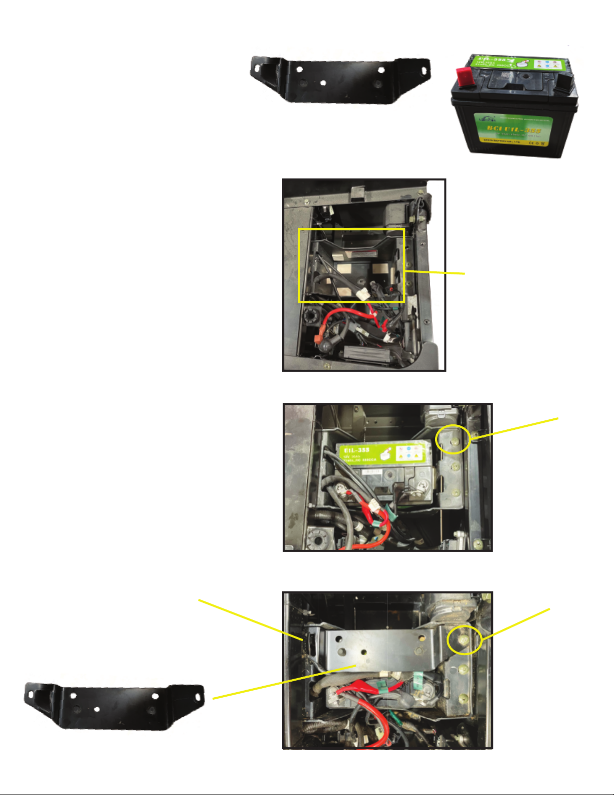
1. Remove bottom seat and located
battery box under driver side seat area.
2. Place battery inside battery box
ensuring not to damage or pinch battery
wires and remove battery terminal protective
caps.
3. Attach RED battery wires to positive
(+) battery terminal using supplied M6X15
BOLT, M6 washer and M6 Flange Nut.
WARNING! ALWAYS ATTACH POSITIVE
(RED) WIRES BEFORE NEGATIVE
(BLACK) WIRES TO BATTERY TERMI-
NALS.
4. Attach BLACK battery wires to
negative (-) battery terminal using supplied
M6X15 BOLT, M6 washer and M6 Flange
Nut.
5. Install battery bracket with angled
edge facing forward by removing the Phillips
head screw (show in picture below), place
battery over the battery, replace Phillips
head screw.
6. Re-install seat.
Tools Needed:
10mm Wrench
Phillips Head Screw Driver Battery Bracket
Battery
Battery Box
Remove screw
Press bracket
down and
replace screw
Place under seat
frame
8
9

SAFETY NET INSTALL
1. Locate safety net assemblies.
NOTE: they may be located inside of
glove box.
2. Install both latch straps to front
and rear points on roll cage.
Ensure the long strap faces the rear.
3. Remove rear floorboard Philips
screw.
4. Place safety net floor bracket on
floorboard mounting location and secure
with Phillips screw that removed earlier.
5. Pull each safety net strap until net
is secure in place.
Tools Needed:
Phillips Head Screw Driver
Strap Buckle
Long Strap
Mounting Locations
10
Table of contents