RectorSeal SAFE-T-SWITCH SS3 Operational manual

Description
Safe-T-Switch® Model SS3 specially designed mounting bracket mounts firmly over the edge of most drain
pans. The patented magnetic reed switch and slim profile can be installed on primary or auxiliary drain
pans. The SS3 switch is easily removed for cleaning and servicing.
US Patent No. 6,698,215
ComponentList:(See page 3)
(1) Bracket
(2) Stem assembly (includes Float, Tag, and Stem with wire)
(3) Thumb Screw (with 5/16 UNF thread)
(4) Warning Sticker (not shown)
Code Size Qty. per Case Lbs. per Case Cubic Ft per Case
97089 Safe-T-Switch SS3 24 50.73
Packaging
Maintenance
Inspect, clean and test this device at least every 30 days and following every cleaning of the drain line. 1. Clear debris or any other obstacles around the
Stem Subassembly. 2. Check for any damage. If damage is observed, replace this product with a new one. 3. Test switch function by following Step 6-7 in the
“AUXILIARY DRAIN PAN INSTALLATION” section below. If this product failed function test, replace it with a new one.
Wiring
1. Disconnect power to A/C unit at the main panel prior to performing electrical work.
2. If not present, it is recommended that an inline fuse be installed to protect 24-volt circuit and
time delay be congured to avoid rapid cycling of equipment. 3. Locate the 24-volt thermostat
cable entering the air handler unit. 4. Disconnect or cut the red wire and connect to switch lead
using wire nut. Connect other switch lead to air handler terminal. Incorporating switch in red circuit
shuts down entire unit. If placed in the yellow circuit, fan continues to run (to inhibit mold growth
during long absences.) 5. Reconnect power to the A/C unit. (Fig. 4)
To Switch
Red
White
Green
Yellow
From Thermostat
Wire Nut
Specications
24-Volts A/C, Maximum 1.25 Amp. Carrying Capacity, 6ft., 18 AWG Lead Wires.
PRODUCT DATA SHEET
Page 1 of 3
SAFE-T-SWITCH®SS3
For primary and auxiliary drain pans

Page 2 of 3
Installation Instructions:
Notice:Failure to read and comply with all warnings, cautions and instructions prior to starting installation may cause personal injury and/
or property damage and void the warranty.
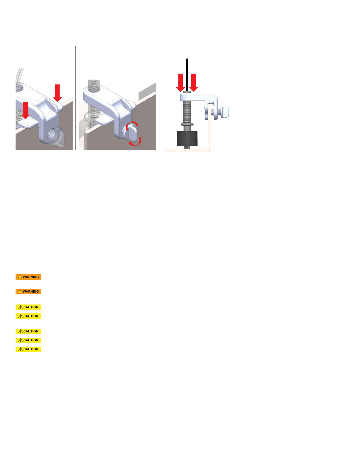
AUXILIARY DRAINPANINSTALLATION (Works with 1-2” deep drain pans):
1.Disconnect power to air conditioner (A/C) unit at main panel. 2. Clip Bracket onto the side of the auxiliary drain pan at the
lowest end (Fig 1). 3. Secure the Thumb Screw until the Bracket is rmly attached to the pan (Fig 2), ensuring switch wires are
positioned up. Float should move freely. 4. It is recommended to push the Stem to the bottom position for the most sensitive
water detection (Fig 3). Ensure Stem Subassembly is rmly secured to the bracket. 5. Wire the switch per instructions under
WIRING (Fig. 4). 6. Test the switch by lifting the Float while the unit is running. If wired correctly, the A/C unit will stop. 7. Test
switch sensitivity: Fill pan with water. Float should rise and A/C unit should stop before pan overows. If sensitivity needs to
be adjusted, move the Stem Subassembly up or down accordingly. 8. Place the included Warning Sticker on a visible surface,
such as the air handler or condenser unit.
Push stem to bo
om
(Fig.1) (Fig.2) (Fig.3)
IMPORTANT SAFETY INFORMATION:
1. This device must be installed strictly in accordance with manufacturer’s instructions (to ensure proper operation) and in accordance with all
applicable local plumbing, drainage and electrical codes.
2. Electric shock hazard. Disconnect power supply before installing this product to avoid electrical shock and/ or equipment damage.
Use in Class 2 (thermostat) circuit only, not to exceed 24-volts, 1.25 amps to avoid damage or re hazard.
1. This device will not detect clogs occurring upstream from the installation point.
2. If not present, it is recommended that a fuse and time delay be installed, to protect the 24-volt circuit and avoid rapid cycling of equipment,
prior to installing this product.
3. This product is intended for use in water only. Not for use in the presence of ammable liquids or vapors.
4. Refer to the appropriate HVAC equipment operation manual prior to installing this product.
5. Do not use on dual compressor systems.
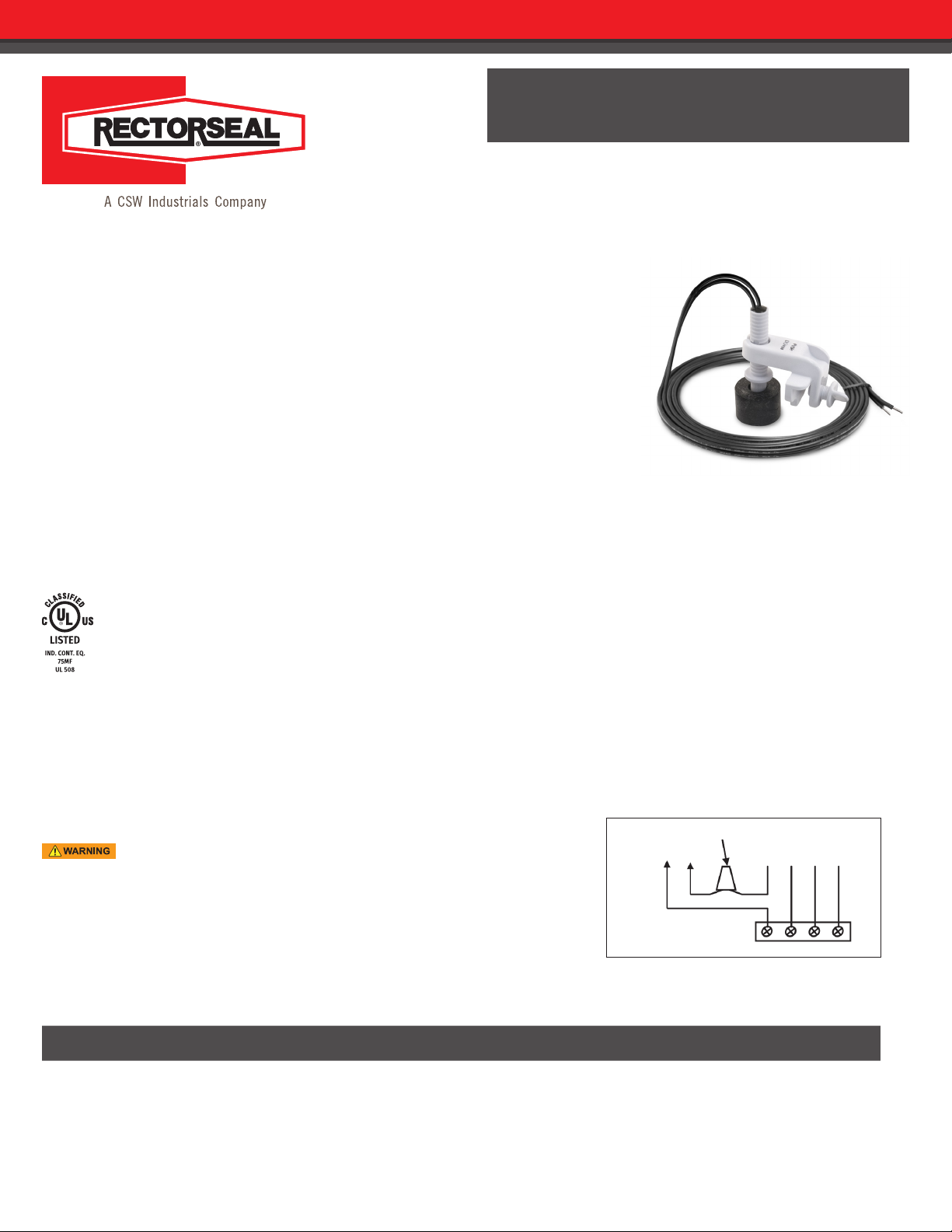
SAFE-T-SWITCH®SS3
For primary and auxiliary drain pans

Page 3 of 3
Limited Warranty
RectorSeal, LLC makes the Limited Express Warranty that when the instructions for storage and handling of our products are followed we warrant our products to be free from defects. THIS LIMITED EXPRESS
WARRANTY IS EXPRESSLY IN LIEU OF ANY OTHER EXPRESS OR IMPLIED WARRANTIES, INCLUDING ANY IMPLIED WARRANTY OF MERCHANTABILITY OR FITNESS FOR A PARTICULAR PURPOSE, AND OF ANY OTHER
OBLIGATION ON THE PART OF RectorSeal, LLC. The sole remedy for breach of the Limited Express Warranty shall be the refund of the purchase price. All other liability is negated and disclaimed, and RectorSeal,
LLC shall not be liable for incidental or consequential damages.
Manufactured by
RectorSeal, LLC
2601 Spenwick Drive Houston, TX 77055, USA 800-231-3345 Fax 800-441-0051 rectorseal.com
A CSW Industrials Company. RectorSeal, the logos and other trademarks are property of RectorSeal, LLC, its afliates or its licensor’s and are protected by copyright, trademark and other intellectual property laws,
and may not be used without permission. RectorSeal reserves the right to change specications without prior notice. ©2020 RectorSeal. All rights reserved. R50109-0620
The information contained in this drawing is the sole property of RectorSeal. Any reproduction in part or as a whole without the written permission of RectorSeal is prohibited.
Item No. Part Number Description Quantity
1ASB00452 Stem Assembly 1
2FAB01292 SS3 Tag 1
3FAB01293 Thumbscrew 1
4FAB01294 SS3 Body 1
Safe-T-Switch SS3 Assembly
SIZE DRAWING REV SCALE WEIGHT
ANumber Date 01-001-A 1:2 ––
ASB00454 5/8/2020
3
4
12
ITEM NO.
PART NUMBER
DESCRIPTION
QTY.
1
ASB00452
Stem Assembly
1
2
FAB01292
SS3 Tag
1
3
FAB01293
Thumbscrew
1
4
FAB01294
SS3 Body
1
DO NOT SCALE DRAWING
SHEET 1 OF 1
UNLESS OTHERWISE SPECIFIED:
SCALE: 1:2
WEIGHT:
REV
DWG. NO.
A
SIZE
TITLE:
NAME
DATE
COMMENTS:
Q.A.
MFG APPR.
ENG APPR.
CHECKED
DRAWN
FINISH
MATERIAL
INTERPRET GEOMETRIC
TOL. PER: ANSI Y14.5M-1994
APPLICATION
USED ON
NEXT ASSY
PROPRIETARY AND CONFIDENTIAL
THE INFORMATION CONTAINED IN THIS
DRAWING IS THE SOLE PROPERTY OF
RECTORSEAL. ANY REPRODUCTION IN
PART OR AS A WHOLE WITHOUT THE
WRITTEN PERMISSION OF RECTORSEAL IS
PROHIBITED.
5
4
3
2
1
ASB00454
THIRD ANGLE PROJECTION
01-001-A
5/8/2020
Jun Luo
DIMENSIONS ARE IN INCHES
TOLERANCES:
FRACTIONAL
1/16
ANGULAR:
1
X.X
.1
X.XX
.01
X.XXX
.005
X.XXXX
.0005
Safe-T-Switch
SS3 Assembly
3
4
12
ITEM NO.
PART NUMBER
DESCRIPTION
QTY.
1
ASB00452
Stem Assembly
1
2
FAB01292
SS3 Tag
1
3
FAB01293
Thumbscrew
1
4
FAB01294
SS3 Body
1
DO NOT SCALE DRAWING
SHEET 1 OF 1
UNLESS OTHERWISE SPECIFIED:
SCALE: 1:2
WEIGHT:
REV
DWG. NO.
A
SIZE
TITLE:
NAME
DATE
COMMENTS:
Q.A.
MFG APPR.
ENG APPR.
CHECKED
DRAWN
FINISH
MATERIAL
INTERPRET GEOMETRIC
TOL. PER: ANSI Y14.5M-1994
APPLICATION
USED ON
NEXT ASSY
PROPRIETARY AND CONFIDENTIAL
THE INFORMATION CONTAINED IN THIS
DRAWING IS THE SOLE PROPERTY OF
RECTORSEAL. ANY REPRODUCTION IN
PART OR AS A WHOLE WITHOUT THE
WRITTEN PERMISSION OF RECTORSEAL IS
PROHIBITED.
5
4
3
2
1
ASB00454
THIRD ANGLE PROJECTION
01-001-A
5/8/2020
Jun Luo
DIMENSIONS ARE IN INCHES
TOLERANCES:
FRACTIONAL
1/16
ANGULAR:
1
X.X
.1
X.XX
.01
X.XXX
.005
X.XXXX
.0005
Safe-T-Switch
SS3 Assembly
SAFE-T-SWITCH®SS3
For primary and auxiliary drain pans