RED-RING Professional SB Manual

12
(A3 Leaflet No.571-2287-01c)
Applied EnergyProducts Limited,
MorleyWay, Peterborough, PE2 9JJ, UK
Telephone: +44 (0) 844 372 7761 / Fax: +44 (0) 84 372 7762
Website: www.applied-energy.com
TechnicalAdvisoryService Hotline: +44 (0) 844 372 7766
THE
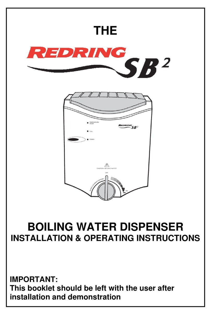
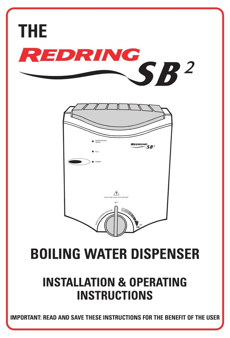
BOILING WATER DISPENSER
INSTALLATION & OPERATING INSTRUCTIONS
IMPORTANT:
This booklet should be left with the user after
installation and demonstration

2
Contents
Installation Instructions Page
Important notes - installation . . . . . . . . . . . . . . . . . . . . . . . . . . . . . . . . . . . . . . . . . . . . . . . 3
What the installer will need. . . . . . . . . . . . . . . . . . . . . . . . . . . . . . . . . . . . . . . . . . . . . . . . 3
Where to locate the unit . . . . . . . . . . . . . . . . . . . . . . . . . . . . . . . . . . . . . . . . . . . . . . . . . . 4
Installing thewater supplyand steam vent pipes . . . . . . . . . . . . . . . . . . . . . . . . . . . . . . . 4
Installing themains supply . . . . . . . . . . . . . . . . . . . . . . . . . . . . . . . . . . . . . . . . . . . . . . . . 4
Removing the front cover . . . . . . . . . . . . . . . . . . . . . . . . . . . . . . . . . . . . . . . . . . . . . . . . . 4
Model range and unit performance details . . . . . . . . .. . . . . . . . . . . . . . . . . . . . . . . . . . . 5
Unit schematic . . . . . . . . . . . . . . . . . . . . . . . . . . . . . . . . . . . . . . . . .. . . . . . . . . . . . . . . 6
Fixing the unit on the wall . . . . . . . . . . . . . . . . . . . . . . . . . . . . . . . . .. . . . . . . . . . . . . . . . 7
Connecting the water supplyand steam vent pipes . . . . . . . . . . . . .. . . . . . . . . . . . . . . . 7
Connecting the mains cable . . . . . . . . . . . . . . . . . . . . . . . . . . . . . . .. . . . . . . . . . .. . . . . 7
Replacing the front cover . . . . . . . . . . . . . . . . . . . . . . . . . . . . . . . . . . . . . . . . . . . . . . .. . 7
Operating Instructions
General product description . . . . . . . . . . . . . . . . . . . . . . . . . . . . . . . . . . . . . . . . . . . . . . . 2
Howto operate the unit . . . . . . . . . . . . . . . . . . . . . . . . . . . . . . . . . . . . . . . . . . . . . . . . . . 8
Howto maintain and descale your unit . . . . . . . . . . . . . . . . . . . . . . . . . . . . . . . . . . . . . . . 9
Trouble shooting guidance. . . . . . . . . . . . . . . . . . . . . . . . . . . . . . . . . . . . . . . . . . . . . . . . 10
After Sales Service . . . . . . . . . . . . . . . . . . . . . . . . . . . . . . . . . . . . . . . . . . . . . . . . . . . . . . 11
Important notes – PAT testing . . . . . . . . . . . . . . . . . . . . . . . . . . . . . . . . . . . . . . . . . . . . . 11
Guarantee . . . . . . . . . . . . . . . . . . . . . . . . . . . . . . . . . . . . . . . . . . . . . . . . . . . . . . . . . . . . . 12
Thank you for choosing a quality Redring product from Applied
Energy Products Limited, Peterborough, U.K
General Product Description
The “SB Professional Range” are wall mounted, self-calibrating and self-filling boiling wa
ter heaters.
Theycan be used for making cups of tea orcoffee and even soupsand hot snacks.
A special condenser traps steam and returns droplets to the tank, minimising waste and saving
energy.
The water temperature is set at approximately95°C (dependent on unit volume) and automatically
maintained bythe unit.
Pulling the front lever forward dispenses hot water.
11
ImportantNotes
The heater level detection system uses two protective resistors to earth, this results in an insulation
resistance (IR) of 0.5M Ω, and asa consequence the equipment would appear to faila routine
Portable Appliance Test (PAT).
This is onlyrelevant if the unit is fitted with a standard 13A plug, however, this product is not to be
classed as a portable appliance, and as detailed on page 3, it is instructed that the unit is to be wired
to a means for disconnecting the fixed wiring in all poles in accordance with the wiring rules
(eg. 13A fused double pole isolating switch).
In the unlikelyevent that the unit is fitted incorrectly, the recommendation is if test iscarried out with
water in the tankthe IR reading will be 0.5MΩ. Ifthis becomes an issue to the PAT engineer, switch
off the power and drain the tankthrough the tap prior to connection test.
PATtest is not acase ofpass/fail. IfPATrecords negative then thisis not a failure. It highlights the
possibility ofa failure and then the unit should undergo further investigation.
With regards to BS EN60335-1 Clause 16 earth leakage (not IR) can be 0.7A per kW= 1.8mA.
Test at 254V (6%above nominal) / 1.8Ma =141k Ω so reading of0.5MΩ is acceptable.
After SalesService
We offer a technical advisoryservice on thetelephone to contractors and other customers with
problems in the field. RING 0844 372 7766
Spare parts can be supplied against Credit or Debit cards.
RING 08443727750
Remember to quote the exact model ofunit, as written on the front ofthe unit and on this leaflet.
It mayalso be ofuse to have a note of the model and serial numberasstated on the underside of the
unit.
This appliance is not intended for use by persons (including children and the infirm) with
reduced physical,
sensory or mental capabilities,or lack of experience andknowledge,
unless they have been given supervision or instruction concerning use of the appliance
by a person responsible for their safety.
Childrenshould be supervised to ensure that they do not play with the appliance.

10
Trouble Shooting – Service Hints
If the unit is not working satisfactorily
, make the followingchecks before calling out the contractor.
Anyone ofthese adjustmentscould restore the performance.
WARNING: SWITCH OFF THE ELECTRICITYAT THE ISOLATING SWITCH
BEFORE REMOVING THE COVER TO MAKE CHECKS
SYMPTOM POSSIBLE CAUSE ACTION
No water from tap
Water solenoid valve closed.
Blockage in system.
Control board fault.
Water supplyfailed.
Check coil for open circuit.
Check pipes.
Call Technical Service Helpline.
Check other water outlets in building.
Unit fails to heat water
Tripped thermal overload.
Control board fault.
Steam sensor fault.
Heating element fault.
Reset – Call Technical Service Helpline.
Call Technical Service Helpline.
Replace element
Excess steam or
Overflowfrom vent
Inlet valve jammed open.
Control board fault.
Heating element fault.
Clean or replace.
Replace.
Replace.
Water flows from
steam vent outlet Faultyearth connection. Check earth connection for continuity.
Call Technical Service Helpline or a
qualified electrician.
Steam and veryhot
water dribbles out the
vent on the underside
of unit
Pipe not fitted to steam vent. Contact installer ifmissing.
Call Technical Service Helpline.
Solid particles are
visible in the water Scale has built up inside the
tank. Carryout descaling procedure.
3
Installation Instructions
Important Notes
•
All installations must be undertaken bya competent installer.
If in anydoubt, advice and assistanceshould be sought from a qualified plumber
and/or electrician.
•
Installation and wiring must conformto the current BS.7671 (IEE Wiring Regulations)
and the Water Fittings Regulations. Local regulations mayapplyin other countries.
•The steamvent connection MUST BE MADE, as requiredin these instructions.
•Ameans fordisconnection in all poles must be incorporated inthe fixed wiring in
accordance with the wiring rules.
•Check that the mains supplymatches the electrical rating on the product.
The rating plate is located on the bottom edge of the unit.
•THIS APPLIANCE, AND ALL METAL PIPEWORK CONNECTED TO IT, MUSTBE EARTHED.
•This appliance must be connectedtoa TN-Systemel
ectrical power supply.
This has a common earth-point. It is not suitable for an IT-System electrical powersupply
as this has an isolated earth-point.
Please note: this is applicable for some Europeaninstallations.
•Frost Protection: This appliance should be located where the ambient air temperature is
between 5°C and 50°C.
If the temperature mayfall below5°Cwhenthe appliance is not in use, do not turn off the
appliance electrically.
This safeguard does NOT offer protection to the connecting pipe work andfittings.
The unit should not be operated if freezingis suspected.
Allowthe unit to thawcompletely.
•This unit must not be cleaned by, or installed in anarea cleaned by, a waterjet.
•If you have anyqueries about installing this product or after it has been installed, please
contact the Applied Energy CustomerService Helpline on 0844 372 7766.
Customers outside the U.K. should contact their local Redringdistributor.
What the installer will need
•A meansfor disconnecti
ngthe fixed wiring in all poles in accordance with the wiring rules
(eg. 13A fused double pole isolating switch).
•Suitable length of1.0mm² 3-Core multi-strand PVC insulated mains cable that complies with
BS.6500.
•Suitable lengthsofØ15mm copper pipe.

4
Where to locatethe unit
•We recommend that the unit is installed on a suitablewall, at shoulder height and over a sink.
•Adjacent to the means for disconnecting the fixed wiring in all poles in accordance with the wiring
rules (ie: 13A fused double pole isolating switch).
•Available mains cold water supplyand drainage facility.
•DO NOTinstall the unit within reach of a person using a bath or shower.
•This unit must not be installed in an area cleaned bya water jet.
•DO NOTobstruct the ventilation channels on the top ofthe cover plate.
Installing the water supplyand steam vent pipes
The unit must be connected to cold, mains fed, drinking water only.
Pressure range between 0.2 MPa (2.0 bar / 29psi) and 1.0 MPa (10.0 bar / 140 psi).
DO NOT connect to a storage tank
•Isolate the water supply
•Layin the Ø15mm water supplypipe to the location ofthe inlet connection.
•Layin the Ø15mm drainage pipe to the location of the steam vent connection.
•
The steam vent connection must be taken directlyto the sink below, ifthere is one,
or via a tun
dish to a suitable drain.
If a sinkis used it must be able to withstand boiling water and have an overflowconnection.
Installing themains supply
If a mainssupply is not alreadyavailable.
•Install a meansfor disconnecting the fixed wiring in all poles
(eg. 13A fused double pole isolating switch) adjacent to where theunit will be fixed.
Removing the front cover
•Ensure unit is disconnected from mainselectricitysupply.
•Ensure unit is emptied ofwater through opening oftap and allowunit to cool.
•Unscrewthe front tap.
•Remove the screws from the bottom and top edge of the unit.
•Disconnect the neon light, carefullyunclipping it from the front cover.
9
Maintenance/ DescalingProcess
ToDrain the unit
•Turn off the water and electricitypowersupplies.
•Turn on the tap on the front of the unit to drain the tank.
•Unscrewand remove the tap and remove 4 fixing screws on outercover.
•Shield the electronic controller from possible water damage.
•Carefullyremove the drain plug from the bottom ofthe tank and drain.
WARNING: Beware of splashing water as it maybe near boilingpoint.
Descaling
If scale comes out with the hot water then the unit mayneed to be descaled.
As with all waterheaters scale will buildinside the tank.
Howquicklythis build up occurs will depend on the hardness of the water andthe frequency
ofuse.
Please followthe procedure below:-
•Asuitablyqualified person should carryout the descaling.
•Ensure the mains electricitysupplyis isolated.
•Unscrewand remove tap.
•Remove 4 fixing screws on outer cover.
•Remove draining plug on bottom ofwater tank.
•After water hasdrained out replace plug.
•Mix2 teaspoons (approximately10ml) food grade citric acid into a cup of water.
•Feed citric acid through tap hole (eitherbyfunnel or placing tap half wayon the thread, turning
upside down with the tap lever permanentlyopen).
•Tighten tap, leaving outside cover off.
•Turn power on, unit will cycle and fill. Allowunit to boil for 10 minutes then drain.
•Turn power off.
•Drain unit and remove tap.
•Replace outside cover.
•Replace tap, turn power on.
•Wait until unit has filled with water – drain once again from tap, allowunit to refill.
•Unit is readyfor use.
Cleaning:
•Before cleaning, switch off the electricityat the isolating switch.
•It is recommended that the unit surfacesare cleaned with a soft cloth.
•Do not use abrasive or solvent cleaning fluids.

8
Operating Instructions
Initial Operating Instructions
•Make sure the water is turned on prior to mains electricitysupply.
•Check all connections forwater leaks.
•Turn on the power and wait approximately20 minutes before using.
Priming theunit
When the power is turned on for the first time the unit will automaticallyprime itself, covering the
heating element.
The heating element will then switch ON and boil that amount ofwater(this will take 10-15 minutes)
starting the automatic Heat and Refill process until the tank is full.
The unit then goes into maintenance mode, keeping the water at the required temperature.
Th
e unit should be switched offat the mains if the water is not required for a long period oftime
(eg: at weekends, holidays etc).
Pleasenote
•The unit can take severalminutes to reach the required temperature, dependingon usage and
tank capacity.
•When first installed, it is recommended that the initial tank of boiling water is fully drawn off and
discarded. Allowthe tankto re-fill before using the unit.
POWER light
When the unit ison, the POWER light will be illuminated.
SafetyFeatures
•The boiling water unit is fitted with a MANUAL RESETSAFETY DEVICE, which operatesin a
BOIL DRY situation, and a MANUAL RESET THERMOSTAT, for detecting excessive steam in
the event of electronic controller failure or water solenoid valve failure.
•
Unless you are a qualified engineer DO NOTATTEMPT to repair this unit yourself.
In the eventofmalfunction please contact ourTechnical Service Helpline on 0844 372 7766.
WARNING
•SCALDING HOT WATERwill be dispensed from the unit.
•Never washyour hands directlyfromthe unit.
•Some plastic cups can distort if theyare filled with boiling water, so causing a dangerof
scalding.
•Do not use if heateris suspected of beingfrozen.Allowto thaw completelybefore use.
5
Model Rangeand Unit Performance Details
MODEL 2.5l 5l 7.5l 10l 15l 20l 25l
Storage Capacity(litres) 2.5 5 7.5 10 15 20 25
Initial DrawOff(170ml) 15 30 45 60 100 120 150
Initial DrawOff(litres) 2.5 5 7.5 10 15 20 25
First Hour Delivery(cups) 125 135 150 175 200 225 250
RecoveryRate
(cups per hour) 125 125 125 125 125 125 125
Electrical Heating
Element (kW) 2.4 2.4 2.4 2.4 2.4 2.4 2.4
Approximate Weight (kg) 6 7 8 9 10 12 13
Approximate Laden
Weight (kg) 8.5 12 15.5 19 25 32 38
A – Height (mm) 430 510 510 565 565 630 630
B – Width (mm) 315 370 370 425 425 490 490
C - Depth (mm) 210 250 250 320 320 350 350
D – Depth (mm) 125 170 170 240 240 270 270
E – Tap Height (mm) 185 185 185 185 185 185 185

6
Schematic Diagram
7
Fixing theunit to the wall
•Suitable screws and washers must be used through the designated keyholes on the backplate of
the unit ensuring the unit securelyfastened to the wall.
•Ensure the fixing screws are horizontaland the unit, when installed, is level.
Connecting the water supplyand vent pipes
•When the unit is fixed to the wall, makethe final water supplyand steam vent connections and
secure the pipework.
•Switch the water supplyback on.
Connecting the mains cable
•Ensure the mains supplyis isolated.
•Connect the mains cable from the unit to the means for disconnection (eg. 13A fused double pole
isolating switch).
•Ensure the cable clamps are firmlysecured and the cable endsare tightened into the terminal
block.
No
te:
The supplycable must be a minimum of1.0mm² 3-Core multi-strand PVC insulated mains
cable
. The terminal block will not acceptcable diameters above 1.5mm².
Check that the mains supplymatches the electrical rating on the product.
The rating plate is located on the bottomedge of the unit.
IMPORTANT:
Connect the supplycable, complying with BS.6500, to this appliance inaccordance with the
following code:
GREEN AND YELLOW (EARTH) connectto the terminal marked “ ” .
BLUE (NEUTRAL) connect to terminal marked “N”.
BROWN (LIVE)connect to terminal marked “L”.
WARNING: THIS APPLIANCE, ANDALL MET
AL PIPEWORK CONNECTED TO IT,
MUST BE EARTHED.
Replacing the front cover
•Support the front cover and re-attach the neon light carefullyclipping to the unit.
•Replace the front cover and secure using the top andbottom screws.
•ApplyTeflon tape to tap thread and screw-in.
•Reconnect the mains water supply.
•Check for anyleaks and make good prior to turning mainselectricitysupplyon.
Table of contents
Other RED-RING Water Dispenser manuals
Popular Water Dispenser manuals by other brands

Alhafidh
Alhafidh DHA-49AUW user manual

Proficient H2O
Proficient H2O Pro315 Next Gen TA HE Alternating manual

Hydroflow
Hydroflow k40 instructions

Watts
Watts Pure Water PWS10 Series Installation, operation and maintenance

Lincoln Electric
Lincoln Electric COOL ARC IM670-A Operator's manual

BWT
BWT Perla Silk S Installation and operating manual