RED-RING SB2 Manual

12
Full details and terms and conditions of guarantee areavailableon request from: -
APPLIED ENERGYPRODUCTS LIMITED
MORLEYWAY, PETERBOROUGH PE2 9JJ
TEL +44 (0) 844372 7761 / FAX: +44(0) 844 3727762
Website: www.applied-
energy.com
(A4 Leaflet No.571-2278-01e)
THE
BOILING WATER DISPENSER
INSTALLATION & OPERATING INSTRUCTIONS
IMPORTANT:
This booklet should be left with the user after
installation and demonstration

2
Contents
Installation Instructions Page
Important notes. . . . . . . . . . . . . . . . . . . . . . . . . . . . . . . . . . . . . . . . . . . . . . . . . . . . . . . . . 2
What the installer willneed. . . . . . . . . . . . . . . . . . . . . . . . . . . . . . . . . . . . . . . . . . . . . . . . 3
Where to locatetheSB² . . . . . . . . . . . . . . . . . . . . . . . . . . . . . . . . . . . . . . . . . . . . . . . . . . 3
Installing thewater supply andsteamvent pipes . . . . . . . . . . . . . . . . . . . . . . . . . . . . . . . 3
Installing themainssupply . . . . . . . . . . . . . . . . . . . . . . . . . . . . . . . . . . . . . . . . . . . . . . . . 4
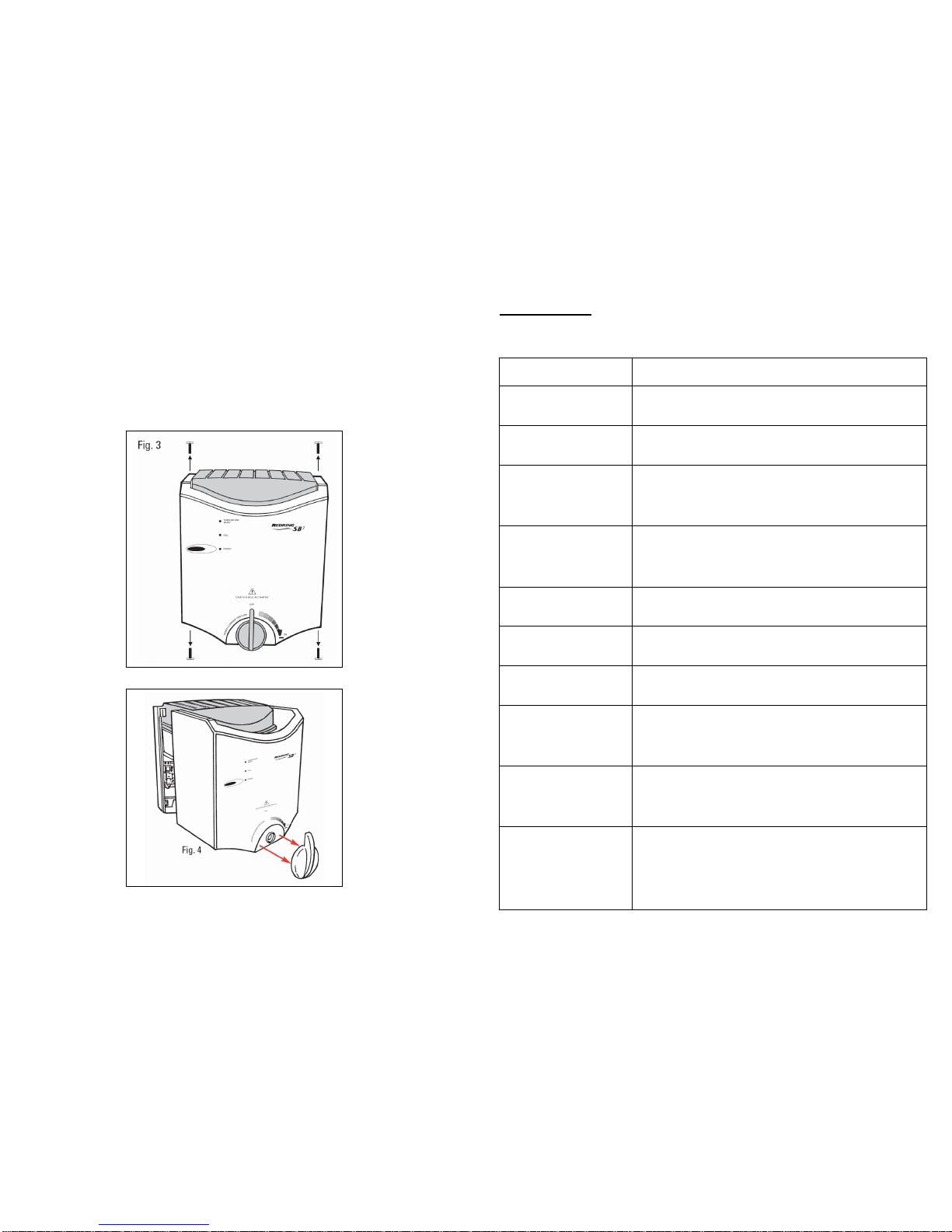
Removingthe front cover . . . . . . . . . . . . . . . . . . . . . . . . . . . . . . . . . . . . . . . . . . . . . . . . . 4
Fixingthe unit onthewall . . . . . . . . . . . . . . . . . . . . . . . . . . . . . . . . . . . . . . . . . . . . . . . . . 6
Connecting the water supplyandsteamvent pipes. . . . . . . . . . . . . . . . . . . . . . . . . . . . . 6
Connecting the mainscable . . . . . . . . . . . . . . . . . . . . . . . . . . . . . . . . . . . . . . . . . . . . . . . 6
Replacing the front cover . . . . . . . . . . . . . . . . . . . . . . . . . . . . . . . . . . . . . . . . . . . . . . . . . 6
Schematicwiring diagram . . . . . . . . . . . . . . . . . . . . . . . . . . . . . . . . . . . . . . . . . . . . . . . . 6
Operating Instructions
General product description . . . . . . . . . . . . . . . . . . . . . . . . . . . . . . . . . . . . . . . . . . . . . . . 7
How tooperate the SB² . . . . . . . . . . . . . . . . . . . . . . . . . . . . . . . . . . . . . . . . . . . . . . . . . . 7
How toclean and descale your SB² . . . . . . . . . . . . . . . . . . . . . . . . . . . . . . . . . . . . . . . . . 8
Trouble shootingguidance . . . . . . . . . . . . . . . . . . . . . . . . . . . . . . . . . . . . . . . . . . . . . . . . 9
After SalesService . . . . . . . . . . . . . . . . . . . . . . . . . . . . . . . . . . . . . . . . . . . . . . . . . . . . . . 11
Guarantee . . . . . . . . . . . . . . . . . . . . . . . . . . . . . . . . . . . . . . . . . . . . . . . . . . . . . . . . . . . . 12
Thankyou for choosing aquality Redring product manufactured in Peterborough, England
Installation Instructions
Important Notes
•This appliance is intended to be used in household and similar applicationssuchas: -
-staff kitchenareas in shops, offices and other working environments;
- farm houses;
- byclients in hotels, motels and other residential type environments;
-bed and breakfast typeenvironments.
•All installations mustbe undertaken bya competent installer.
If in anydoubt, advice and assistance should besought from aqualified plumber
and/or electrician.
•Installation and wiring must conf
orm to the current BS.7671 (IEE Wiring Regulations)
and the Water Fitting Regulations. Local regulations mayapply in other countries.
•The steam vent connection MUST BE MADE, as required in these instructions.
•A means fordisconnection in all poles must be incorporated in thefixed wiring in
accordance with the wiring rules.
•
Check that the mainssupplymatches the electrical rating on theproduct.
The rating plate is located on thebottom edgeof the unit.
•Frost Protection: This appliance should be located wherethe ambient air temperatureis
between 5°C and 50°C. If the temperaturemayfall below 5°C when the appliance is not in
use, do not turn off the applianceelectrically. This safeguard does NOT offer protection to
the connecting pipe work and fittings. The unit should not be operated if freezing is
suspected. Allow the unit to thaw completely.
•This unit must not be cleaned by, or installed in an areacleanedby, awater jet.
•THIS APPLIANCE,AND ALL METAL PIPEWORK CONNECTED TO IT, MUSTBE EARTHED.
•If you have anyqueriesabout installing thisproduct or after it has been installed, please
contact ourCustomerService Helpline on 0844372 7766
.
Customersoutsidethe U.K. should contact their local distributor.
•This product mayneed to be descaled regularly.
The frequencyof descaling will depend on the hardness of the watersupply.
11
Redring After Sales Service
Weoffer a technical advisory serviceon the telephone to contractors andother customers with
problems in the field.
RING0844 372 7766
Some partscan be supplied against Credit or Debit cards.
RING0844 372 7750
Remember to quote theexact model of SB² unit, aswritten on the front of the unit and on thisleaflet.
It may also be of use tohavea note of the model and serial number asstated on theunderside of the
unit.
Spare Parts
Part Number Part Description
95-719601
95-719613
95-719614
95-719615
95-719616
95-719617
95-719618
95-719608
95-719609
95-719619
95-719611
95-719620
Element assembly
Terminal block
Logic boardassembly
Power PCB assembly
Solenoid valve
Float switch
Cable pack
Control knob
Outlet spout
Scaletrap
Outlet valve
Inlet elbow assembly (includesflow regulator)
Thisappliance isnot intended for use by persons (including children and theinfirm) with
r
educed physical, sensoryor mental capabilities, or lack of experience and knowledge,
unless they have been given supervision or instruction concerning use of theappliance
by a person responsible for their safety.
Children should be supervised to ensure that they do not play with the appliance.

10
PROFESSIONAL SERVICE:
If the SELF HELP checksdo not cover the symptom, youshouldseekprofessional help.
The followingadditional checklist isprovided for the benefit of the qualified service person.
WARNING: SWITCH OFF THE ELECTRICITYAT THE ISOLATING SWITCH
BEFORE REMOVING THE COVER TO MAKE CHECKS
a) Unit failsto heat the water Check that thewater supply is on and that itspressure isbetween
0.069 MPa (0.7 bar / 10 psi) and 1.0 MPa (10.0 bar / 140 psi).
Check circuit through solenoidcoil.
Check circuit through theheatingelement.
Check circuit through float switch
If defective thenreplace.
b) All thelight are outand
the POWER buttondoes
not work
Ensure that the electricitysupply isswitched on at the local isolator.
Ensure that the flyinglead to the front cover isconnected properly
(see Fig.5aand 5b).
Check the supply to the PCB. If supplyOKthenchangePCB.
c) Water flowscontinually
from the steam vent pipe Check that thefloat switch operatescorrectly and switchesthe
water solenoidonand off.
d) The water tanktakes
more than20minutesto
fill withwater
Check that thewater supply is on and that itspressure isbetween
0.069 MPa (0.7 bar / 10 psi) and 1.0 MPa (10.0 bar / 140 psi).
Check operation of thewater solenoid and that water flows into the
tankat aratebetween 0.3 litres/minuteand 1.0 litres/minute.
Check circuit through thesolenoid coil
If defective thenreplace.
SB² Heat up times (table 3):
CONDITION APPROXIMATE
HEATUP TIME
2.5 Litre SB²
APPROXIMATE
HEATUPTIME
4Litre SB²
WHAT ELSEHAPPENS
SB² isswitched
onat the local
isolator andthe
unit isempty of
water.
POWER buttonis
pressed.
12minutes
(4 minutesfilling
8minutesheating)
18 minutes
(5minutesfilling
13 minutesheating)
-POWER light comeson
-then FULLlight comes on
-then TEMPERATURE READY
light comeson
-then steam comes out of vent
for 30 seconds
SB² isswitched
onat the local
isolator andthe
unit isalready full
of cold water.
POWER buttonis
pressed.
8 minutes 13 minutes -POWER and FULL lightsboth
come on
-then TEMPERATURE READY
light comeson
- thensteamcomesout of vent
for 30 seconds
3
Whatthe installer will need
•A meansfor disconnectingthefixed wi
ringin all polesin accordance withthewiring rules
(ie. 13A fused doublepoleisolating switch).
•Suitablelength of 1.0mm² 3-Coremulti-strand PVC insulated mainscablethat complieswith
BS.6500.
•Suitablelengthsof Ø15mm copper pipe.
Where tolocate the SB²
•Werecommend that the unit isinstalledon a suitable wall, at shoulder heightand over asink.
•Adjacent to themeansfor disconnecting the fixed wiring in all polesinaccordance with the wiring
rules(ie: 13A fused double pole isolating switch).
•Available mainscold water supply and drainage facility.
•DO NOT install theSB² withinreachof a person using abath or shower.
•Thisunit must not beinstalled in an area cleanedbya water jet.
•DO NOT obstruct the ventilation channel in the backplate.
Installingthewater supply and steam vent pipes
The unit must be connected to cold, mainsfed, drinking water only.
Pressure range between 0.069 MPa (0.7 bar / 10 psi) and1.0 MPa(10.0 bar / 140psi).
DO NOTconnect to a storage tank
•Isolate the water supply
•Layinthe Ø15mm water supply pipe tothe location of theinlet connection (
Fig.1).
Check that the water supply position givesenough spaceunder the unit for it tobe used properly.
Flush through the water supplybefore making thefinal connection so that anydebris isremoved.
•Note: The inlet elbow contains aflow regulator: THIS MUSTBE USED IN INSTALLATION
•
Layinthe Ø15mm drainagepipe to the locationof the steam vent connection (Fig.1).
Connection ismadeusing the push-fit adaptor provided.
•Thesteamvent connection must betaken directlyto the sinkbelow, if there is one, or via a
tundish to asuitable drain.
If a sink isused it must be able to withstand boiling water and have an overflow
connection.
•Note: The steam vent outlet also acts as an overflow.

4
Installingthe mains supply
If a mains supply isnot already available.
•
Installa meansfor disconnectingthe fixed wiring inall poles
(ie. 13A fused doublepoleisolating switch) adjacent towhere the unit will be fixed.
Removing thefront cover
•Removethe screw from the bottom and topedge of the unit (Fig.3).
•Support the front cover and remove the flow knob (Fig.4).
•Pull the front cover away formthe unit and carefully remove the flying-leadand plug from the
back-plate connector (Fig 5aand Fig.5b).
9
Trouble Shooting
SELF HELP: If the SB² is not working satisfactorily, make the following checks before callingout the
contractor. Any one of theseadjustmentscould restore the performance.
a) TEMPERATURE READY
light isnot on Thisisnormal: The water hasnot yet reachedthe set temperature.
(See Table3 on page 10 for approximate heat up times).
b) TEMPERATURE READY
light isonbut the FULL
light isoff
Thisisnormal: Some water hasbeen takenout of the tankso it is
no longer full, but the water temperature is still hot enough to use.
(The tankwill automatically fill upagain).
c) The FULL light ison but
the TEMPERATURE
READY light isoff
Thisisnormal: The tankwill have automaticallyfilled and the
heater is still getting the water upto theboil.
(See Table3 on page 10 for approximateheat up times).
d) The POWER light is on
but the
TEMPERATURE
READY and FULL
lightsare both off
Thisisnormal: The tankisstill filling up withwater and the heater is
stillgetting up tothe boil.
(See Table3 on page 10 for approximateheat up times).
e) TEMPERATURE READY
light isonbut the water is
not boiling
To avoidenergy wastage, the SB² isdesigned to automatically
reduce the temperature by10°C if the unit isnot usedfor more
than 60 minutes.
(The SB² will automatically go back to boiling when the water is
used).
f) All thelightsareout and
the POWER buttondoes
not work
Ensure that the electricitysupply isswitched on at the local isolator,
andthen press the POWER button.
g) The water flowing from the
outlet is sometimesonly a
trickle
The water in the tankhasbeen drained out due toa high demand.
Wait for the FULLandTEMPERATURE READY lights to comeon
again.
h) The SB² takesa long time
toreachtheselected
temperature
When the SB² is first switched on it can take up to18minutes to
reach the Boil setting.
(See Table3 on page 10 for approximateheat up times).
i) Steam and very hot water
sometimesdribble out of
the vent at the back of the
SB²
Check that a pipehasbeen fittedto thesteam ve
nt.
Contact your installer if missing.
Use the POWER button topower down the unit and not the mains
electrical local isolator.
(This will reducetheamount of steam produced).
j) Thewater tastes different The new SB² needsto be flushed out before being used first used.
Werecommendthat the initialtankof boiling water isfully drawn off
anddiscarded.
Wait for the FULLandTEMPERATURE READY lights to comeon,
before using theunit.
k) Solid particles are visible
in the water Scale has built up inside thetank.
As with all water heatersscale may build up inside the water tank.
How quickly this build up occurs willdepend on the hardness of the
water and the usageof theSB².
Descalethe SB² heater tank(Thisshouldbecarried out by a
suitably qualifiedperson).
Werecommendthe useof inline resin filtersto protect the heater.

8
Please Note:
•TheSB² can take several minutestoreachtherequired temperature, depending on usage and
tankcapacity.
•To avoid energywastage, the SB² will automatically reduce the temperature by 10°C if the unit is
not used for more than 60minutes.
TheSB² will automatically go back to boilingwhen the water isused.
•When the SB² isswitched on at the localisolator andthe POWER buttonispressed, it will start
by self-calibrating. This can takeup to 20 minutestocompleteandincludesautomatically boiling
the water for30 seconds.
•When first installed, it isrecommended that the initial tankof boiling water is fully drawn off and
discarded. Allow the tankto re-fill and the TEMPERATURE READY light to come on, before
usingtheSB²
Dispensing water from the SB²:
•Place your cup under the red spout at the bottom of theunit.
•Turntheknob clockwise to fill your cup(Fig.7b).
•Turntheknob anti-clockwise toOFF (Fig.7a).
WARNING
•SCALDING HOT WATER can bedispensedfrom the SB².
•Never wash your hands directlyfrom theunit.
•Some plastic cups can distort if theyarefilled with boiling water, so causing a danger of
scalding.
•Do not use if heater is suspected of being frozen. Allow to thaw completelybefore use.
Howto clean anddescale your SB²
Cleaning:
•Before cleaning or descaling, switch off the electricityat the isolating switch.
•It is recommendedthatthe SB² surfacesare cleaned with asoft cloth.
•Do not use abrasive orsolvent cleaning fluids.
Descaling:
•A suitablyqualified person should carryout the descaling.
•Ensure themains electricitysupplyisisolated.
•If scalecomesout withthehot water thentheSB² may need to be descaled.
Thisisdonebyremovingthe front cover and top condenser assemblyand using asuitablekettle
descaler (a packet has been supplied). Ensureunit isthoroughly flushed through after descaling.
5

6
Fixingthe unitto the wall
•Usethewall mounting bracket supplied andthetwo lower fixingholes.
Ensure that the wallmounting bracket ismounted horizontally.
•An extra top fixing point isavailable by temporarily removing the condenser assembly.
Connecting the watersupply andvent pipes
•When the unit isfixed to the wall, make the finalwater supply and steam vent connectionsand
secure the pipework.
•Switch the water supply back on.
Connecting the mains cable
•Ensurethemainssupplyisisolated.
•Connect the mainscable from the SB² tothemeansfor disconnection (ie. 13Afuseddouble pole
isolating switch).
•Ensurethecable clampsare firmlysecuredand the cable endsare tightened into the terminal
block.
Note:
The supply cable must be a minimum of 1.0mm² 3-Core multi-strand PVC insulated mains
cable. The terminal block will no
t accept cablediameters above 1.5mm².
Check that the mains supplymatchesthe electrical rating on the product.
The rating plate is located on the bottom edge of the unit.
IMPORTANT:
Connect the supply cable, complying with BS.6500, to this appliance in accord ancewith the
following code:
GREEN AND YELLOW(EARTH) connect to the terminal marked ““.
BLUE (NEUTRAL) connect to terminal marked “N”.
BROWN (LIVE) connect to terminal marked “L”.
WARNING: THIS APPLIANCE, AND ALL METAL PIPEWORK CONNECTED TO IT,
MUSTBE EARTHED.
Replacing the front cover
•Support the cover and re-attach the flying-leadto theunit.
•Replace the front cover and secure using the top andbottom screws.
•Carefully replacetheknob, ensuring correct alignment of the“D-Shaft”.
•Reconnect the mainssupply.
Schematic
Wiring
Diagram
7
Operating Instructions
General Product Description
The SB² isawall mounted, self-calibrating and self-fillingboiling water heater.
It can be used for making cupsof tea or coffee and even soupsandhot snacks.
A special condenser trapssteam and returnsdroplets to the tank, minimising wasteand saving
energy.
The water temperature isset and automaticallymaintainedby the SB² and the unit ispowered down
with the “Power” button. Water isdispensed by rotating the front cover knob clockwise.
Howto operate the SB² (see Fig.6)
•Make sure the electricity and water are turned on.
•
Usethe“POWER” button toswitch on the SB² onand topower down.
TheSB² should be switched off at the mainsif the water isnot requirede.g. at weekends,
holidays etc.
POWER light: whenthe SB² is on thePOWER light will come on.
FULL light: Full light comeson whenthe tankisfull of water.
The SB² fillsup automatically and thiscan take up to 10 minutesif the tankis
completely empty.
TEMPERATURE TEMPERATUREREADY light comes on when the water ishot enough to use.
READYlight: This can happen even when the tankisnot completely full of water.
Other manuals for SB2
2
Table of contents
Other RED-RING Water Dispenser manuals
Popular Water Dispenser manuals by other brands

Master Water Conditioning
Master Water Conditioning MP-MCA-45T Application guide

Aquaport
Aquaport AQP-SFS-IH Installation & operating instructions

Puratech
Puratech PROFESSIONAL Series Owner's manual and installation guide

JP Smart
JP Smart SM100 Operation manual

Elkay
Elkay EWCA Series Installation, care & use manual

Crysalli
Crysalli CR-2 Installation & service manual