SAFETY INSTRUCTIONS FOR SHP400 USERS
SAFETY FIRST – Stay Alert, Do Not Get Hurt
Read this section before use!
The DHS Hydraulic Post Hole Digger is designed to dig holes in soil and therefore is
potentially dangerous. Careless or improper use may cause serious or even fatal injury.
It is important that you read and understand the contents of this manual and that you allow only
mature, adult individuals to operate your Hydraulic Post Hole Digger. It is your responsibility to
ensure that any individual who operates your Hydraulic Post Hole Digger have read and understood
this manual.
Never use the Hydraulic Post Hole Digger for any other purpose than digging holes. The machine is
designed for this purpose only. Any other use may cause serious or even fatal injury and/or damage
to the machine.
ABOUT THIS MANUAL
The information contained in this manual has been prepared to assist you in the safe operation, the routine
maintenance and general care of your Red Roo product. By following these guidelines, you may look
forward to years of reliable service from your Red Roo. Information is categorised and denoted by the
following symbols and phrases:
SAFETY Identifies general safety practices.
FIRST
DANGER! An instruction which, if not followed, could result in serious or fatal injury.
WARNING! An instruction which, if not followed, could result in personal injury.
CAUTION! An instruction which, if not followed, could damage machine components.
4
HAZARD SYMBOLS & MEANINGS
Beforeoperating this Machine read
and observe all Warnings, Cautions
and Instructions on the Machine and
in the Operators Manual. Although the
reading of information contained in
this manual does not eliminate the
risk involved in operating this
machine, your understanding of this
information will promote the correct
and safe use of your machine. Failure
to follow Instructions and Safety
Information could result in serious
injury or death.
Read Hearing
Protection
Eye
Protection
Wear
Gloves
Cut Hand
No
Bystanders
High Pressure
Fluid
Moving
Parts
Hot
Surfaces
Don’t Refuel
Hot Engine
Check Before
Digging
Explosion
Electrical
Shock
Toxic
Fumes
Remove Spark
Plug Leads
10)
ALWAYS STOP the engine immediately if a hydraulic leak occurs. NEVER operate this machine with
frayed, kinked, cracked or damaged hoses, ttings, or tubing.
11)
DO NOT leave the machine unattended while the engine is running.
NEVER PLACE GRINDING DISC IN THE UPRIGHT POSITION WHILE GRINDING DISC IS IN OPERATION.
12) Always disengage the clutch after grinding the stump.
SAFETY INSTRUCTIONS FOR RH918 USERS
OPERATING
INSTRUCTIONS
USE COMMON SENSE
AND PLENTY OF IT
TRANSPORT
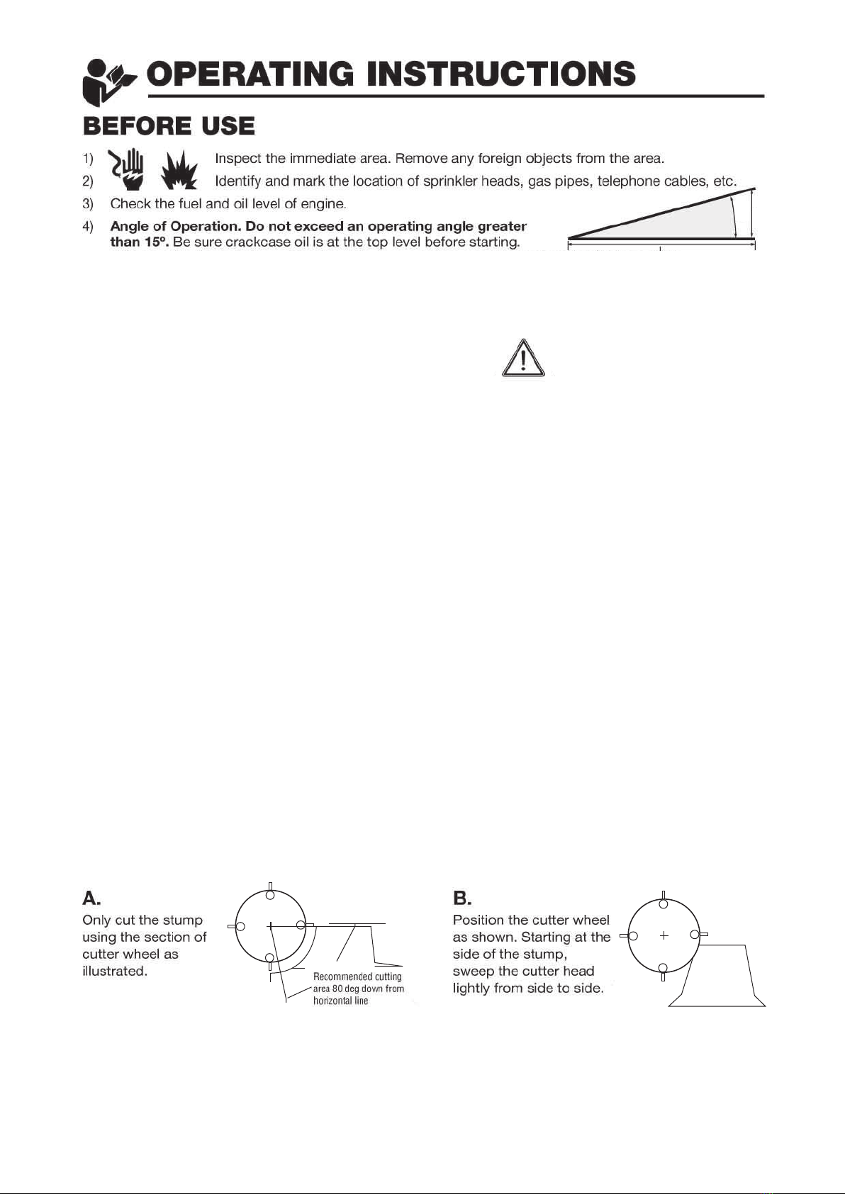
BEFORE USE
1) DO NOT allow any person operate the
rotary hoe without first reading and
understanding the safety instructions and
operating instructions.
2) NEVER allow children to operate the rotary hoe.
8) ALWAYS make certain the Tyne Control Lever is
set at neutral while loading and unloading the
rotary hoe, or moving to and away from working area.
9) NEVER run the machine in reverse while the tynes
are rotating. Always move the tyne control lever to
“OFF” before reversing the wheels.
11) DO NOT leave the machine unattended while the
engine is running.
12) DO NOT overspeed the engine or alter the governor
settings. Excessive speed is dangerous and will
shorten engine life.
13) NEVER operate the rotary hoe in an
enclosed area. Engine exhaust contains
carbon monoxide, an odourless and
tasteless poison.
14) STOP the engine and disconnect the
spark plug lead(s) and allow engine to
cool before inspecting or performing
maintenance on the rotary hoe.
15)
1)
REFUELLING
* Shut off the engine. DO NOT REFUEL
AN ENGINE WHILE OPERATING!
* Allow engine to cool. Minimum 5 minutes
* USE UNLEADED FUEL ONLY.
Use clean, fresh unleaded fuel.
* Do not mix oil with unleaded fuel.
* Do not over-fill fuel tank. Allow space
for fuel expansion.
10) NEVER operate the unit without the safety
guards in place and in working order. Keep
the unit well maintained and in good
working order.
4) ALWAYS use the rotary
hoe in a well lighted area.
7) NEVER operate the rotary hoe when fatigued.
ALWAYS BE ALERT! If you get tired while
operating the rotary hoe, take a break. If you have
any type of physical or mental condition that may
be aggravated by strenuous work, consult with
your physician before you operate this equipment.
NEVER operate the rotary hoe under the influence
of medication, alcohol or drugs.
6) DO NOT allow other persons near the
rotary hoe. It is up to the operator to keep
bystanders and animals a minimum of 6
5) ALWAYS operate the rotary
hoe on level ground only.
Police the area before rotary
hoeing. Remove any foreign objects in the digging
area - bricks, rocks, wire and sticks. Locate and mark
any sprinkler heads, water pipes, gas lines,
electrical and telephone cables or any other hazard
either below or above ground.
3) ALWAYS wear protective clothing when operating
the rotary hoe. This includes, but is not limited to;
safety glasses, loose fitting gloves, steel capped
boots and hearing protection. NEVER wear loose
fitting clothing or jewellery when operating the
rotary hoe. Keep all clothing away from moving
parts. Items could become caught in the machine,
resulting in injury.
KNOW THE CONTROLS AND HOW TO STOP
THE ROTARY HOE QUICKLY IN AN EMERGENCY.
metres (20’) away from the machine while in
operation.
ALWAYS KEEP YOUR HANDS,
FEET AND BODY AWAY FROM
THE DIGGING ZONE WHILE
ENGINE IS RUNNING.
* Do not smoke.
* Allow no naked flame or hot material in refuelling area.
* Use only approved fuel containers and funnels.
Remember, fuel is a potential hazard .
Be sure Tyne Control Lever is set to “Neutral”
while loading and unloading the rotary hoe
and when moving to or from jobsite.
Ensure that all grass and weeds have been cut
as low as possible.
2) If the rotary hoe is to be used in clay or hard
ground conditions, it is recommended to water
the area thoroughly and allow sufficient time
for earth to soften.
3) Police the area. Remove any
foreign objects from the area.
4) Identify and mark the location of sprinkler heads,
gas pipes, telephone cables etc.
“The Right Way to Rent”
You alone know the operational demands and
special conditions affecting the equipment in
your situation and therefore assume the
responsibility for developing, carrying out, and
enforcing the safety concepts which apply to your
own operation to effect the greatest safety for
yourself andthe people around you.
13)
14)
15)
16)
6)
7)
8)
9)
MAXIMUM ANGLE
OF OPERATION
DO NOT EXCEED
15º ANGLE
USE COMMON SENSE
AND PLENTY OF IT
SAFETY INSTRUCTIONS FOR HT912USERS
INSTRUCTIONS
DO NOT allow any person to operate the
hydraulic trencher without first reading and
understanding the safety instructions and
NEVER allow children to operate the hydraulic trencher.
ALWAYS use hydraulic trencher in a well lighted area.
ALWAYS make certain that all control clutches are in
the “disengaged” position prior to starting the engine.
The safety clutch lever/Operator Presence Control on
the left handlebar is for operator protection. DO NOT
tape down or otherwise bypass this Safety Device.
NEVER wear loose fitting clothing or jewellery when
operating the hydraulic trencher. Keep all clothing
away from moving parts. Item could become
caught in the machine, resulting in injury.
ALWAYS wear protective
clothing when operating
the hydraulic trencher.
This includes, but is not limited to, safety glasses, hard hat
loose fitting gloves, steel capped boots and hearing protection.
operating instructions. KNOW THE CONTROLS AND
HOW TO STOP THE HYDRAULIC TRENCHER QUICKLY
IN AN EMERGENCY.
1)
2)
3)
4)
Police the area before trenching. Remove any foreign
objects in the digging area eg bricks, rocks, wire and
sticks. Locate and mark any sprinkler heads, water
pipes, gas lines, electrical and telephone cables or any
other hazard either below or above ground.
5)
DO NOT leave the machine unattended while the engine
is running. DO NOT park on incline or park
perpendicular to slope. DO NOT freewheel down incline.
7)
DO NOT overspeed the engine or alter the governor
settings. Excessive speed is dangerous and will
shorten engine life
8)
NEVER operate the hydraulic trencher when fatigued.
ALWAYS BE ALERT! If you get tired while operating
the hydraulic trencher, take a break. If you have any
type of physical or mental condition that may be
aggravated by strenuous work, consult with your
physician before you operate this equipment. NEVER
operate the hydraulic trencher under the influence of
medication, alcohol or drugs.
9)
NEVER operate the unit without the safety
guards in place and in working order. Keep
the unit well maintained and in good working order
Remove the hydraulic trencher from its
trailer. Use caution.
Police the area. Remove any
foreign objects from the area.
Identify and mark the location of sprinkler heads,
gas pipes, telephone cables, etc.
IGNITION: Must be in “ON” position to start. “OFF”
to stop.
ENGINE: Throttle cable controls engine speed.
Operate at full throttle (all the way forward).
WHEEL DRIVE CONTROL LEVER: Controls wheel
speed forward or reverse after clutch lever is engaged.
DIGGING BOOM CONTROL LEVER: Raises and lowers
the digging boom.
DIGGING CHAIN CONTROL LEVER: must be in “ON”
position BEFORE clutch lever is depressed in order
to start chain in motion. Chain moves in a forward
direction after clutch lever is engaged.
SAFETY CLUTCH LEVER/OPERATOR PRESENCE
CONTROL: (At left handle grip) Activates WHEEL
DRIVE and DIGGING CHAIN controls when depressed.
Stops all motion when released.
FORWARD/REVERSE DIGGING CHAIN CONTROL
LEVER: Allows manual operation of chain in forward
or reverse rotation to dislodge objects or dig difficult
terrain. (This control can be used with the clutch lever
released.) To reverse chain, DIGGING CHAIN control
must be in “OFF” position.
Familiarize yourself with the hydraulic
trencher and its controls.
10)
1)
1)
2)
1)
Free Wheel Hub Feature - Operation:
Pull one free wheeling pin slightly, using the split
ring. Rotate the pin until the 3mm (1/8”) diameter roll
pin aligns with the slot in the mounting plate. Allow
the pin to slide through the slot. Repeat for the other
wheel. Roll the trencher until each pin drops into a
hole in the hub. The wheel hubs are now locked.
Reverse the procedure to unlock the wheels.
2)
DO NOT allow other persons near the hydraulic
trencher. It is up to the operator to keep
bystanders and animals a minimum of 6 metres
(20ft) away from the machine while in operation.
12)
NEVER operate the hydraulic trencher in an
enclosed area. Engine exhaust contains carbon
monoxide, an odourless and tasteless poison.
13)
WARNING: Hydraulic oil is under extreme
pressure and can get under skin and burn
or poison. Check for leaks with cardboard.
14)
STOP the engine and disconnect the spark
plug lead(s) and allow engine to cool before
inspecting or performing maintenance on
the hydraulic trencher.
15)
REFUELLING
* Shut off engine. DO NOT REFUEL AN ENGINE
WHILE OPERATING!
* Allow engine to cool. Minimum 5 minutes
* Do not smoke. *Allow no naked flame
or hot material in refuelling area.
* Use only approved fuel containers and funnels.
Remember, fuel is a potential hazard.
* Do not over-fill fuel tank. Allow space for
fuel expansion.
* USE UNLEADED FUEL ONLY. Use clean,
fresh unleaded fuel.
* Do not mix oil with unleaded fuel.
16)
ALWAYS KEEP YOUR HANDS, FEET AND BODY
AWAY FROM THE DIGGING CHAIN AND OTHER
MOVING PARTS WHILE ENGINE IS RUNNING.
11)
ALWAYS operate
hydraulic trencher
on level ground only.
6) MAXIMUM
ANGLE OF
OPERATION
DO NOT EXCEED 15ºANGLE
BEFORE USE
OPERATION
TRANSPORT
1) DO NOT allow any person to operate the stump grinder without first reading and understanding
the safety and operating instructions. KNOW THE CONTROLS AND HOW TO STOP THE
STUMP GRINDER QUICKLY IN AN EMERGENCY.
2) NEVER allow children or untrained adults to operate the stump grinder.
3) PPE (Personal Protection Equipment) is mandatory before operating this machine. ALWAYS wear
protective clothing when operating the stump grinder. This includes,
but not limited to; safety glasses, loose fitting gloves, steel capped
boots and hearing protection. NEVER wear loose fitting clothing or
jewelry when operating the stump grinder. Keep all clothing away from
moving parts. Clothing could become caught in the machine resulting in injury.
4) ALWAYS operate the stump grinder in a well lit area.
5)
ALWAYS operate the stump grinder on level ground only. Inspect the immediate
area before grinding. Remove any foreign objects in the grinding area eg: bricks,
rocks,wire and sticks. Locate and mark any sprinkler heads, water pipes, gas lines,
electrical and telephone cables or any other hazard either below or above ground.
ALWAYS KEEP YOUR HANDS, FEET AND BODY AWAY FROM THE CUTTING / GRINDING
AREA WHILE ENGINE IS RUNNING
5