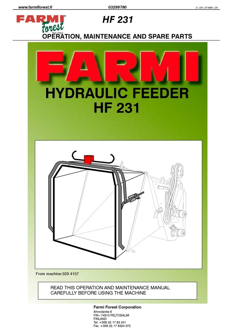
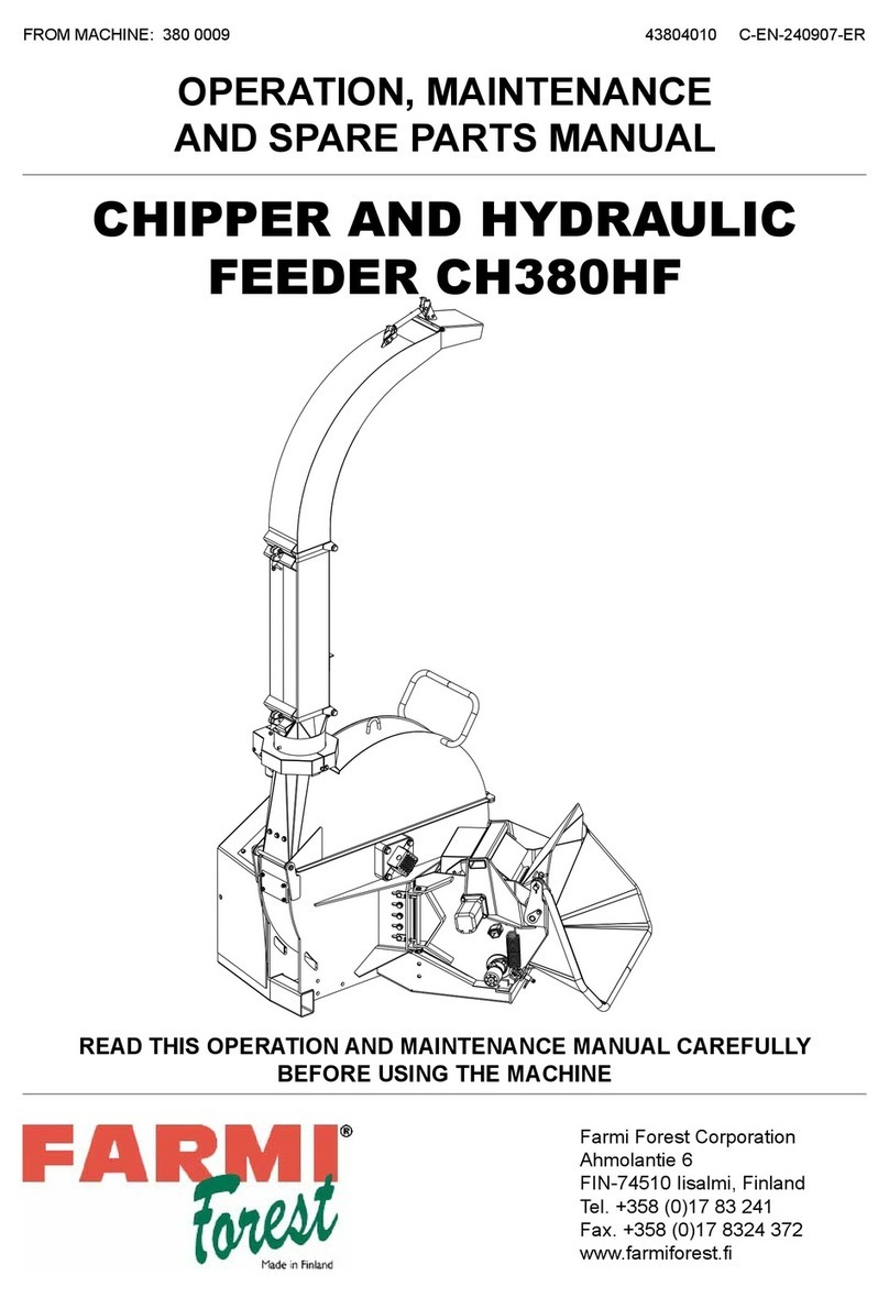
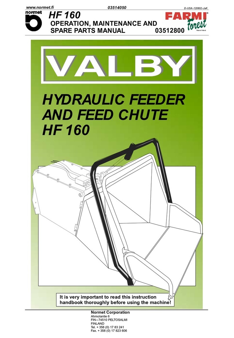
Farmi Forest Corporation VALBY HF 231 Guide

OPERATION, MAINTENANCE AND
SPARE PARTS MANUAL
HF 231
A--USA--200802--JaK
www.normet.fi 03299760
03294709
Normet Corporation
Ahmolantie 6
FIN---74510 PELTOSALMI
FINLAND
Tel.+358(0)1783241
Fa
x
.+358
(
0
)
17 823 606
It is very important to read this instruction
handbook thoroughly before using the machine!
HYDRAULIC FEEDER
ANDFEEDCHUTE
HF231
From machine: 329 4036--


SAFETY INSTRUCTIONS
HF 231
www.normet.fi
03294709
--- 3 ---
1. TERMS AND SYMBOLS USED IN INSTRUCTIONS
Safety is a combination of operator com-
mon sense and alertness at all times
when the machine is being operated or
serviced.
THINK
SAFETY!
This message is used for general remind-
ers of good safety practices or to direct
attention to unsafe practices. The mes-
sage will appear in your operator’s manu-
al and/or the sign will appear on the ma-
chine with the color combination of yel-
low and black.
CAUTION!
This message denotes a specific poten-
tial hazard. The sign will be displayed on
the machine in areas of potential hazard.
The sign will have the color combination
of yellow and black.
WARNING!
This message denotes the most serious
specific potential hazard. The sign will be
displayed on the machine in areas of po-
tential hazard.
DANGER!
Messages labeled ”Important” will ap-
pear in your operator’s manual to provide
specific instructions for performing ad-
justments, services, etc. If these
instruc ---tions are not followed it could re-
sult in damage to the machine.
IMPORTANT!

SAFETY INSTRUCTIONS
HF 231
www.normet.fi
03294709
--- 4 ---
2.SAFETY
2.1.GENERAL SAFETY
IMPORTANT!
Do not operate this machine until you have read and
understood the manual page by page.
The owner of this machine is responsible for
instructing all operators and support personnel in the
operation and safety precautions of this chipper.
Proper training prior to operating the chipper is
obligatory.
D
DD
D
Inform everyone who works with the chipper about the risks and how they can
avoid accidents.
D
DD
D
Before the chipper is running, ensure that the working place is clear of any by-
stander within a minimum risk zone of 100 ft. (30 meter).
D
DD
D
Do not let children or untrained persons operate the chipper.
D
DD
D
Always have the chipper mounted on the 3--point hitch of the tractor. Other-
wise the chipper will tip over.
D
DD
D
There is a serious crushing hazard between tractor and chipper. Do not go be-
tween the tractor and the chipper in any case, for example when you are
mounting the chipper to the tractor.
D
DD
D
Check that the covers of the universal shaft are in their place and the ransmis-
sion chains are fastened.
D
DD
D
Safety goggles, earmuffs and a hard hat are obligatory when chipping. Use
respirator mask, if necessary.
D
DD
D
Do not wear loose clothing, loose sleeves, scarves or long uncovered hair
around moving parts of machinery. Also avoid gloves of poor condition or
with loose fitting, because they might get caught in the branches.
D
DD
D
Stay alert! Do not operate the chipper when fatigued, or under the influence of
alcohol or drugs.
D
DD
D
IMPORTANT! Never leave the chipper running and unattended.
D
DD
D
IMPORTANT! Failure to obey the warnings on the chipper or in the operator’s
manual will result in personal injury and / or death and / or equipment dam-
age.
D
DD
D
Check the material before you feed it. The material must be free from nails,
stones and all other materials that are not wood, paper or plastic. IMPOR-
TANT! Feeding wire and barbed wire into the chipper is very dangerous as it
might pull in the operator.
D
DD
D
Make sure that no one is in the path of flying chips. Point the discharge pipe
away from windows, doorways and other areas where people or animals may
be.
D
DD
D
Keep the work area clean so there is nothing to trip over.
SAFETY INSTRUCTIONS
HF 231
www.normet.fi
03294709
--- 5 ---
D
DD
D
Disengage the PTO, cut the engine and remove the keys before any mainte-
nance.
D
DD
D
Use only original parts replacements. IMPORTANT! Do not make any modifica-
tions.
D
DD
DCheck all moving parts. They should be fastened in place, in good working
condition and all shields and guards must be in place.
D
DD
DPoint the discharge downwind to prevent dust or chips from blowing onto
the operator.
D
DD
DIf a wood jams inside the chipper, cut the engine and wait for all movements
to stop before reaching inside the feed chute.
D
DD
D
Do not use the chipper indoors when you use it with a the tractor or with the
separate hydraulic motor. It’s possible to use the chipper indoors with the
electric motor use.
D
DD
D
You must be very careful when working indoors. Protect yourself against pos-
sible hazards like exhaust gas by sufficient ventilation, for dust that can catch
fire by cleaning your environment regularly.
D
DD
D
Always use the lock bolt before and during maintenance on the machine.
D
DD
D
Place the PTO shaft in the holding device when disconnected from tractor.
Risk of cutting injury or hits by flying debris.
Do not reach into the feed chute for any reason.
Failure to follow these instructions could result in serious
injury or death.
Danger!
2.2.SAFETY INSTRUCTIONS FOR THE HYDRAULIC FEEDER AND FEED CHUTE
D
DD
DIMPORTANT! Always also read the general safety instructions.
D
DD
DIMPORTANT! Do not ever put any part of your body inside the feed chute!
D
DD
DPrior to operating get familiar with the function and controls of the machine.
All functions must be in blameless condition.
D
DD
DTest the stop function.
D
DD
DBefore starting up, check that there is no debris or foreign objects in the
feed chute.
D
DD
DDo not work in front of the feed chute opening! Stand on the left side of the
chute when feeding, as the feed roller might jerk the wood up or to the right.
D
DD
DWhen checking malfunction, all controls must be in ”off” or in ”stop” posi-
tion.
D
DD
DLet go of the wood when the feed roller or the knives get hold of it. To feed
short pieces, push them in with longer ones.

SAFETY INSTRUCTIONS
HF 231
www.normet.fi
03294709
--- 6 ---
2.3.SAFETY INSTRUCTIONS FOR THE HYDRAULIC UNIT
D
DD
DBefore performing lubrication work on any equipment, consult the manufac-
turer’s instruction manual and follow the recommended procedures.
D
DD
DBefore lubricating the machine, shut down the engine and stop the ma-
chine.
D
DD
DPressurized oil can be hazardous. Pressurized oil jet can penetrate skin and
cause serious injuries or death.
D
DD
DOccasional skin exposure with oil is not dangerous. If though you can not
prevent long ---time exposure use protective gloves and other protective
clothing.
D
DD
DKeep flammable material away from heat, sparks and open fire.
D
DD
DHot oil and oil spray can be hazardous. Small amounts swallowed or inhaled
do not usually cause toxication. Old oil is more dangerous than new.
D
DD
DIf oil has got into eyes flush them with cool water after which go to doctor.
Use safety goggles.
D
DD
DAvoid mixing lubricants of different grade and quality. Use only recom-
mended oils or oils with corresponding characters.
2.4.SAFETY INSTRUCTIONS FOR THE SEPARATE HYDRAULIC MOTOR USE
D
DD
D
Check the moving parts. They should be fastened in place, in good working
condition and all shields and guards must be in place.
D
DD
D
Inform everyone who works with the chipper about the risks and how they can
avoid accidents.
D
DD
D
Do not let children or incapable persons operate the chipper.Do not wear loose
clothing, loose sleeves, neckties or long uncovered hair around moving parts
of machinery.
D
DD
D
Disengage the PTO and turn the tractor off before you service the chipper.
D
DD
D
Use only original parts replacements. Do not make any modifications.
D
DD
D
Failure to obey the warnings printed on the chipper or in the operator’s manual
might result in a serious injury or death.
D
DD
D
When checking the malfunction, all devices must be in “off” position.
D
DD
D
Place the PTO shaft in the holding device when disconnected from tractor.

TABLE OF CONTENTS
HF 231
www.normet.fi
03294709
--- 7 ---
1. TERMS AND SYMBOLS USED IN INSTRUCTIONS 3........................
2. SAFETY 4...............................................................
2.1. GENERAL SAFETY 4..............................................................
2.2. SAFETY INSTRUCTIONS FOR THE HYDRAULIC FEEDER AND FEED CHUTE 5..........
2.3. SAFETY INSTRUCTIONS FOR THE HYDRAULIC UNIT 6...............................
3. FEED CHUTE PRESENTATION 9..........................................
3.1. FIELD APPLICATION 9.............................................................
3.2. MAIN COMPONENTS 9............................................................
3.3. TECHNICAL DATA 10..............................................................
4. ASSEMBLY AND MOUNTING 11...........................................
5. CHANGING THE VALVE FOR THE CLOSED CENTRE HYDRAULICS 11.......
6. OPERATION 13..........................................................
7.1.CONTROLS 13.....................................................................
7.2.OPERATION 13.....................................................................
7.3.ADJUSTING THE FEED SPEED 13....................................................
8. MAINTENANCE 14.......................................................

TABLE OF CONTENTS
HF 231
www.normet.fi
03294709
--- 8 ---
SPARE PARTS
03294709 HF 231 Hydraulic feed chute 16.. ................................
03294725 Hydraulics 18.. .................................................
56046154 Control valve, complete 22.. ....................................
--- 56046204 Inlet section 23..............................................
--- 58101551 Work section 24.............................................
--- 56040215 Outlet section, new model 25................................
--- 56040215 Outlet section, old model 26.................................
WHEN ORDERING SPARE PARTS, PLEASE INDICATE MACHINES TYPE FROM THE MACHINE PLATE,
SPARE---PARTS ORDER NUMBER, DESCRIPTION AND QUANTITY REQUIRED.
EXAMPLE: HF231, 23292105, Upper feed roller, 1 pcs.
Thread Millimeter Inch
M6 10 7/16
M8 13 1/2
M10 17 11/16
M12 19 3/4
M16 24 15/16
M20 30 13/16

PRESENTATION
HF 231
www.normet.fi
03294709
--- 9 ---
3. FEED CHUTE PRESENTATION
3.1. FIELD APPLICATION
The hydraulic feed chute HF231 makes feeding
difficult material easier and more effective. The
chip quality improves due to constant feeding
speed and is less dependent on knives sharp-
ness.
The HF231 can be driven by the tractor hydraulics
or by the optional independent hydraulic unit
HD11.
HF231 is easily mounted to the same attachment
as the mechanical feed chute and the drop spout.
3.2. MAIN COMPONENTS
1.Control lever
2.Directional valve
3.Flow regulator
4.Hydraulic motors
5.Feed rollers
6.Frame
7.Chute
1. 2.3.
4.5.7.
6.
Fig.1. HF 231 main parts.

PRESENTATION
HF 231
www.normet.fi
03294709
--- 1 0 ---
3.3. TECHNICAL DATA
Feed roller 2pcs.Æ208 mm (11”)
Max. tree diameter 250 mm (10”)
Hydraulic motor 2 pcs. 250 cm
3
Oil demand, P.T.O speed
chip 20 mm, 540 rpm.
chip 20 mm, 1000 rpm.
30l/min(8USgal/min.)
52 l/min (13
2
/
3
US gal/min.)
Feed chute opening size 820 mm x 787 mm (32.3” x 31”)
Weight 210kg(463lb)

ASSEMBLY AND MOUNTING
HF 231
www.normet.fi
03294709
--- 1 1 ---
4. ASSEMBLY AND MOUNTING
1.Fasten the frame of the hydraulic feed to the
chipper with two hinge pins. See fig.2.
Fig.2.
2.Fasten the feed chute to the frame with two
hinge bolts (M10x110 screws and M10 lock-
nuts) and lock it into working position. Fig.3.
Fig.3.
3.Hook up the control rods extension with the
pin.
4.Connect hydraulic hoses; Connect pressure
hose (marked ”IN”) to tractors hydraulic con-
nection. Maximum pressure is 172 bar (2500
PSI).
Connect return hose (marked ”OUT”) either
to double--acting hydraulic valves return hose
hook--up, or in a single acting system directly
to the oil reservoir. Fig.4.
IN
OUT
Fig.4. Connecting the hydraulics.
5. CHANGING THE VALVE FOR
CLOSED CENTRE
HYDRAULICS
DThe chippers valve is built for open center
hydraulics. If your tractor has a closed centre
hydraulic system, can the valve be changed
to suit your system by changing the plug at
the end of the valve. See fig.5.

ASSEMBLY AND MOUNTING
HF 231
www.normet.fi
03294709
--- 1 2 ---
Before change
After change
Plug
Serial nipple
order no. 52435732
Plug
order no.52080207
Pressure
IN
Return
OUT
Fig.5. Changing the valve for closed center
hydraulics.
DInstructions for connecting the hydraulics
when using the optional hydraulic unit can be
found in hydraulic units mounting instruc-
tions.

OPERATION AND MAINTENANCE
HF 231
www.normet.fi
03294709
--- 1 3 ---
6. OPERATION
6.1. CONTROLS
HF231 is operated with an operating handle which
has three positions: FEEDING, STOP and
REVERSE. Fig.6.
REVERSE
STOP
FEEDING
Fig.6. Controls
6.2. OPERATION
1.Ensure that the feed chute is empty. Turn the
tractor hydraulics on.
2.Before feeding make sure that the tree is free
from stones, nails and other foreign objects.
3.If necessary adjust feedrollers rotation speed
to match the speed of the disc.
4.Pull the operating handle to FEEDING posi-
tion. Feedrollers start rolling when all air in
hydraulic circuit has been displaced.
5.Push the tree trunk inside the chute. Let go of
the tree as soon as the feedroller gets hold of
it.
Don’t work too close to the
feeding chute. The tree might
jerk up or to the right when it
comes into contact with the
teeth of the roller.
DANGER!
DWhen chipping large wood with a weak trac-
tor, can the tractor’s speed of rotation sink too
much. Interrupt the feeding by pushing the
control rod to STOP position. When the
speed of rotation has increased enough, con-
tinue feeding by pushing the rod to FEED
position.
DIn case you must remove the tree from the
feed chute during chipping, push the rod to
REVERSE position and keep it there until the
feedrollers release the tree. The rod returns
itself to STOP position.
Oil is heating up when it flows
through the hydraulic motor.
Heating occurs especially if the
tractor has a very small hydrau-
lic oil reservoir. Check twice
everyhourtopreventtheoil
from overheating. Let the trac-
tor cool off if the motors are hot
CAUTION!
6.3. ADJUSTING THE FEEDING
SPEED
DAdjust feedrollers rotational speed to match
the speed of the disk with the oil control valve.
Turning counter--clockwise increases the
feedrollers speed. Fig.7.
Fig.7.
DSpeed is suitable when the wood doesn’t
push against the flange of the disk, or the fee-
droller doesn’t noticeably slow the feeding of
the wood. See table below.
CHIP SIZE FEEDROLLERS
ROTATING SPEED
mm inch rpm rps
71/4” 18 0,30
15 5/8” 39 0,65
22 7/8” 57 0.95

OPERATION AND MAINTENANCE
HF 231
www.normet.fi
03294709
--- 1 4 ---
7. MAINTENANCE
DAll bearings in the feed system are perma-
nently lubricated and do not need any further
lubrication.
DCheck and tighten possibly loose screws and
nuts often.
DTake care that the oil in the hydraulic system
is clean. Dirt may damage valves and hydrau-
lic motors.

--- 1 5 ---

SPARE PARTS
HF 231
www.normet.fi
03294709
--- 1 6 ---
03294709 HF 231 Hydraulic feeder chute

SPARE PARTS
HF 231
www.normet.fi
03294709
--- 1 7 ---
03294709 HF 231 Hydraulic feeder chute
Part Order no. Description Remarks Qty.
1 13291562 Frame 1..... ..... ...........................................................
2 13291802 Roller frame 1..... ..... ......................................................
3 33291873 Frame bracket right 1..... .... ................... ............................
4 43293786 Frame bracket left 1..... .... ................... .............................
5 33291931 Motor fastening bracket 1..... ..... ............................................
6 43291962 Rubber shield 2..... ..... ....................................................
7 43291970 Shield fastener 4..... ..... ...................................................
8 43291988 Upper roller support 1..... ..... ...............................................
9 43292002 Lower roller support 1..... ..... ...............................................
10 43291996 Spring lever 1.... ..... ......................................................
11 23292048 Lower feed roller 1.... ..... ..................................................
12 23292105 Upper feed roller 1.... ..... ..................................................
13 54511431 Ball bearing 6004 2RS 2.... ..... ..................... .......................
14 52230034 External retaining ring 2.... ..... .............................................
15 52090438 Socket head cap screw M10x 20 DIN 7991 4.... ..... ........... ...............
16 43295831 Control handle 1.... ..... ....................................................
17 43292184 Control extension 1.... ..... .................................................
18 43292192 Control rod 1.... ..... .......................................................
19 52842135 Hair pin Æ4x80 1.... .... ......................... ........................
20 52117124 Lock nut M12 DIN985 3.... ..... ........................ .....................
21 54561022 Bushing MB2015 DU 2.... ..... ........................ .....................
22 52110046 Nut M10 DIN934 9.... ..... ............................ .....................
23 52211042 Spring washer M10 DIN 127 6.... ..... ................... ....................
24 52060332 Hex. screw M10 x 110 DIN931 2.... ..... ...................... ...............
25 23295678 Feed chute extension 1.... ..... ..............................................
26 52117108 Lock nut M10 DIN985 1.... ..... ........................ .....................
27 94617073 Spring 1.... ..... ...........................................................
28 52200045 Washer M10 DIN126 4.... ..... ......................... .....................
29 52200052 Washer M12 2.... ..... ......................... ............................
30 33297380 Plate 1.... ..... ............................................................
31 52062023 Bolt M12 x 30 DIN933 4.... ..... ............................ ................
32 52211059 Spring washer M12 DIN 127 4.... ..... ................... ....................
33 52110053 Nut M12 DIN934 2.... ..... ............................ .....................
34 52110020 Nut M6 DIN934 9.... ..... ............................ ......................
35 52060225 Bolt M10 x 25 DIN933 4.... ..... ............................ ................
36 43292325 Ring 2.... ..... ............................................................
37 52832102 Rivet 4,8 x 15 3.... ..... ........................... .........................
38 52060381 Bolt M6 x 12 DIN933 6.... ..... ............................ ..................
39 52090743 Socket head cap screw M10 x 35 DIN7991 6.... ..... ........... ...............

SPARE PARTS
HF 231
www.normet.fi
03294709
--- 1 8 ---
03294725 Hydraulics
44
46

SPARE PARTS
HF 231
www.normet.fi
03294709
--- 1 9 ---
03294725 Hydraulics
Part Order no. Description Remarks Qty.
1 56001951 Hydraulic motor 2..... ..... ..................................................
2 56046154 Valve, complete See separate spare parts list 1..... ..... .................. .......
3 56070162 Equalizer valve 1..... .... ...................................................
4 56524259 Hose S1/2S L=2,0 m 2..... ..... ........................... ...................
5 52432051 Adapter R1/2--R1/2 7..... ..... ......................... ......................
6 52390382 Copper ring 1/2” 9..... ..... ..................... ............................
7 52449022 Quick coupler 1/2” male 2..... ..... ................... ........................
8 52390390 Coupler ring 3/4” 2..... ..... ..................... ............................
9 52432044 Double nipple 3/4”--1/2” 2..... ..... ................... ........................
10 52432010 Double nipple 1/2”--3/8” 2.... ..... ................... ........................
11 52390374 Copper ring 3/8” 2.... ..... ..................... ............................
12 52435062 Extension nipple R1/2”--R1/2” 1.... ..... ................. .....................
13 52443132 T--nipple RK1/2”-- R1/2” 1.... ..... ........................ ...................
14 56526197 Hose S1/2”K L=1,4 m 2.... ..... ........................... ..................
15 56526114 Hose S1/2”K L=0,8 m 2.... ..... ........................... ..................
16 --....
17 --....
18 --....
19 --....
20 --....
21 --....
22 --....
23 --....
24 --....
25 --....
26 --....
27 --....
28 --....
29 --....
30 --....
31 --....
32 --....
33 --....
34 --....
35 54922141 Cap 2.... ..... .............................................................
36 --....
37 --....
38 --....
39 --....
40 --....

SPARE PARTS
HF 231
www.normet.fi
03294709
--- 2 0 ---
03294725 Hydraulics
44
46
Other manuals for VALBY HF 231
1
Table of contents
Other Farmi Forest Corporation Farm Equipment manuals

Farmi Forest Corporation
Farmi Forest Corporation CH380HF Guide

Farmi Forest Corporation
Farmi Forest Corporation VARIO 101 Guide

Farmi Forest Corporation
Farmi Forest Corporation VALBY HF 160 Guide

Farmi Forest Corporation
Farmi Forest Corporation VALBY HF 231 Guide

Farmi Forest Corporation
Farmi Forest Corporation 90 Guide

Farmi Forest Corporation
Farmi Forest Corporation 100 Guide