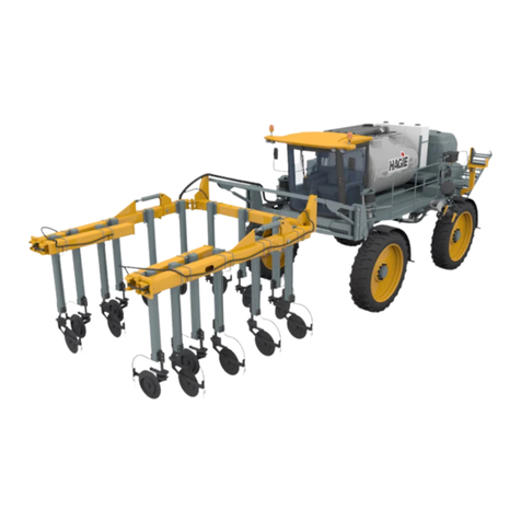
Hagie DTS 10 User manual

TABLE OF CONTENTS
5 - DASH / AUTO
Covers Machine Serial Numbers: SNU14011515001-200 Part No. 493617
© 2014-15 Hagie Manufacturing Company. Clarion, Iowa USA Rev. 15C150320
1 – INTRODUCTION
A Word From Hagie Manufacturing Company ................................................................................ 1-1
About This Manual ........................................................................................................................... 1-1
Safety Messages Used In This Manual ............................................................................................. 1-2
Service and Assistance ...................................................................................................................... 1-2
Reporting Accidents, Injuries, or Safety Concerns ........................................................................... 1-2
Identification ..................................................................................................................................... 1-2
Specifications .................................................................................................................................... 1-5
2015 Product Warranty ................................................................................................................... 1-15
2 – SAFETY AND PRECAUTIONS
Intended Use ..................................................................................................................................... 2-1
Safety Precautions ............................................................................................................................. 2-1
Seat Belt ............................................................................................................................................ 2-6
Emergency Exit ................................................................................................................................. 2-6
Safety Decals .................................................................................................................................... 2-6
3 – CAB
Seat - Operator (Air Suspended) ....................................................................................................... 3-1
Operator’s Station ............................................................................................................................. 3-2
4 – ENGINE AND DRIVE SYSTEMS
Engine - Starting ............................................................................................................................... 4-1
Engine Monitor - Cantrak 2600 ........................................................................................................ 4-2
Hydrostatic Drive .............................................................................................................................. 4-3
5 – HYDRAULIC SYSTEMS
Hydraulic System .............................................................................................................................. 5-1
Tread Adjustment - Hydraulic .......................................................................................................... 5-1
6 – ELECTRICAL SYSTEMS
Batteries ............................................................................................................................................ 6-1
Battery Disconnect Switch ................................................................................................................ 6-2
Fuses and Circuit Breakers ............................................................................................................... 6-3
7 – SPRAY SYSTEMS
Spray Booms - 60/80/90’ .................................................................................................................. 7-1
Solution System Components ........................................................................................................... 7-6
Solution System - Operation ........................................................................................................... 7-11
Fence Row Applicator .................................................................................................................... 7-13
Filling Your Solution Tanks ........................................................................................................... 7-14
Rinse System ................................................................................................................................... 7-15
Foam Marker System ...................................................................................................................... 7-18

TABLE OF CONTENTS
Application ...................................................................................................................................... 7-20
8 – MAINTENANCE AND STORAGE
Service - Fluids ................................................................................................................................. 8-1
Service - Filters ................................................................................................................................. 8-7
Service - Lubrication ...................................................................................................................... 8-11
Service - Belts ................................................................................................................................. 8-14
Service - Bolt Torque ...................................................................................................................... 8-14
Service - Toe-In .............................................................................................................................. 8-16
Service - Tires ................................................................................................................................. 8-17
Service - Tread Adjust Shims ......................................................................................................... 8-17
Service - Drive Train ...................................................................................................................... 8-18
Service - Roof Access ..................................................................................................................... 8-19
Service - Miscellaneous .................................................................................................................. 8-20
Service Intervals ............................................................................................................................. 8-23
Storage ............................................................................................................................................ 8-25
9 – MISCELLANEOUS
Transporting ...................................................................................................................................... 9-1
Wheel Tread and Row Spacing ........................................................................................................ 9-3
Hand Wash System ........................................................................................................................... 9-5
Troubleshooting ................................................................................................................................ 9-7

1-1
5 - DASH / AUTO
SECTION 1 – INTRODUCTION
The following patent decal is located on the
rear left-hand frame and provides current patents
issued on your machine.
NOTE: Hagie Manufacturing Company reserves
the right to make changes to any current
patents or patents pending at any time,
without notice.
A WORD FROM HAGIE
MANUFACTURING COMPANY
Congratulations on the purchase of your
DTS10 Sprayer! We recommend that you review
this operator’s manual and become familiar with
operating procedures and safety precautions
before attempting to operate your machine.
As with any piece of equipment, certain
operating procedures, service, and maintenance
are required to keep your machine in top running
condition. We have attempted herein to cover all
of the adjustments required to fit varying
conditions. However, there may be times when
special care must be considered.
NOTE: The user is responsible for inspecting the
machine and having parts repaired or
replaced when continued use of the
product causes damage or excessive
wear to other parts.
Hagie Manufacturing Company reserves the
right to make changes in the design and material
of any subsequent machine without obligation to
existing units.
Thank you for choosing a Hagie sprayer and
we ensure you of our continued interest and
support in its optimal performance for you. We
are proud to have you as a customer!
ABOUT THIS MANUAL
This manual will aid you in the proper
operation and service of your machine. It is the
responsibility of the user to read the operator’s
manual and comply with the correct and safe
operating procedures, as well as maintain the
product according to the service information
providedintheMaintenanceandStorageSection
elsewhere in this manual.
Photographs and illustrations used in this
manual are of general nature only. Some of the
equipment and features shown may not be
available on your machine.
Information described in this manual was
correct at the time of printing. Because of Hagie
Manufacturing Company’s continuous product
improvement, certain information may not be
included in this manual. To obtain the most
current operator’s manual for your machine,
please visit www.hagiehelp.com.
Hagie Manufacturing Patent Decal
(Located on the rear left-hand frame)
NOTICE
Any pictures contained within this
operator’s manual that depict situations
with shields, guards, rails, or lids
removed are for demonstration only.
HagieManufacturingCompanystrongly
urges the operator to keep all shields
and safety devices in place at all times.

SECTION 1 –
INTRODUCTION
1-2
Keepthis manual in a convenientplace for
easy reference. This manual is considered a
permanent fixture of the product. In the event
of resale, this manual should accompany the
machine.
If you do not understand any part of this
manual or require additional information or
service, contact Hagie Customer Support for
assistance.
SAFETY MESSAGES USED
IN THIS MANUAL
The following safety messages found
throughout this manual alert you of situations
that could become potentially dangerous to
the operator, service personnel, or
equipment.
NOTE: A “Note” is intended to make special
mention of, or remark on.
SERVICE AND ASSISTANCE
For service and assistance, please contact:
Hagie Manufacturing Company
721 Central Avenue West
P.O. Box 273
Clarion, IA 50525-0273
(515) 532-2861 OR (800) 247-4885
www.hagiehelp.com
REPORTING ACCIDENTS,
INJURIES, OR SAFETY
CONCERNS
Should an accident or injury occur
involvingtheuseofa Hagie product,orifyou
have a product safety concern, report such
information directly to Hagie Customer
Support at (800) 247-4885.
IDENTIFICATION
Each machine is identified by means of a
frame serial number. This serial number
denotes the model, year in which it was built,
and the number of the sprayer.
DANGER
This symbol indicates a hazardous
situationwhich, ifnotavoided,will result
in serious injury or death.
WARNING
This symbol indicates a potentially
hazardous situation which, if not
avoided, could result in moderate/
serious injury or death.
CAUTION
This symbol indicates a potentially
hazardous situation which, if not
avoided, may result in minor or
moderate injury. It may also be used to
alert against unsafe practices.
NOTICE
This symbol indicates operator
awareness which, if not avoided, may
result in personal or property damage.
NOTICE
Reference to right and left-hand used
throughout this manual refers to the
position when seated in the operator’s
seat facing forward.

1-3
SECTION 1 –
INTRODUCTION
For further identification, the engine and
hydrostatic pumps each have serial numbers,
the wheel motors have identification tags,
and the planetary wheel hubs have
identification plates that describe the type of
mount and gear ratio.
To ensure prompt, efficient service when
ordering parts or requesting service repairs,
record the serial numbers and identification
numbers in the following spaces provided.
Sprayer
The sprayer serial number is stamped on
the right-hand side of mainframe.
Engine
The engine has an identification plate
located on the side of the front left-hand gear
housing that provides engine serial number,
as well as other manufacturer information.
Refer to your Parts Manual for specific part
number.
Hydrostatic Pumps
The tandem hydrostatic pumps (front and
rear) each have an identification plate located
on the front side of each pump. Refer to your
Parts Manual for specific part number.
Wheel Motors
The wheel motors each have an
identification plate mounted on the side of
motor that provides motor serial number, as
well as other manufacturer information.
Refer to your Parts Manual for specific part
number.
Sprayer Serial Number
-Typical View
Serial No. _______________________
Engine Identification Plate
-Typical View
Serial No. _______________________
Hydrostatic Pump Identification Plates
-Typical View
Front _______________________
Rear _______________________

SECTION 1 –
INTRODUCTION
1-4
Wheel Hubs
The wheel hubs each have an
identification plate mounted on the front of
hub that provides hub serial number, as well
as other manufacturer information, including
gear ratio. Refer to your Parts Manual for
specific part number.
Wheel Motor Identification Plates
-Typical View
Left Front: ____________________
Right Front: ___________________
Left Rear (w/sensor): _________________
Right Rear (w/o sensor): _______________
Front Wheel Motor Rear Wheel Motor
Wheel Hub Identification Plate
-Typical View
_______________________ Right Front
_______________________ Right Rear
_______________________ Left Front
_______________________ Left Rear

1-5
SECTION 1 –
INTRODUCTION
SPECIFICATIONS
NOTE: 90-ft. boom and 290/95 R34 tires used for the following machine dimensions.
Detail Description Specification
A Overall Machine Height**
NOTE: Sprayer height does not include the cab-
mounted optional GPS unit.
• 133”/337.8 cm (from top of cab)
• 152”/386.1 cm (from top of boom)
B Raised Transom Height** 134” (340.4 cm)
C Transom Lift Range 22.25” - 99.75” (56.5 - 253.4 cm)
(77.5”/196.9 cm range)
D Static Loaded Hub Height** 26” (66 cm)
E Wheel Base 140” (355.6 cm)
F Sprayer Length 322” (817.9 cm)
G Rear Handrail Height 121” (307.3 cm)
H Width (booms folded, 120” tread) 152”/386.1 cm (from tank to tank)
I Frame Clearance** 66.5” (168.9 cm)
J Center Clearance** 64.75” (164.5 cm)
K Lower Leg Clearance** 20.5” (52.1 cm)
L Tire (center to inside of lower leg) 14.5”/36.8 cm (rear)
M Tread Width**
Optional 120”-144” (304.8 - 365.8 cm) - adjustable*
120” - 154” (304.8 - 391.2 cm) - adjustable*

SECTION 1 –
INTRODUCTION
1-6
* Tread width is measured at half (1/2) the tire
height.
General Information
•Frame Type:
3 x 6” (7.6 x 15.2 cm) modular platform
frame
•Suspension:
Rigid, 4-wheel, independent air bags
•Shipping Width:
152”/386.1 cm (at 120”/304.8 cm tread
width)
•Approximate Dry Weight:
15,500 lbs. (7,030 kg)
NOTICE
Because Hagie Manufacturing
Company offers a variety of options, the
illustrations in this manual may show a
machine equipped other than standard.
Height and weight do not consider
options. Values may vary, depending on
available equipment.

1-7
SECTION 1 –
INTRODUCTION
Spray System GPS Specifications
-If Equipped
NOTE: 90-ft. boom and 290/95 R34 tires used for the following machine dimensions.
NOTE: Dimensions may vary depending on
boom and tire options.
Detail Description Specification
A Wheel Base 140” (355.6 cm)
B Static Loaded Hub Height 26” (66 cm)
C Overall Sprayer Height (from middle of GPS unit) 138.5” (351.8 cm)
D Length
(from front of boom spray tips to center of GPS unit) 164” (416.6 cm)
E Length (from center of GPS unit to center of rear hub) 84” (213.4 cm)

SECTION 1 –
INTRODUCTION
1-8
Settings and Calibration
Record settings and calibration values
used in the following spaces provided when
programming your spray system console.
Refer to this information for future reference.
Circle the selected setting on the spray system console for the following options:
Record calculated calibration values in the spaces provided below.
Units • US (Acres) • SI (Hectares) • Turf
(1,000 sq. ft./
92 sq. m)
Speed
Sensor • SP1 (Wheel Speed) • SP2 (Radar/GPS)
Control Type • Liquid Spray • Gran 1
(Single Belt
Bed)
• Gran 2
(Split Belt
Bed/Single
Encoder)
• Gran 3
(Split Belt
Bed/Dual
Encoders)
• Spinner RPM
Control
Valve Type • Standard
Valve • Fast Valve • Fast Close
Valve •PulseWidth
Modulated
Valve
•PulseWidth
Modulated
Close Valve
Speed Cal Section
Widths Meter Cal Rate Cal Valve Cal Tank Volume
1. 1. 1. 1. 1. 1.
2. 2. 2. 2. 2.
3. 3. 3. 3. 3.
4. 4. 4. 4. 4.
5. 5. 5. 5. 5.
6.
7.
8.
9.
10.

1-9
SECTION 1 –
INTRODUCTION
Description Specification
Engine
Manufacturer Cummins®
Model 6BTA 6.7 QSB (turbo charged)
Type In-Line, Liquid Cooled
Number of Cylinders 6
Displacement 6.7 Liter (408.9 c.i.)
Horse Power 215 (intermittent)
Fuel Type No. 1 or 2 Diesel
Fuel System Filtered, Direct-Injected
Air Cleaner Dry-Type, Dual Element
Slow Idle 800 RPM
Fast Idle 2720 RPM (no load)
Power Train
Hydrostatic Pump Danfoss Tandem 90-Series
Range 132cc (66x2), Limited Stroke
(variable displacement)
Drive Train All-Time 4-Wheel Drive
Speed (depending on tire size)
•Low
•Medium
• High
• 0-14 mph (0-22 km/h)
• 0-18 mph (0-30 km/h)
• 0-28 mph (0-45 km/h)
Hydrostatic Wheel Motor (Front/Rear) Danfoss M46
Final Drives
• Type
- Front/Rear
•Lubrication
• Planetary Gear Reduction Hubs
• Torque Hub® 7000-Series (7HBA and 7HBX)
• Oil Bath
Brakes
• Type Integral, Spring-Applied, Hydraulically Released
Steering
• Type
• Control
• Steering Cylinders
• Turning Radius (120”/304.8 cm tread setting)
• Hydraulic, Priority on Demand
• Full-Time Power
• Self-Centering, Double Action
• 19.5” (49.5 cm)
Auxiliary Hydraulic System
Type Open
Pump Type Tandem Gear

SECTION 1 –
INTRODUCTION
1-10
Pressure Setting 2600 PSI (179.3 bar)
Spray System
Booms
• Type
• Standard
• Optional
• Controls
• Hydraulic Level Shock Absorber
• Dry (with variable row spacing)
• 60-ft. (3 spray sections)
• 60/80-ft. or 90-ft. (5 spray sections)
• Electro-Hydraulic, Fold/Lift/Level
• Boom Level Accumulator
Hoses
• Rear Fill Connection (Male w/Female Adapter)
• Solution Hose from Tank
• Boom Section Feeder Hose
• Boom Nozzle Hose
• 2” (5.1 cm) I.D.
• 1.5” (3.8 cm) I.D.
• 1” (2.5 cm) I.D.
• .75” (1.9 cm) I.D.
Solution Tanks
• Standard
• Agitation
• (2) 500 Gallon (1892 L) Polyethylene Tanks
with Sight Gauge
• Mechanical, Hydraulically Driven w/Variable
Speed Control
General Spray System
•Pump
• Solution Valves
• Pressure Gauge
•Monitor
• Fence Row Nozzle
• Centrifugal, Hydraulically Driven with Variable
Speed Control
• Electric Ball Valves
• Glycerin Filled (100 PSI/6.9 bar)
• Raven 4600 (GPS ready)
• Standard
Foam Marker System
Make Hagie Foam Marker
Type Live Air
Rinse System
Spray System Rinse
(Solution Tanks, Pump, Booms) Standard
High-Pressure Wash System Optional
Electrical System
General Electrical System
• Battery
• Alternator
•Starter
• Single 12V, Negative Ground
• 130 AMP, Voltage Regulated
• 12V with Solenoid
Circuit Breakers
• Main Breaker
• Starter Relay
• Highway/Field Lights
• Work Lights
• Foam Marker/Switch Panel Auxiliary Power
• A/C and Storage Console Auxiliary Power
•Engine
•100AMP
•30AMP
•40AMP
•30AMP
•30AMP
•30AMP
• 125 AMP (2x)

1-11
SECTION 1 –
INTRODUCTION
Fuses
• Rinse System Power/Gauges
• Hydraulic Tread Adjust/Seat
• Spray Solution Valves
• Flow Control/Agitation/Boom Folding Controls
• Fuel/Brake
•AM/FMRadio
• CB Radio Power Supply/Dome Light
• Tank Solution Valves/Rinse System Control
• Hazard/Warning Lights, Turn Signals, Wiper
• Boom Lift/Level Controls
•10AMP
•20AMP
•10AMP
•10AMP
•15AMP
•10AMP
•10AMP
•10AMP
•10AMP
•15AMP
Lights
•FrontCab
•RearCab
•Booms
• Tank Shields
• (4) Trapezoidal Field Lights
• (2) Trapezoidal Work Lights
• (2) Trapezoidal Work Lights (1 each)
• (2) Trapezoidal Highway Lights (1 each)
Auxiliary Power Supplies
• Switch Panel 12V Binding Post-Type
Cab and Instruments
General Cab • Tilt Steering
• Windshield Wipers/Washer
• Flashing Hazard Warning Lights
• Turn Signals
•SideMirrors
• Dome Light
• Tinted Glass
Temperature Control Full Range
A/C Charge Type R-134a
Fresh Air Filtration Paper and Charcoal Filters
Seat (Air Ride w/Adjustment) • Fore-Aft
• Seat Cushion
• Backrest
• Height
•Lumbar
• Ride Firmness
• Armrest Tilt
Storage • Right Armrest/Control Station
• Floor-Mounted Storage Console

SECTION 1 –
INTRODUCTION
1-12
Instruments
• Dial Gauges
• Digital Gauge
• Engine Air Filter Restriction Monitor
•Stereo
• Hour Meter
• Fuel
• Temperature
• Alternator
• Oil Pressure
• Speedometer (MPH-km/h)
• Tachometer (RPM)
• Engine Warnings
• Filter Minder®
• AM/FM Stereo/CD Player (w/dual speakers)
Fluid Capacities
Solution Tanks (2) 500 Gallons (1892 L)/each
Fuel Tanks (2) 50 Gallons (189.3 L)/each, No. 1 or 2 diesel
Cooling System 10 Gallons (37.9 L), ethylene glycol
Hydraulic Reservoir 25 Gallons (94.6 L), anti-wear hydraulic oil
Rinse System Tank 55 Gallons (208.2 L)
Foam Marker Tank (if equipped) 36 Gallons (136.3 L)
Engine Oil Pan (including filter) 17 Quarts (16.1 L), SAE 15W-40
Engine Oil Dipstick (L-H mark) 2 Quarts (1.9 L)
Torque Hub (4) 23 oz. (.7 L)/each - approximate, 75W-90

1-13
SECTION 1 –
INTRODUCTION
* Static load radius is suggested and will vary with load.
TIRE SPECIFICATIONS (STANDARD)
Size Make Model Load
Rating
(Weight/
Speed)
Air
Pressure
(Max PSI)
Tread
Width
(inches)
Load
Capacity
(lbs.)
Overall
Diameter
(inches)
Static
Load
Radius*
(inches)
Rolling
Circum.
(inches)
Gross
Flat
Plate
(in2)
290/95R34 Goodyear® DT730 131A8/B 35 11.1 4,300 55.4 25.4 167 N/A
320/85R34 Michelin® Agribib 133A8/
130B 35 13.2 4,540 55.9 25.6 167 175
320/85R34 Goodyear Dyna
Torque 133A8/B 35 12.6 4,540 55.4 25.8 167 N/A
320/85R34 Firestone® 9000 R-1W 133A8/B 35 12.4 4,540 55.4 25.7 167 160
TIRE SPECIFICATIONS (METRIC)
Size Make Model Load
Rating
(Weight/
Speed)
Air
Pressure
(Max
Bar)
Tread
Width
(cm)
Load
Capacity
(kg)
Overall
Diameter
(cm)
Static
Load
Radius*
(cm)
Rolling
Circum.
(cm)
Gross
Flat
Plate
(cm2)
290/95R34 Goodyear® DT730 131A8/B 2.4 28.2 1,950 140.7 64.5 424.2 N/A
320/85R34 Michelin® Agribib 133A8/
130B 2.4 33.5 2,059 142.0 65.0 424.2 1,129
320/85R34 Goodyear Dyna
Torque 133A8/B 2.4 32.0 2,059 140.7 65.5 424.2 N/A
320/85R34 Firestone® 9000 R-1W 133A8/B 2.4 31.5 2,059 140.7 65.3 424.2 1,032

SECTION 1 –
INTRODUCTION
1-14
NOTE: There are no adjustments to the loads and pressures in the above table for lower speeds or
stationary service.
NOTE: Minimum inflation pressures for IF agricultural tires used as singles = 12 psi.
NOTE: There are no adjustments to the loads and pressures in the above table for lower speeds or
stationary service.
NOTE: Minimum inflation pressures for IF agricultural tires used as singles = .8 bar.
TIRE LOAD LIMITS (LBS) AT VARIOUS COLD INFLATION PRESSURES (PSI)
Inflation
(psi) 6 9 12 15 17 20 23 26 29 35
290/95R34 Goodyear
DT730 1,650 2,040 2,340 2,680 3,000 3,300 3,640 3,860 4,080 4,300
320/85R34 Michelin
Agribib N/A 2,150 2,470 2,835 3,200 3,530 3,860 4,080 4,300 4,540
320/85R34 Goodyear
Dyna Torque 1,760 2,150 2,470 2,830 3,200 3,520 3,860 4,080 4,300 4,540
320/85R34 Firestone
9000 R-1W 1,760 2,150 2,470 2,830 3,200 3,520 3,860 4,080 4,300 4,540
TIRE LOAD LIMITS (KG) AT VARIOUS COLD INFLATION PRESSURES (BAR)
Inflation
(bar) .4 .6 .8 1.0 1.2 1.4 1.6 1.8 2.0 2.4
290/95R34 Goodyear
DT730 748 925 1,061 1,215 1,360 1,496 1,651 1,750 1,850 1,950
320/85R34 Michelin
Agribib N/A 975 1,120 1,285 1,451 1,601 1,750 1,850 1,950 2,059
320/85R34 Goodyear
Dyna
Torque
798 975 1,120 1,283 1,451 1,596 1,750 1,850 1,950 2,059
320/85R34 Firestone
9000 R-1W 798 975 1,120 1,283 1,451 1,596 1,750 1,850 1,950 2,059

1-15
SECTION 1 –
INTRODUCTION
2015 PRODUCT WARRANTY
Hagie Manufacturing Company Product Warranty
Hagie Manufacturing Company warrants each new Hagie product to be free under normal use and service
from defects in workmanship and materials for a period of lesser of: two (2) years or 1,000 hours from the
date of delivery on all Agricultural Products. Hagie Manufacturing Company makes this warranty from the
original delivery date and is transferable to a purchaser from the original purchaser of this equipment,
given there is remaining time left under the year and hour warranty standard stated above. This warranty
shall be fulfilled by repairing or replacing free of charge any part that shows evidence of defect or improper
workmanship, provided the part is returned to Hagie Manufacturing Company within thirty (30) days of the
date that such defect or improper workmanship is discovered, or should have been discovered. Labor to
repair said items will be covered by standard labor time rates. Freight charges of defective parts are not
covered by this warranty and are the responsibility of the purchaser. No other express warranty is given
and no affirmation of Hagie Manufacturing Company, by words or action, shall constitute a warranty.
Hagie Manufacturing Company limits its warranty to only those products manufactured by Hagie Manufac-
turing Company and does not warrant any part or component not manufactured by Hagie Manufacturing
Company, such as parts or components being subject to their manufacturer’s warranties, if any. Excluded
from this warranty are parts subjected to accident, alteration, or negligent use or repair. This warranty does
not cover normal maintenance such as engine tune ups, adjustments, inspections, nor any consumables
such as tires, rubber products, solution system valves, wear parts, wiper blades, etc.
Hagie Manufacturing Company shall not be responsible for repairs or replacements which are necessi-
tated, in whole or in part; by the use of parts not manufactured by or obtainable from Hagie Manufacturing
Company nor for service performed by someone other than Hagie authorized personnel, unless authorized
by Hagie Manufacturing Company. Customer acknowledges that it is not relying on Hagie Manufacturing
Company’s skill or judgment to select finish goods for any purpose and that there are no warranties which
are not contained in this agreement.
In no event shall Hagie Manufacturing Company’s tort, contract, or warranty liability exceed the purchase
price of the product. The foregoing limitation will not apply to claims for personal injury caused solely by
Hagie Manufacturing Company’s negligence.
Hagie Manufacturing Company shall not be liable for damages, including special, incidental or consequen-
tial damages or injuries (damage and repairs of equipment itself, loss of profits, rental or substitute equip-
ment, loss of good will, etc.) arising out of or in connection with performance of the equipment or its use by
customer, and Hagie Manufacturing Company shall not be liable for any special, incidental or consequen-
tial damages arising out of or in connection with Hagie Manufacturing Company’s failure to perform its obli-
gation hereunder. HAGIE MANUFACTURING COMPANY’S ENTIRE LIABILITY AND THE CUSTOMER’S
EXCLUSIVE REMEDY SHALL BE REPAIR OR REPLACEMENT OF PARTS COVERED UNDER THIS
WARRANTY. THIS WARRANTY IN LIEU OF ALL OTHER WARRANTIES, EXPRESSED OR IMPLIED,
INCLUDING, BUT NOT LIMITED TO THE IMPLIED WARRANTY OF MERCHANTABILITY OR FITNESS
FOR A PARTICULAR PURPOSE.

2-1
5 - DASH / AUTO
SECTION 2 – SAFETY AND PRECAUTIONS
INTENDED USE
Most accidents occur as the result of failure to
follow basic and fundamental safety rules and
precautions. Recognizing potential safety
hazards, following correct and safe operating
procedures described in this manual, and
complying with safety warnings located
throughout the machine may reduce the risk of
accidents.
There is no way to completely eliminate the
potential for danger when operating agricultural
equipment. Therefore, you must study this
operator’smanual and understandhow to operate
the sprayer controls for safe operation before
using the sprayer, its attachment, or any sprayer
equipment. Likewise, never let anyone operate
the machine without proper instruction.
Do not operate the sprayer, its attachment, or
any sprayer equipment for anything other than
their intended uses. Hagie Manufacturing
Company shall not be liable for any damage,
injury, or death associated with improper use of
the sprayer, its attachment, or any sprayer
equipment.
Do not make any modifications such as, but
not limited to, weldments, add-ons, adaptations,
or changes from the original design of the
sprayer. Such modifications may become safety
hazards to you and others and will void all
warranties.
Replace missing, faded, or damaged safety
signs. Refer to “Safety Decals” elsewhere in this
section for correct sign and placement.
SAFETY PRECAUTIONS
Do Not Bypass Safety Start Switch
• Start the machine from the operator’s seat
only.
• The parking brake must be engaged before
starting the engine.
Use Caution While Driving
• Never drive near ditches, embankments,
holes, mounds, or other obstacles.
• Never drive on hills too steep for safe opera-
tion.
• Reduce the sprayer speed while turning.
• Do not permit passengers to ride on machine
while it is moving. Failure to comply may
result in passenger falling off of machine
and/or obstructing the operator’s view.
NOTICE
This machine is designed for and
intendedtobeusedfortheapplicationof
chemicals and fertilizers to field crops.
Use in any other way or for any other
purpose is considered misuse of this
machine.

2-2
SECTION 2 –
SAFETY AND PRECAUTIONS
• Check overhead clearance before driving
under any overhead obstructions. Con-
tact with power lines may result in seri-
ous injury or death.
• Booms must be folded and in cradles
when driving the machine on a roadway
or when near power lines.
Keep Riders Off Machine
• Do not permit passengers to ride on the
machine or in the cab. The only time pas-
sengers should be permitted is for
instructional or diagnostic purposes only.
The passenger should be seated in the
Instructor Seat next to the operator and
never allowed to ride outside of the cab.
Remove Paint Before Welding or
Heating
• Avoid toxic fumes and dust. Hazardous
fumes can be generated when paint is
heated by welding, soldering, or using a
torch.
• Do not use chlorinated solvents in areas
where welding will take place.
• Do all work in an area that is well venti-
lated to carry toxic fumes and dust away.
• Dispose of paint and solvents properly.
Avoid Heating Near Pressurized
Lines
• Avoid torching, welding, and soldering
near pressurized hydraulic lines. Pressur-
ized lines may accidentally burst when
heat goes beyond the immediate flame
area.
Handle Fuel Safely
• Always turn engine off and allow it to
cool before refueling.
• NEVER smoke while refueling.
• Do not fill tank completely, as fuel may
expand and run over.
• Always clean up spilled fuel with soapy
water.
• Keep a fire extinguisher nearby when
refueling.

SECTION 2 –
SAFETY AND PRECAUTIONS
2-3
Operate Safely
• Before moving the sprayer, ensure there
are no obstacles or persons in the path of
travel.
• Never operate a machine in the same
field as walking personnel.
• Always drive at a reasonable field speed.
• Never operate the sprayer on roadway
with solution in the tanks. Additional
weight caused from partially full or full
solution tanks may cause erratic or
increased stopping distance.
• Do not operate the machine at speeds
exceeding 20 mph (32 km/h) with solu-
tion in the tanks. Operating speeds
exceeding 20 mph (32 km/h) with fully
loaded tanks may result in tire blow-out
or wheel hub damage and will void the
warranty.
• Ensure the Slow Moving Vehicle (SMV)
emblem is in place and visible from the
rear of machine when traveling on public
roadways.
• Pull over to the side of the road before
stopping.
• Always come to a complete stop before
reversing directions.
• Keep a fire extinguisher nearby at all
times.
• Keep ALL shields in place.
• Keep clear of all moving parts and keep
others away when operating.
• Do not wear loose fitting clothing that
may be blown or drawn into moving
parts.
• Do not activate the parking brake while
the machine is in motion.
• Bring machine to a slow stop to avoid
sudden downward decent.
• Reduce speed for icy, wet, graveled, or
soft roadway surfaces.
• Use flashers/hazard warning lights (day
or night) unless prohibited by law.
• Keep away from overhead power lines.
Serious injury or death may result to you
or others should the machine contact
electrical power lines.
• Never fold/unfold boom extension while
the main boom is in the cradle.
• Never operate sprayer with one boom out
of the cradle, and the other boom in the
cradle.
• Do not adjust factory engine RPM set-
tings.
• Never use starting fluid to assist engine
start-up.
Be Prepared
• Be prepared for an emergency. Keep a
fire extinguisher, first aid kit, and clean
water in the cab.
• Service the fire extinguisher regularly.
Keep an accurate inventory of supplies in
the first aid kit and dispose of anything
that has expired.
Wear Protective Clothing
• Do not wear loose fitting clothing that
could get caught in moving parts. Wear
safety equipment that is appropriate for
the job.
• Do not store chemical-soaked clothes in
the cab. Clean off as much mud and dirt
from your shoes as you can before enter-
ing the cab.
Other manuals for DTS 10
3
Table of contents
Other Hagie Farm Equipment manuals

Hagie
Hagie 204 User manual

Hagie
Hagie NTB Series User manual

Hagie
Hagie DTS 8 HI-TRACTOR User manual

Hagie
Hagie 2101 User manual

Hagie
Hagie DTS 10 User manual

Hagie
Hagie 204SP User manual

Hagie
Hagie 204 User manual

Hagie
Hagie NTB Series User manual

Hagie
Hagie NTB 16-Row User manual

Hagie
Hagie DTB User manual