RED ROOSTER TCS-500-AT2S User manual

AIR HOIST & TROLLEY
USER MANUAL
MODEL - TCS-500-AT2S


3
USER MANUAL
▪ Red Rooster Lifting Limited ▪Nauta House, The Meadows, Oldmeldrum, Aberdeenshire, AB51 0EZ ▪Tel: +44 (0) 1651 872101 ▪
M01-AH12-AT REV1
FRONT COVER
CONTENTS
INTRODUCTION & SPECIFICATION
SECTION 1: GETTING STARTED
1.1 UNPACKING & SPECIFICATION
1.2 OPERATION
1.3 CHECKS BEFORE USE & HOSE SUPPORT BRACKET
1.4 INSTALLATION
1.5 TECHNICAL CHARACTERISTICS
1.6 HOIST CHECKS
1.7 HOIST CONTROLS
1.8 ADDITIONAL INSTALLATION INSTRUCTIONS
1.9 INSTALLING THE HOIST & TROLLEY
1.10 ASSEMBLY & INSTALLATION
SECTION 2: LUBRICATION
SECTION 3: SAFE OPERATION
3.1 HOIST OPERATORS & FORESEEABLE INCORRECT USE
3.2 SAFETY EQUIPMENT - PPE
3.3 LIFTING GEAR BELOW THE HOIST
3.4 OPERATIONAL BREAKDOWN OR ACCIDENT
SECTION 4: MAINTENANCE
4.1 GENERAL
4.2 REPAIRS
4.3 TROLLEY VANE MOTOR MAINTENANCE
4.4 SILENCING
4.5 CHANGING HOIST SILENCERS
4.6 CHANGING TROLLEY SILENCERS
4.7 FITTING OR REPLACING LOAD CHAIN
4.8 TYPES OF CHAIN
4.9 EMERGENCY LOWERING
4.10 HOIST COMPONENTS AND CHAIN
4.11 SERVICE DATA
SECTION 5: LAYING UP THE HOIST
SECTION 6: CHAIN COLLECTORS
SECTION 7: SPEED & LOAD LIMITER ADJUSTMENT
SECTION 8: OPERATIONAL BREAKDOWN / TROUBLESHOOTING THE TCR & TCS HOIST
SECTION 9: PERIODIC EXAMINATION & TESTING
9.1 EXAMINATION
9.2 SIX MONTHLY OFFSHORE INSPECTION
9.3 TESTING
SECTION 10: DUTY RATINGS
SECTION 11: EXPLOSION PROTECTION
SECTION 12: TECHNICAL SPECIFICATION
SECTION 13: DATA SHEET
SECTION 14: DRAWINGS AND PARTS LISTS
SECTION 15: ACCESSORIES
SECTION 16: LOG BOOK

4
USER MANUAL
▪ Red Rooster Lifting Limited ▪Nauta House, The Meadows, Oldmeldrum, Aberdeenshire, AB51 0EZ ▪Tel: +44 (0) 1651 872101 ▪M01-AH12-AT REV1
INTRODUCTION AND SPECIFICATION
Thank you for choosing the TCS pneumatic chain hoist which are available from 500 kg to 980 kg.
Providedthatthehoistisusedandmaintainedinaccordancewiththismanualitwillaordyoumanyyearsofreliableservice.
RedRoosterhoistscomplywiththelateststandardsandaredesignedforsafeandecientoperation.
Before installing the unit, please ensure that both the personnel responsible for installation, maintenance and operation are fully acquainted
with the sections of this manual which are relevant to them.
This manual should be accessible at all times to the relevant person, in case of loss ask your dealer for a new copy.
Air pressure - 6 bar
Specicationsheetgivesfulldetailsofactualmodelsupplied.
Thenameplatettedtothehoistgivesthedetailstoidentifyandgivesfurtherinformationonthehoist.
Notations: The following notations are used throughout this manual.
Failure to follow this instruction may result in a dangerous occurrence or fatal injury
Failure to follow this instruction may result in premature wear of the hoist or a component part of the hoist
SWL
(TONNE)
TROLLEY
MODEL
HOIST
MODEL
CHAIN
FALLS
HOIST & TROLLEY
WEIGHT (KG)
AIR FLOW
(L/SEC) DRIVEN
WHEELS
MINIMUM
HOSE SIZE
(ID)
3M HOL EXTRA P/M HOIST TROLLEY
0.5 AT2S TCS-500 1 59 0.8 28 25 2 3/8" / 1/2"
0.98 AT2S TCS-980 1 62 1.6 28 25 2 3/8" / 1/2"
DANGER
CAUTION

5
USER MANUAL
▪ Red Rooster Lifting Limited ▪Nauta House, The Meadows, Oldmeldrum, Aberdeenshire, AB51 0EZ ▪Tel: +44 (0) 1651 872101 ▪
M01-AH12-AT REV1
GETTING STARTED - UNPACKING & SPECIFICATION
1.1 UNPACKING THE HOIST
Thehoistwillhavebeenpackedintoacardboardbox,crateorpalletised(seeweightdetailsinspecication).
Handling of all models of hoist & trolley will require lifting equipment and shouldn’t be moved by hand.
WHEN UNPACKING:
Ensure that both hoist and any ancillary equipment are recovered from the packaging. Small or delicate items may have been packed
separately. Check the contents against the supplier’s delivery note and advise the supplier immediately of any shortages.
Ensure that the hoist and ancillary equipment are undamaged. If the goods do not reach you in perfect condition, notify your supplier
immediately of any damage. Do not proceed with installation if the goods are damaged.
EnsurethatacerticateofThoroughExaminationtogetherwithaUKCAoraCEDeclarationofConformityisincludedwiththegoods.Handthese
to a ‘responsible person’ for safe keeping. Check that the identifying mark (serial number), the Safe Working Load (Rated Load) and that the
UKCA or CE marking appears on the hoist or hoist and trolley.
SUPPLIER / MANUFACTURER Red Rooster Lifting Ltd Red Rooster Lifting Ltd
ADDRESS Nauta House, The Meadows Unit 26 Kelvin Way Trading Estate
Oldmeldrum, Aberdeenshire Kelvin Way, West Bromwich
UK, AB51 0EZ West Midlands, U.K. B70 7TW
TEL NO 01651 872101 0121 525 4162
MODEL TCS-500-AT2S
SERIAL NO
SWL 500 KG
DATE OF PURCHASE
NAME PLATES
Thenameplategivesimportantinformationwhichmustberetained.Hoistserialnumber,SWL,model,airpressure,airow,hoistrating,chain
size, speed, year of manufacture and the manufacturers name and address.
UK Ex / ATEX - Explosive protection
In the UK the use of non-electrical equipment in a hazardous area is covered by ‘Products Intended for use in Potentially Explosive Atmospheres
2016 (UK SI 2016 No 1107 as amended by UK SI 2019 No 696)
In Europe and several other parts of the world the use of non-Electrical equipment in a hazardous area is covered by the ATEX Directive
2014/34/EU.
The main standards covering both the UK Ex and ATEX are currently the same: BS EN 80079-36, BS EN 80079-37, BS EN 1127-1 and
BS EN 1127-2.
StandardhoistsaresuitableforuseinZONE2GasareascertiedasExGroupII3GExhIIBT4Gc
StandardhoistsaresuitableforuseinZONE22DustareascertiedasExGroupII3DExhIIIBT135°CDc
WithextraprotectioncanbeusedinZONE1GasareascertiedasExGroupII2GExhIIBT4Gb
WithextraprotectioncanbeusedinZONE21DustareascertiedasExGroupII2DExhIIIBT135°CDb
FurtherprotectionallowsthehoisttoworkinZONE1GasareascertiedasExGroupII2GExhIICT4Gb
FurtherprotectionallowsthehoisttoworkinZONE21DustareascertiedasExGroupII2DExhIIICT135°CDb
(not suitable for TCR Mini or TCS range, IIC or IIIC areas)
The following models can also be rated for mining (Ex Group I M2 Ex h I Mb) – TCR-500 to TCR-2000/2 and TMH models. These
hoists can be used according to Equipment Group I Category M2 where equipment is intended to be de-energised in the event of an explosive
atmosphere.
The TCR-250, TCR-500/2, TCS-500 and TCS-980/2 models cannot be rated for mining.
CERTIFICATION
Allnewhoistsaresuppliedwithstandardcertication:ThoroughExamination,EUorUKCADeclarationofConformity,whichcanincludeeither
ATEXorUKExcerticationwhererequired.Otherdocumentationisavailablebyagreement.
IN THE EVENT OF ANY PROBLEMS OR SHOULD YOU REQUIRE ASSISTANCE CONTACT THE SUPPLIER AS DETAILED ABOVE
QUOTING THE HOIST MODEL AND SERIAL NUMBER.
PACKAGING MATERIALS SHOULD BE RECYCLED OR DISPOSED OF ACCORDING TO LOCAL REGULATIONS.
DANGER

6
USER MANUAL
▪ Red Rooster Lifting Limited ▪Nauta House, The Meadows, Oldmeldrum, Aberdeenshire, AB51 0EZ ▪Tel: +44 (0) 1651 872101 ▪M01-AH12-AT REV1
GETTING STARTED - OPERATION
1.2 OPERATION
Red Rooster pneumatic hoists and trolleys are designed for the lifting and lowering of loads within the capacity of the model selected. The range
of hoists and trolleys can be UKCA, or CE marked and conform with ‘Supply of Machinery (Safety) Regulations 2008 (As they apply to machinery
being supplied in or into Great Britain from 1st January 2021) for UKCA marking and also the Machinery Directive 2006/42/EC for CE marking. At
present both the UK and EU use the same standards with BS EN 14492-2 being the main standard for powered hoisting equipment.
Our range of hoists and trolleys are available as hook suspension units, trolley mounted, built into low headroom units and cranes. Nearly all
hoist models are also available as Ex ZONE 1 or 2 hoists for use in hazardous areas, with corrosion protection, and can work in temperatures
of -20°C to +60°C.Whenusedoutdoororoshorehoistsshouldbeprotectedagainsttheweatherandexaminationandmaintenanceinterval
should be reduced.
Our hoists and trolleys are extremely robust being developed over many years in the harshest of environments and will require little maintenance
ifkeptlubricatedonaregularbasis.Noiselevelscanbefoundinthetechnicalspecicationandasmotorlubricatingoilissuppliedthroughthe
lterlubricatorttedtothehoisttherewillbeasmallamountofoilescapingintotheatmospherethroughtheexhaustair:thiscanbepipedaway
or collected using an exhaust cleaner. In certain circumstances and temperatures there is a danger of icing of the motor and exhaust silencer.
Thiscanbepreventedbyusingananti-icinglubricantsuchasSilkairorbyttingadryertotheairsupplytoremovemoisturefromtheair
supply. Some anti-icing oil may damage air hoses and the o-ring in the hoist valve.
2
6
5
1
10
9
11
12
4
8
3
7
13
Images for illustration purposes only
1Trolleywheelswithsealedbearings(tosuitatortaperedbeams)
2Anti-tiltrollers(canbesettosuitange)
3 Gear box
4 Air motor
5 Control valve
6 Silencers ( low noise levels)
7 Load bar (wide range to suit beam)
8 Lock nuts
9 Split pin
10 Adjusting spacers / washers (for easy adjustment)
11 Buers(standardonUKEx/ATEXunits)
12 Link plate (to suit all Red Rooster hoists)
13 Lift points in side plates for shackles
CAUTIONCAUTION

7
USER MANUAL
▪ Red Rooster Lifting Limited ▪Nauta House, The Meadows, Oldmeldrum, Aberdeenshire, AB51 0EZ ▪Tel: +44 (0) 1651 872101 ▪
M01-AH12-AT REV1
GETTING STARTED - CHECKS BEFORE USE & HOSE SUPPORT BRACKET
1.3 CHECKS BEFORE USE
These checks should be carried out during installation and on a frequent and regular basis thereafter. If the hoist is used daily then it is
recommendedthattheyarecarriedoutdailyasthecheckstakeonlyminutestocompleteandnotonlyhelpavoidrepairbillsbutsignicantly
reduce the possibility of an accident or dangerous occurrence. Thoroughly examine the equipment prior to installation to ensure that no
damage has occurred during transit. Hoists and trolleys should not be altered in any way without contacting Red Rooster for clearance, as this
mayaectthecerticationoftheunit.
AIR SUPPLY CHECKS:
▪ Inletpressure:4to6bar(therewillbepressurelossesacrosstheairsetandonlonghoses)Thesupplypressureshouldnot
exceed7barasthismayaecttheloadlimiter.
▪ Airow:Checkairowrequirementandminimumhosediameteralsocheckthatsmallborettingsarenotstranglingtheairow.
▪ Keepthelubricatortoppedupwithalightturbineoil(ISOVG3256).
▪ Theltershouldbecheckedregularlyandmanualunitsdrainedofwaterasrequired.
▪THE AIR HOSE SHOULD BE SUPPORTED SO THAT THE WEIGHT OF HOSE IS NOT HANGING FROM THE AIR SET AND
FITTINGS. THE AIR SET IS NOT DESIGNED TO SUPPORT THE WEIGHT OF THE HOSE. SEE PAGES 7 AND 12 IF A HOSE
SUPPORT BRACKET AND MANIFOLD IS FITTED TO THE HOIST.
▪ Theairsupplyshouldbecleanandrelativelydry.Wherethecompressorproducesalotofwateractionshouldbetakentoremove
the excess water.
▪ Checkairconnectionsizeandtypearecompatible.
▪ Checksecurityofairhoseconnection.
AIR SUPPLY CONNECTION:
Everyinstallationisdierent,sothecorrectmethodofsupportingtheairhoseshouldbereviewedwhileinstallingthehoist.Thisneedsto
take into account the weight and size of the hose, obstructions both at deck and hoist level, connections, operating conditions and any likely
movement of the hoist and air hose.
Thettingsandlterlubricatorarenotdesignedtotaketheweightofthehose.
If the air supply hose length is over 10 metres the hose ID should be increased to the next size.
AIR SUPPLY:
Vane type air motors are designed to function using clean, dry, lubricated air. The installation of an ‘in line’ air service unit although essential
cannot in itself compensate for serious contamination in the air supply. When operating the compressor in moist (humid) or dusty atmospheres
seektheadviceofyourcompressorsupplierwithregardtothettingofadryerandlter.
AIR PRESSURE:
The hoist is designed to operate best in the pressure range of 5 to 6 bar (72 to 90 p.s.i). The speeds quoted on the manufacturer’s literature
areobtainableonlyat6bar(90p.s.i)inletpressure.Thehoistwilloperateatmuchreducedspeedatpressuresbelowthisgure.
AIR FLOW:
Refertothehoistdatasheet,toselectthehosediameterwhichensuresadequateairow.Failuretoprovideadequateairowwillresultina
pressure drop in the supply line and cause the hoist to stall and the brake to apply until the pressure increases. In addition, the brake will not
release cleanly and will overheat. (Although not in itself a hazard [the brake will fail safe] it may prove frustrating to the operator and a hazard
may arise as a consequence.)
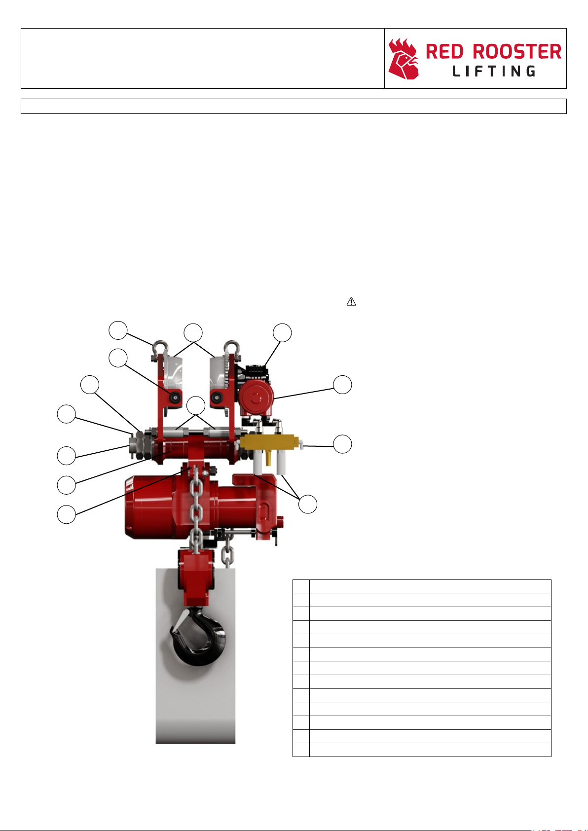
HOSE SUPPORT BRACKET:
Whereahosesupportbracketandmanifoldhavebeenttedtothehoisttotaketheweightofanairsupplyhose,severalchecksmustbedone.
▪ Checkthehosehangsfreelyanddoesnotinterferewiththehoistchain.
▪ Checkthehoseisclearoftheloadtobelifted.
▪ Checkthependanthoseisnotobstructedbytheairsupplyhose.
▪ Checktheairhoseissupportedbythehoseclamp/former/festoonsystem.
▪ DOuseexclusivelycorrectlyratedandcertiedpneumatichosesandttingsintheairsupplyline.
▪ DOsupporttheairlineuptothehoist,asthettingandlter/lubricatorarenotdesignedtotakealoadandmaynotsupportthe
weight of the hose.
▪ DOmaintaintheinternaldiameter(asperthetablethroughoutthesupplylength)orreducefromthelargerdiametertothe
smaller diameter in the direction of the hoist.
▪ DON’Tusehydraulicttings.Theseoftenhaveareducedoricesizeresultinginadownlinedropinairpressure.
▪ DON’Tincreasefromsmallertolargerdiameterorinsertalengthofsmallerdiameterhoseinthesupplylineasthiswillresultin
reducedowandpressure.
▪ DON’Tcreatelowpointsintheairsupplylinewherewatermaybetrapped(orifunavoidableinstalladraintap).
▪ DON’Trelyonpneumaticttingstosupportairlines;theyarenotdesignedforthispurpose.
▪ DON’Tshortenthependantbyformingalooporacoil.Thiswillpreventthestrainerwirefromsupportingthependantandwill
cause the hoses to become detached or kinked.
CAUTIONCAUTION
CAUTIONCAUTION
DANGER

8
USER MANUAL
▪ Red Rooster Lifting Limited ▪Nauta House, The Meadows, Oldmeldrum, Aberdeenshire, AB51 0EZ ▪Tel: +44 (0) 1651 872101 ▪M01-AH12-AT REV1
GETTING STARTED - INSTALLATION & TECHNICAL CHARACTERISTICS
1.4 HOIST ASSEMBLY
Normallyourhoistorhoistandtrolleyswillarrivecompletereadytobettedintoposition,butsometimesfortransportationitmaybe
necessary to disconnect the chain collector, trolley or the pendant control system.
▪ Chaincollectorswillbesuppliedwiththenecessaryboltsandttingstoassembleonsitealongwithanysafetyslingsasshownin
section 1.8 and chain collectors in section 7.4.
▪ Duetothesizeofsometrolleysitiseasiertoshipsplitfromthehoist,thetrolleyGAdrawingsshowtheloadbarandtopeyedetails
forrettingandthecontrolandsupplyairlinesarenumberedorcolourcodedforre-connection.
▪ Whenliftingintopositioneitherusetheliftingpointsonthehoistorhoistandtrolley,ifthehoistdoesnothaveliftingpointsfitted
securely fit slings to the body of the hoist or use the top hook if possible. Do not lift by the controls, valves, or the air set.
MOUNTING THE HOIST
The air hoist is designed as a LIFTING MACHINE and as such is designed exclusively for the lifting loads vertically. Non vertical lifting will
result in premature wear of the chain and chain guide and may result in damage to the limit arms or a failure of the limit arms to operate.
Thetrolleyisdesignedtomoveloadsalongarunwaybeamorswingjib.Itmustbecorrectlyadjustedfortheangewidthandthickness.
▪ Sitethehoistimmediatelyabovetheloadwhichistobelifted.
▪ Ensurethatthepointfromwhichthehoistissuspendedhasbeendesignedandtestedtoatleastthesamesafeworkingloadas
the hoist itself.
▪ Ensurethatthesuspensionpointorshackletssnuglyintothebowlofthehoisttophookandthatthesafetycatchclosesto
prevent escape.
▪ UseonlycertiedliftinggearwithaSWLinexcessoftheloadtobeliftedtoconnecttotheloaditself.
▪ Ensurethattheliftinggeartssnuglyintothebowlofthehoistbottomhookandthatthesafetycatchclosestopreventescape.
▪ Ensurethatthecontrollength(pendantorcords)isadequatetoallowtheoperatortostandawayfromtheload,inasafeand
secure position with the cords or pendant at waist height.
TROLLEY ASSEMBLY
▪ Thoroughlyexaminetheequipmentpriortoinstallationtoensurethatnodamagehasoccurredduringtransit,.
▪ Checkthewheelprofilematchesthebeam.
▪ Neveruseadamagedtrolley.
▪ MatchthetrolleytotheSWLofthebeamandthetypeofhoisttobefitted.
▪ Checktheloadbarnutsaretightandthelinkplateinthecentreoftheloadbar.
▪ Trolleysshouldbecleanedinadrycleanarea.
▪ Donotsideloadthetrolley.
TROLLEY CHECKS
The contents of this section are designed for the guidance of personnel using push or geared trolleys.
▪ Ensurethatthetrolleyissettothecorrectsizeforthebeam.
▪ Ensuretherunwayisfittedwithadequateendstops.
▪ Ensuretherunwayloadpathisclearofobstructions.
▪ Ensurethatthetrolleytiebarsarecorrectlysecured.
DANGER

9
USER MANUAL
▪ Red Rooster Lifting Limited ▪Nauta House, The Meadows, Oldmeldrum, Aberdeenshire, AB51 0EZ ▪Tel: +44 (0) 1651 872101 ▪
M01-AH12-AT REV1
GETTING STARTED - INSTALLATION & TECHNICAL CHARACTERISTICS
1.4 CLOSE HEADROOM WORKING
The lower hook of the TCR / TCS / TMH hoist includes a swivel arrangement. This allows the load to turn without twisting the chain.
However, when repeatedly handling loads with the bottom hook close to the hoist, especially when rotation of the load is prevented, there is
tendency for the chain to attempt to enter the guide at an angle. This is particularly pronounced on two fall units. If this problem is noticed when
doing a trial lift, a high quality ball bearing swivel should be mounted below the bottom hook of the hoist.
CHAIN COLLECTORS
If the hoist has been supplied with a chain collector bag or bucket, and the chain has been stored within it during shipment, remove all the
chain from the collector by hand, and remove any knots or twists.
Inallcasescarefullyfeedthechainovertheloadwheelallowingittollthecollectorwithoutanyinterferenceasitemergesfromthewheel.
Thiswaythecollectorwillllnormally.Ifthechainwithinthecollectorisdisturbedgreatcaremustbetakenthenexttimethatthechainisfed
outofthecollectortoensurethatitisnottwistedorknotted.Chainbagsandbucketsarettedwithoneortwobracketsdependingonthe
model and HOL of the hoist. See additional instructions (Section 6) for large collectors.
1.5 TECHNICAL CHARACTERISTICS
TheWLLofthehoistandtrolleywillbemarkedonthehoist/trolleynameplateandalsointhehoistspecicationsupplied.
The reactions on the powered hoist on the support, runway beam or crane should have been taken into account in the design of the structure.
The structure should be at least 25% stronger than when using manual equipment due to the shock loading applied by the operational speeds
and the starting and stopping of the hoist.
AllRedRoosterhoistsarettedwiththefollowingsafetyfeatures
▪ Overloadlimiter
▪ Upperandlowermechanicallyoperatedtravellimits.Theseareultimatestopsandshouldnotbeusedtostopthehoistonaregular
basis.
▪ Thediscbrakeisspringappliedsowhenthecontrolsarenotoperatedorintheeventoflossofairsupplythebrakeisapplied
holding the load in position.
▪ Onpendantcontrolledhoistsanemergencystopbuttonisfittedwhichconnectstoanormallyopenvalveeitherlocatedinthehoist
valve chamber or connected to the hoist. When the emergency stop button is pushed or if the air supply to the hoist is cut off then
the valve will close stopping the hoist.
▪ RedRoosterhoistshavea5:1factorofsafety.
DANGER

10
USER MANUAL
▪ Red Rooster Lifting Limited ▪Nauta House, The Meadows, Oldmeldrum, Aberdeenshire, AB51 0EZ ▪Tel: +44 (0) 1651 872101 ▪M01-AH12-AT REV1
GETTING STARTED - HOIST CHECKS
1.6 HOIST CHECKS BEFORE USE
HOIST CHECKS (AIR SUPPLY OFF)
▪ Hookswivelssatisfactorilyandthesafetycatchesworkcorrectly.
▪ Loadchainisundamagedandlubricated(lightmineraloil).
▪ Theloadchainisnottwistedthrough(twofallormoremodels)andthattheloadchainpassedthroughthelimitlever(Allmodels).
▪ Theloadchainanchorissound(bothliveandslackend).
▪ Checkfordamagetothehoist,pendantandcontrollines.
▪ Donotoperatedbelow-10°C or above 70°C without contacting Red Rooster. (The hoist can be used down to -20ºC with small
modications)
HOIST CHECKS (AIR SUPPLY ON)
▪ Thependantbuttons,leversorcordsshouldbesmoothtooperateandreturntoneutralwhenreleased(hoiststopsanddoesnot
run on).
▪ Thehoistisrunupanddownonaregularbasis.Wherehoistsarehanginginadryandprotectedareatheyshouldberunweekly,
where the hoist is outside and not protected it should be checked, lubricated and run daily.
▪ Theemergencystopbutton/valveoperatesimmediately.
▪ Upperandlowerlimitswitches/leversworksatisfactorily.
▪ Loadchainsrunsmoothlyoverthepocketwheel.
▪ Theloadchainshouldbeexaminedperiodicallyforcracks,gougesandwear.
▪ Chaincollectorsshouldbecheckedforsecurityandchaincapacity.
▪ Checkchainrunsinandoutofthechaincollectorsmoothly.
▪ Forhoistswithalongdropofchainoralargechaincollectoraseparatesuspensionpointmayberequired(seesection1.8).
▪ Cordcontrolhoistsshouldhavethetogglesmarkedforraiseandlower.
▪ Oncordcontrolscheckthespoolvalvereturnstoneutralandthehoiststopswhenthecordisreleased.(hoiststopsanddoesnot
run on).
▪ Checkthesilencerisnotpartiallyblockedbycomparingtherunningspeedwithoutloadagainstthespeedinthemanual.
NEVER RELEASE THE EMERGENCY STOP BUTTON UNTIL IT IS SAFE TO DO SO
Hoist swivels satisfactorily.
Hoist safety claws functional and undamaged.
Safety claw
Chain undamaged
Chain not twisted through (two fall models see sketch)
twisted
DANGER
DANGER
correct
DANGER

11
USER MANUAL
▪ Red Rooster Lifting Limited ▪Nauta House, The Meadows, Oldmeldrum, Aberdeenshire, AB51 0EZ ▪Tel: +44 (0) 1651 872101 ▪
M01-AH12-AT REV1
GETTING STARTED - HOIST CHECKS & INSTALLATION INSTRUCTIONS
1.7 HOIST CONTROLS
Air hoists can be controlled by either a pull cord or a pendant control operating the spool valve of the hoist operating raise and lower. The
diagram at the bottom of this page shows the set up for both types of control and the location on the hoist body.
Cord or pendant hose lengths should be long enough for the operator to stand away from under the load but still with the cord toggles or the
pendant suspended at a height of around 1 metre from the operating level. Where the controls have to be to the side of the hoist or
where the operator cannot see the load travelling the full range of the lift a banksman should be appointed to assist the operator using a
reliable means of communication.
1.8 ADDITIONAL INSTALLATION INSTRUCTIONS
Hook suspension with long chain drops.
Problem:
Whenalongheavychainistted,andthe‘raise’ispressedwiththehoistinanunloadedcondition,duetothecentrelineofthehoisthaving
beenaectedbytheweightofchain,theupperlimitswitch,mayfailtooperate.Inaddition,theslackloadchainmayonsomemodulesfoul
the limit lever arms, thus preventing it from returning to the centre (neutral position).
Resolution:
Ashortlengthofwirerope,6mmdiameter,isttedtothehoistsandbulldoggripshavebeensupplied.
Suspendthehoistinitsnallocationandwithasmuchchainaspossibleinuse.Applyasmallloadtothehoistandliftitclearoftheground.
Connect the wire rope sling to the support steel alongside the top hook using bulldog grips.
The tension in this sling should be enough to counteract most of the weight of the slack chain produced in the fully raised position, but it must
notbetensionedsuchthatitiscarryinganyoftheloadsupportedbythehoist.i.e.ifttedcorrectly,inanunloadedcondition,theslingwillbe
tensioned with the hoist ALMOST in the vertical position. When the load is applied, the tension in the sling will be slack.
Trolley Resolution:
Whenahoistandtrolleyarettedwithheavychainoralongdrop,asecondpushtrolleycanbeusedinthesamewaytosupporttheweight.
THE SLING IS NOT CAPABLE OF HOLDING THE LOADS CARRIED BY THE HOIST

12
USER MANUAL
▪ Red Rooster Lifting Limited ▪Nauta House, The Meadows, Oldmeldrum, Aberdeenshire, AB51 0EZ ▪Tel: +44 (0) 1651 872101 ▪M01-AH12-AT REV1
GETTING STARTED
STANDARD HOSE CONNECTION
PENDANT CONTROL OR
HOIST WITH EXTERNAL
EMERGENCY STOP VALVE
STANDARD HOSE CONNECTION
CORD CONTROL OR
HOIST WITH INTERNAL
EMERGENCY STOP VALVE

13
USER MANUAL
▪ Red Rooster Lifting Limited ▪Nauta House, The Meadows, Oldmeldrum, Aberdeenshire, AB51 0EZ ▪Tel: +44 (0) 1651 872101 ▪
M01-AH12-AT REV1
GETTING STARTED
*
*Somehoistsarettedwithinternalemergencystopvalves
**Thehoseclampcanalsobettedtothetrolleysideplate.

14
USER MANUAL
▪ Red Rooster Lifting Limited ▪Nauta House, The Meadows, Oldmeldrum, Aberdeenshire, AB51 0EZ ▪Tel: +44 (0) 1651 872101 ▪M01-AH12-AT REV1
GETTING STARTED - INSTALLING THE HOIST & TROLLEY
1.9 RRL trolleys can be plain (non-powered), hand chain (geared) or powered (pneumatic) Hoists can be hook-mounted to the suspension shaft of the
trolley, or rigidly mounted to a trolley hanger bracket.
This trolley has been designed for horizontally transporting loads by hand, through manual or pneumatic hoists under normal atmospheric
conditions of the work place.
In order to ensure the maximum performance and life from this pneumatic trolley it is essential that the following points are strictly observed.
▪ Thetrolleyairmotormaybeoperatedinanyattitudeprovidedadequatelubricationissupplied.
Being totally enclosed they can be used in any environment within the temperature limits of -10ºC to +50ºC.
(optional parts -20ºC to +60ºC)
▪ Themaximumworkingpressurefortheairmotoris7bar(100psi)
▪ Besuretoadjusttheanti-tiltrollerstothehighestpositionpossibleintheslottoleavetheminimumclearancebetweentheunderside
of the beam and the top of the roller.
▪ Axialloadsshouldbekepttoaminimum.
▪ Careshouldbetakenwhenfittingdrivecomponentstotheshaft,thatexcessiveforceisnot used.
This will upset the rotor alignment which has been kept to a minimum in order to give high motor performance.
▪ Checkthedrivepinion/gearedwheelsaregreased.
OPERATION
Plain Trolley The trolley movement is controlled by pushing the load or the hook of the attached hoist.
Geared Trolley Face the hand wheel side of the trolley.
To move left, pull hand chain clockwise.
To move right, pull hand chain counterclockwise,
Pneumatic Trolley The trolley direction is controlled by the pendant buttons or levers.
Face the trolley motor side plate and use the white or black arrows to control the pendant.
The emergency stop buttons stops the trolley.
Trolleys are either delivered assembled for the beam size advised, or assembling but require to be adjusted to the correct beam size.
The lifting points at the top of the trolley above the gearbox should be used for lifting the hoist and trolley into place. Care must be taken not to
allow the unit to swing, as the gearbox flange can be damaged and broken if it is allowed to impact against steelwork etc. If contact is made, the
flange should be inspected and removed from service for repair.
MOUNTING
Make certain the hoist is properly installed. A little extra time and effort in doing so can contribute a lot toward preventing accidents or injuries and
will help achieve the best service possible.
When installing a trolley on a beam, measure the beam flange width and temporarily install the trolley to determine the exact distribution and
arrangement of the spacers.
HOOK MOUNTED HOIST
After final trolley installation place hook over suspension shaft or eye. Make sure hook latch is engaged.
If the hoist is suspended by a top hook, the trolley suspension shaft should rest completely within the saddle of the hook and be centred directly
between the side plates.
RIGID / EYE MOUNTED HOIST
Mount hoist to trolley and temporarily install on beam to determine exact distribution of spacers to centre the top eye.
After installation, operate trolley over entire length of beam with a capacity load suspended 10 to 15cm off the floor.

15
USER MANUAL
▪ Red Rooster Lifting Limited ▪Nauta House, The Meadows, Oldmeldrum, Aberdeenshire, AB51 0EZ ▪Tel: +44 (0) 1651 872101 ▪
M01-AH12-AT REV1
GETTING STARTED - INSTALLING THE HOIST & TROLLEY
1.9 FITTING TROLLEYS IN LOCATION
MOUNTING FROM THE RAIL END
Air trolleys can either be fitted to the runway beam or swing jib in two ways.
1) By removing the end stop from the beam and sliding the trolley which is already set for the flange size on to the beam and then re-fitting
the end stop.
MOUNTING BY DISASSEMBLING THE MAIN TROLLEY BODY
2) By opening the trolley up so that the inner part of the wheels will pass over the beam flange and then sliding the trolley side plates back
along the shaft, refitting the spacers, washers and nuts and then tighten up the nuts and check the wheel setting. Be sure to firmly
support the parts during reassembly from the bottom side so that the side-plates are not twisted or otherwise shifted. On completion of
reassembly, be sure to confirm that various shafts, nuts, lock pins and split pins are properly fastened without any slack and have not
been loosened.
END STOP
PLAIN SIDE PLATE
ASSEMBLY
MOTOR SIDE PLATE
ASSEMBLY

16
USER MANUAL
▪ Red Rooster Lifting Limited ▪Nauta House, The Meadows, Oldmeldrum, Aberdeenshire, AB51 0EZ ▪Tel: +44 (0) 1651 872101 ▪M01-AH12-AT REV1
GETTING STARTED - INSTALLING THE HOIST & TROLLEY
1.9
SETTING THE TROLLEY (up to 3 tonne)
1) Slide the hook receiving part or link plate near the suspended shaft centre and grease the shaft.
2) Distribute the spacer rings and adjusting collars equally to either side of the link plate, in order to obtain the dimensions between the
wheels, corresponding to the beam width plus 2 or 3mm.
3) Distribute on each side of the side plates, washers and adjusting collars that are remaining and screw a nut on each extremity.
4) Tighten the nuts and lock nuts on the load bar and check the clearance between the beam flange and the
wheel flange.
5) Position the tie-rods, anti-tilt rollers, washers and nuts into the slots in each of the side plates. Set to give the minimum amount of
clearance between the underside of the beam and the top of the anti-tilt roller. Then tighten the nut against the roller and side plate and
re-check the wheel setting.
PLAIN
SIDE-PLATE
MOTOR
SIDE-PLATE
WHEELS
ANTI-TILT
ROLLERS
TIE
BAR
LOAD
BAR
SPACER
WASHERS
SPACERS
BUFFERS

17
USER MANUAL
▪ Red Rooster Lifting Limited ▪Nauta House, The Meadows, Oldmeldrum, Aberdeenshire, AB51 0EZ ▪Tel: +44 (0) 1651 872101 ▪
M01-AH12-AT REV1
GETTING STARTED - INSTALLING THE HOIST & TROLLEY
1.9
TROLLEY CHECKS
▪ Ensuretherunwaybeamisfittedwithadequateendstopswhichstrikethebuffer/anti-dropplateonthetrolley.
▪ Ensuretherunwayloadpathisclearofobstructions,flatandingoodcondition.
▪ Ensuretheteethfromthepinionfitcorrectlyintotherackonthebeam(iffitted)
▪ Theairsupplyhoseshouldnotbesuspendedfromthehoistwithoutsupport.Wherefeasible,atautwireorafestoon
system should be fitted to allow the hose to run along the beam, without loading the air set or fittings.
▪ Thehoistconnectionplateshouldbeinthecentreoftheloadbarwithanequalamountofspacerseachside.
▪ Whenatrolleyhasbeenopened/splitforadjustingorfitting,theloadbarandtiebarnutshouldbere-tightened.
▪ Thetrolleysideplatesshouldbeparalleltothebeamflangewhenthenutsaretight.
▪ Donotusethebeamendstopstostopthetrolleyonaregularbasis.Itisasafetymeasure.
DO use exclusively correctly rated pneumatic hoses and fittings in the air supply line.
DO maintain the internal diameter (as per the table throughout the supply length) or reduce from the larger diameter to the smaller
diameter in the direction of the hoist.
DO support the airline up to the hoist, as the fittings and filter/lubricator are not designed to take a load and may not support the
weight of the hose.
DON'T use hydraulic fittings as these tend to have a reduced orifice size resulting in a down line drop in air pressure.
DON'T increase from smaller to larger diameter or insert a length of smaller diameter hose in the supply line as this will result in
reduced flow and pressure.
DON'T create low points in the air supply line where water may be trapped (or if unavoidable install a drain tap)
DON'T shorten the pendant by forming a loop or coil. This will prevent the strainer wire from supporting the
pendant and will cause the hoses to become detached or kinked.
DON'T allow the air hose to hang from the air set. Neither the air set or fittings are designed to take the weight of the hose.
OPERATION - LOW HEADROOM & ULTRA LOW HEADROOM TROLLEY
1.9 ▪ TheLHRandULHRtrolleyshouldonlybeusedonstraightrunwaybeams.Specialunitsareavailableforcurvedbeamsdesignedto
suit the radius.
▪ LHRandULHRtrolleysareusuallydesignedforasetbeamsizebutcanbemadeadjustableifrequired.
▪ LHRandULHRunitsareavailableasstandardorUKEx/ATEXversionsandwithourin-housedesignteamspecialunitscanbe
manufactured to suit your requirements.
▪ LHRunitsarealsoavailableasarticulatedunitsorwithrackandpiniondriveorbeambrake.
DANGER CAUTION
DANGER
A
-
A
C ( 1:1.5 )
A
A
PARTS LIST
REV.
DESCRIPTION
PART NUMBERQTYITEM
0Buffer 41
Hexagon Socket Head Cap ScrewANSI B18.3 - 1/4 - 20 UNC - 3/4 HS HCS
32
WasherDIN 125 - A 3143
WasherDIN 125 - A 6.444
Spring Retaining RingDIN 471 - 25 x 1.245
Retaining rings for shaftDIN 471 - 35x1.5
26
Spring Retaining RingDIN 472 - 52 x 247
Spring Retaining RingDIN 472 - 62 x 228
Deep groove ball bearings single row with two Z shields SKFDIN 625 SKF - SKF 6007-2Z
2
9
Deep groove ball bearings single row with two Z shields SKFDIN 625 SKF - SKF 6205-2Z410
Parallel KeyDIN 6885 - A 6 x 6 x 36211
Parallel Key
DIN 6885 - A 6 x 6 x 40212
Parallel KeyDIN 6885 - A 6 x 6 x 70113
Cylinder Head Cap ScrewDIN 7984 - M8 x 25114
Washer
DIN 9021 - 8.4
115
Cylinder Head Cap ScrewDIN 912 - M6 x 201216
Cylinder Head Cap ScrewDIN 912 - M6 x 35417
Hexagon Socket Set Screw
DIN 913 - M5 x 8218
Hexagon Socket Set ScrewDIN 913 - M8 x 30419
0
Transition Piece (for NORD Gearbox)
DRG 1225-02
1
20
0SpacerDRG 1500-09
depends on
the Flange
21
0Spacer WasherDRG 1500-10
depends on
the Flange
22
0Gear WheelDRG 1500-11223
0Plain Wheel
DRG 1500-12224
0Tie RodDRG 1500-13225
0Anti Tip RollerDRG 1500-14426
0
0
0
Load Bar (Range I - Flange 55÷140mm)
Load Bar (Range II - Flange 140÷220mm)
Load Bar (Range III - Flange 220÷300mm)
DRG 1500-15 or
DRG 1500-16 or
DRG 1500-17
227
0
Pinion Shaft (for NORD Gearbox)
DRG 1500-37128
0
Side Plate Left
DRG 1525-03129
0Side Plate RightDRG 1525-04130
0
Transfer Gearwheel HolderDRG 1525-112
31
0Transfer ShaftDRG 1525-13132
0Transfer GearwheelDRG 1525-14233
Split PinISO 1234 - 4 x 40
434
Hex NutISO 4032 - M10835
Hex NutISO 4032 - M6436
Hex Nut
ISO 4032 - M8
437
Hex NutISO 4035 - M30838
0
1/4'' NordLock Washer Large Diameter Glued PairNL1-4in
3
39
0M10 NordLock Washer Large Diameter Glued PairNL10sp840
0M6 NordLock Washer Large Diameter Glued PairNL6sp1241
0M8 NordLock Washer Large Diameter Glued PairNL8sp442
0
Gearbox (ratio 15:1)
SK 1SI40FH-IEC63-2G
143
0Air MotorVA4J144
C
Title of Project
Approved By
Checked By
Drawn By
Designed By
B. Aitken
T. Mikolajewski
E. Crichton
1:3.5
Scale
Surname
Surface Roughness
Angular
`
0,5°
Linear
If In Doubt Ask
1 / 1
35.4 kg
Weight
0
Title of Part
2TE LOW HEADROOM
Date
Material
Sheet Size
A3
TROLLEY
Date
Revision
Profile Number
Replaces Drawing
13/02/2018
Signature
Part Number
DRG 1525D-01
up to 5
`
0,05
over 5 up to 30
`
0,1
over 30 up to 120
`
0,2
over 120 up to 500
`
0,25
over 500 up to 1000
`
0,5
over 1000
`
1
N10
Tolerances
all dimensions are in milimeters
unless otherwise specified
04/04/2014
13/02/2018
REVISION HISTORY
REV. DATE APPROVED
017/04/2018 W. Morrison
43 20 44
510
19
37
42
43
3032 2221
38
27
34
570
520
260
240
12
23
33
73026
25 35 40 339
6
293184116
18
1
17 36 4
28
2
39
311
13 1415
24
23

18
USER MANUAL
▪ Red Rooster Lifting Limited ▪Nauta House, The Meadows, Oldmeldrum, Aberdeenshire, AB51 0EZ ▪Tel: +44 (0) 1651 872101 ▪M01-AH12-AT REV1
ASSEMBLY AND INSTALLATION - RACK & PINION TROLLEY
1.10 ▪ Thefittingofarackandpiniontrolleysisverysimilartoastandardairtrolleywiththeadditionofthepinion
adjustment to mesh with the rack on the runway beam or swing jib.
▪ Thefourboltsonthedrivenandnon-drivenadjustingplatesshouldbeslackenedtoallowtheplatestodrop
down to the maximum rack clearance.
▪ Fitthetrolleyontothebeamasperthestandardinstructions.
▪ Pushtheadjustingplatesupsothatthepinionmesheswiththerackonthebeam,thelowerdownby1to1.5mm.
▪ Slightlytightenthefourboltsonbothadjustingplates.
▪ Checkthepinionshaftisparallelwiththebeamflangeandadjustifnecessary.
▪ Tightenuptheeightbolts
▪ Checktheclearancehasnotchangedbetweenthepinionandtherack.
▪ Functiontestwithaload.
▪ Re-checkthesecurityofallnutsandboltsonthetrolley.
ASSEMBLY AND INSTALLATION - BEAM BRAKE TROLLEY
(See standard trolley installation instructions)
Air and geared trolleys fitted with a beam brakes are manufactured to fit only the size of beam flange they are designed for. If they
have to be moved to another beam then a new beam brake shaft would be required.
Trolleys can either be air powered or gear travel and are based on a standard trolley fitted with blocks or pads to lock the trolley in location when
the chain wheel is turned. The chain is then turned the other way to release the trolley.
Fitting of a trolley with a beam brake should be done from the end of the beam with the end stops removed for fitting. It can be difficult to open up
the trolley to fit over the beam and then close up again while suspended.
Check operation of beam brake when locked in position. Close beam brake and then try pulling the geared drive chain checking that the trolley
does not move.
Title of project Material Weight
Checked by
Designed by
Approved by
Scale Title of part Part number
Revision number
Replaces draw
Surname
Date
Signature
1TE Rack & Pinion Hoist 26/02/2014 -40kg
Date
-
0
1:2,5 Trolley (HEB 200 / 3.0 modeule) DRG 1518-28 no dim.
T. Mikolajewski
S. Przygoda
B. Aitken
red rooster
Red Rooster Industrial (UK) Ltd,
Nauta House, The Meadows,
Oldmeldrum, Aberdeenshire, AB51 0EZ
Tel: +44(0)1651 872101
Main Fax: +44(0)1651 872098
Sales Fax: +44(0)1651 871405
www.rriuk.com
sheet 1/2

19
USER MANUAL
▪ Red Rooster Lifting Limited ▪Nauta House, The Meadows, Oldmeldrum, Aberdeenshire, AB51 0EZ ▪Tel: +44 (0) 1651 872101 ▪
M01-AH12-AT REV1
ASSEMBLY AND INSTALLATION - LHR, ULHR & ARTICULATED TROLLEY
1.10 ▪ Thefittingofanarticulatedtrolleywilldependonthedesignofthepowertransferbetweenthetrolleydrivewheels.Thiscaneitherbe
with a motor gearbox at one side with a transfer shaft across to the geared wheel on the plain side plate or the trolley can have a motor
gearbox on both side plates to drive the trolley.
▪ Thefittingofthetrolleyontothebeamcaneitherbefromtheendofthebeamorthetrolleycanbeopeneduptofitoverthebeam
flange.
MOUNTING FROM THE END OF THE RUNWAY BEAM
▪ Checkthetrolleywheelsettingagainsttherunwaybeamflangesize(thesettingshouldbeasperthestandardtrolleysetting)
▪ Removetherunwaybeamendstopandslidetheassembledtrolleyontotherunwaybeampastthepositionfortheendstopandthen
re-fit the end stop
▪ Checkthewheelsettingandconnecttheairsupplythenfunctioncheckthetrolleywithoutloadalongthestraightandcurvedsectionsof
the runway beam.
▪ IfthetrolleyrunsalongtheworkingareawithoutproblemlifttheSWLforthehoistandtrolleyandtravelalongtherunwaybeam
checking for any problems travelling around the curves and over joints.
MOUNTING BY DISMANTLING THE MAIN TROLLEY BODY (TRANSFER SHAFT) - CAUTION
▪ Ifthetrolleyisfittedwithatransfershaftandtheloadbarsaremadeforasetsize,severalpartssuchasthetransfershaft,gears,
and bolts will have to be removed at ground level when opening the trolley and then refitted when the trolley side plates are positioned
at either side of the runway beam.
▪ Positiononeortwohoistsateithersideoftherunwaybeam,connectthebottomhookstheliftingpointsonthetrolleysideplatesandlift
the trolley side plates up to a position where the trolley wheels are level with the beam flange.
▪ Whileholdingthetransfershaftandloadbarsinpositionclosetheplainsideplateontothebeamliningupthetransfershaftgearsand
load bars. Check the security of the shafts, load bars and tie bars.
▪ Carryoutchecksandfunctiontestsasperitem1
MOUNTING BY DISMANTLING THE MAIN TROLLEY BODY (DUAL MOTORS)
▪ Wheredualairmotoraremountedontwotrolleysideplatesthisallowsforthetrolleystobeeasilyopenedupatgroundlevel,liftedup
and then closed on to the beam flange.
▪ Checktrolleyflangesettingmatchestherunwaybeamflange
▪ Positionthehoistandtrolleyunderthebeamwherethehoistsistobeinstalled
▪ Positiontwoorfourhoistsabovetherunwaybeamandconnectthebottomhookstotheliftingpointsonthetrolleysideplates.
▪ Slackentheloadbarandtiebarnutssothatthesideplatescanslideapart,thenchecktheopeningbetweentheinsideofwheelsis
wide enough to go past the beam flange.
▪ Keepingthetrolleylevelliftthetrolleywheelsuptothelevelofthebeamflange.
▪ Nextpushthetrolleysideplatestogether,thentightenthenutsontheloadbarandtiebars,checkallpartsaresecure.
▪ Checkthetrolleywheelsettingonthebeam(asperstandardtrolley)andthenconnecttheairsupplyandfunctiontestthetrolleywithout
load along the full length of the curved and straight sections of the runway beam.
▪ NextwiththeSWLofthehoistandtrolleyrunthetrolleyalongtherunwaybeamcheckingmovementaroundanycurvedsectionsand
over joints.
Title of project Material Weight
Checked by
Designed by
Approved by
Scale Title of part Part number
Revision number
Replaces draw
Surname
Date
Signature
Articulated beam trolley SWL 6T 2011-04-26 -202kg
Date
-
0
1:5 Assembly DRG 1473-00
T. Mikolajewski
S. Przygoda
B. Aitken
red rooster
Red Rooster Industrial (UK) Ltd,
Nauta House, The Meadows,
Oldmeldrum, Aberdeenshire, AB51 0EZ
Tel: +44(0)1651 872101
Main Fax: +44(0)1651 872098
Sales Fax: +44(0)1651 871405
www.rriuk.com

20
USER MANUAL
▪ Red Rooster Lifting Limited ▪Nauta House, The Meadows, Oldmeldrum, Aberdeenshire, AB51 0EZ ▪Tel: +44 (0) 1651 872101 ▪M01-AH12-AT REV1
LUBRICATION
2.1
Note 1
In all cases oil will be expelled from the hoist and trolley exhaust. The amount discharged is proportional to the delivery rate of the lubricator.
In environments where oil in the exhaust cannot be tolerated, the exhaust can be piped away to a safe area, but this requires specialist
modicationofthehoist(Seeairserviceequipment)-CONSULTYOURDEALER.
Note 2
All Red Rooster hoist chain must be lubricated to prevent wear.
Keeping load chain clean and lubricated will greatly increase the lifetime of the chain and prevent costly replacement. Very little lubricant is
needed and can be easily applied to the chain by cloth, brush or spray.
Note 3
Geared wheels (air + geared trolley only) - Lubricate exposed trolley drive pinion and wheel teeth. Brush with grease as often as necessary to
keep teeth liberally covered. If the grease becomes contaminated with sand, dirt or other worn materials, remove old greases and replace with
new grease (standard grease) during monthly or annual inspection. Temperature range of standard grease is -10ºC to +50ºC. If the trolley is used
at temperature below -10ºC or above +50ºC, consult Red Rooster since come parts shall be changed.
Note 4
Trolley wheel bearings do not need to be lubricated and must be replaced if worn or damaged. Hand chain, used on geared trolleys, does not
normally require lubrication.
In areas of high corrosion, plated chain can be used along with special lubricants to prevent corrosion from sea water and spray. Chains used
in these areas should be re-lubricated on a regular basis.
NEVER use heavy grease or bitumen based products to lubricate the chain as these will foul the chain guide, idler and load wheels and
bearings.
RemovedustandwaterdropsontheLoadChainandthenapplylubricant.ApplicationoflubricationinuencesonthelifeoftheLoad
Chainconsiderably.Applythelubricantsuciently.
AIR SUPPLY FILTER, REGULATOR AND LUBRICATOR LOAD CHAIN LUBRICATION
Item Oil Type Frequency
Lubricator Unit
Main Air Supply
Atlub
Medium to light turbine oil
ISO VG 32-56
Or any quality airline lubricant
(See note 1)
10 to 15 drops per minute
Do not allow lubricator to run out of oil
Load Chain Normal industrial - any light mineral oil
Clean areas - wax based, semi setting
Food industry - suitable vegetable oil
(See note 2)
Weekly / monthly subject to environment / use
Limit Lever Linkages
and Anchor pins
No. 2 grease Monthly or more frequently in aggressive
environments
Gearbox (Hoist) High temperature EP2 grease Only at major overhaul
Gearbox (Trolley) Grade VG220 Only at major overhaul
Trolley Drive Pinion No. 2 Grease Monthly or more frequently in aggressive
environments
DANGER
CAUTIONCAUTION
DANGER
Applied
Position
Load
Filter Regulator Lubricator
Air In Air Out
Table of contents
Other RED ROOSTER Chain Hoist manuals

RED ROOSTER
RED ROOSTER TCS-500-AT2S-LF User manual

RED ROOSTER
RED ROOSTER TCS-500-LF User manual

RED ROOSTER
RED ROOSTER TMH-3000 User manual

RED ROOSTER
RED ROOSTER TMH-3000-LF User manual

RED ROOSTER
RED ROOSTER TMH-30T-CH User manual

RED ROOSTER
RED ROOSTER TCS-980-AT2S User manual

RED ROOSTER
RED ROOSTER TMH-3000-CH User manual

RED ROOSTER
RED ROOSTER TCR-1000-CH User manual

RED ROOSTER
RED ROOSTER TMH-25T-CH User manual

RED ROOSTER
RED ROOSTER TCR-250 User manual