Red Sea MAX S-Series User manual

EN
Red Sea MAX®S-Series LED
Complete Coral Reef Systems | Installation & Operation Manual


2
MAX®S-Series LED Installation & Operation Manual’s
Index:
Introduction �������������������������������������������������������������������� 3
Safety ������������������������������������������������������������������������������ 4
Location��������������������������������������������������������������������������� 5
Assembly ������������������������������������������������������������������������ 6
Operation ���������������������������������������������������������������������13
Maintenance �����������������������������������������������������������������16
Warranty������������������������������������������������������������������������17

3
MAX®S-Series LED Installation & Operation Manual’s
Introduction
Congratulations on your purchase of the Red Sea MAX®S LED complete reef
system.
Red Sea developed the MAX®to provide a complete reef spec system so that
from the beginning, you can focus on the aquarium’s inhabitants rather than
the hardware.
The Red Sea MAX®approach to the coral reef experience is to create an
environment that is specifically attuned to the need of corals and all reef
inhabitants on an artificial reef. In the ocean coral reefs flourish only where
specific physical conditions prevail, such as sufficient light, adequate current,
stable temperature and water clarity.
The Red Sea MAX®provides a system that creates the conditions that enables
you to keep a thriving, healthy reef in your own home.
This manual contains the installation and operational instructions for all of the
MAX®S aquariums.
We hope that you enjoy your MAX®and wish you happy reefing.
To benefit from product update information and exclusive special offers to
registered MAX®owners, please register your MAX®on-line at redseafish.com
MAX®S-Series LED
Installation & Operation Manual

4
MAX®S-Series LED Installation & Operation Manual’s
Safety
PLEASE READ AND FOLLOW ALL SAFETY INSTRUCTIONS
DANGER: To avoid possible electric shock, special care should be taken when handling a wet aquarium.
For each of the following situations, do not attempt repairs yourself; return the appliance to an authorized
service facility for service or discard the appliance.
WARNING: To guard against injury, basic safety precautions should be observed, including the following:
Do not operate any appliance if it has a damaged cord or plug, if it is malfunctioning, or if it is dropped or
damaged in any manner.
If the external cable Is damaged, It shall be replaced by the manufacturer.
To avoid the possibility of the appliance plug or receptacle getting wet, position the aquarium stand and
tank to one side of a wall mounted receptacle to prevent water from dripping onto the receptacle or
plug. You should create a “drip loop” (see Figure 1) for each cord connecting an aquarium appliance to a
receptacle. The “drip loop” is that part of the cord below the level of the receptacle, or the connector. Use
an extension cord, if necessary, to prevent water traveling along the cord and coming into contact with the
receptacle. If the plug or receptacle does get wet, DO NOT unplug the cord. Disconnect the fuse or circuit
breaker that supplies power to the appliance. Then unplug the device and examine for presence of water in
the receptacle.
Close supervision is necessary when any appliance is used by or near children.
To avoid injury, do not contact moving parts.
Always unplug an appliance from an outlet when not in use, before putting on or
taking off parts, and before cleaning. Never pull the cord itself to remove the plug
from the outlet. Grasp the plug and pull to disconnect.
Do not use an appliance for anything other than its intended use. The use of
attachments not recommended or sold by the appliance manufacturer may cause an
unsafe condition.
Do not install or store the appliance where it will be exposed to the weather or to
temperatures below freezing point.
Make sure an appliance mounted on a tank is securely installed before operating it.
Read and observe all the important notices on the appliance.
NOTE: A cord rated for less amperes or watts than the appliance rating may overheat. Care should be taken
to arrange the cord so that it cannot be tripped over or pulled accidental.
Figure 1: Drip
Loop

5
MAX®S-Series LED Installation & Operation Manual’s
Location
The first step in setting up the MAX®S is to choose a suitable location.
Weight
The MAX®S aquariums are supported by 9-12 adjustable feet (depending on model). The flooring directly
below the legs must be rated for a static loading of at least 15 kg / cm2 (220 lbs/square inch).
Room temperature
Site selection is important for correct temperature maintenance. We recommended that you keep the
ambient room temperature a comfortable and stable 22°C / 72°F. Avoid placing the tank in front of an air
conditioner, heating vents or direct sunlight. A well ventilated room with moderate light is the best place to
position the aquarium.
Accessibility
• Back: Ensure that there is at least 15cm / 6” of clearance behind the MAX®to allow for operation and
maintenance of the flow valve on the main downpipe as well as sufficient air circulation for a chiller.
• Sides – Rear: Ensure that there is sufficient room (approximately 60cm / 24”) between both sides
of the aquarium and any adjacent walls or furniture for access to the rear of the tank. In addition to
the regular maintenance of the surface skimmer, pumps and return flow vents of the rear chamber,
specific access is required as follows: Left side - filling of Top-up water reservoir, installing/removing
cables to power drawer. Right side – adjustment and maintenance of down-flow valve.
• Sides – Front: Ensure that there is approximately the length of the tank free on at least one of the
sides. This is to enable the installation/replacement of the color trim on the tank as well as being able
to replace the tubes in the front and rear light units without having to remove it from the aquarium.
General considerations:
Ensure that the area surrounding the aquarium is waterproof and consider moving away anything that water
might damage or may be corroded by the salt.
NOTE: The MAX®S system should not be moved when full of water.

6
MAX®S-Series LED Installation & Operation Manual’s
Assembly
Detailed instructions for the complete assembly of the MAX®S can be found in the accompanying graphic manual.
It is important to assemble the MAX®S in the order indicated. The following information compliments the graphic
manual.
If you are planning on pre-assembling the cabinet before transporting the MAX®S to its final location, complete
only the stages 1 & 2 as per the graphic manual.
NOTE: Left and Right designations are when looking from the front of the Aquarium.
Tools
The assembly requires the following tools:
• Adjustable torque Power Drill/Driver (at least 12V) with a crosshead bit
on a 5cm / 2” extension.
Do not use an impact power driver
• Regular crosshead and flat screwdrivers
• Rubber Mallet
• Spirit level (at least 60cm / 2”)
Components
• The MAX®S system includes the following main components:
• MAX®S type glass aquarium with integral top-up reservoir
• Cabinet (self-assembly)
• MAX®S LED lighting unit
• Power Center
• Glass Sump including micron filter bags, Carbon media and Float valve
for automatic top-up
• Internal Piping
• RSK Protein Skimmer
• Main return pump
• Circulation pumps (number according to model)
Color pack:
• Cabinet sides and doors
• Trim pack for aquarium, cabinet and lights

7
MAX®S-Series LED Installation & Operation Manual’s
Cabinet assembly
WARNING: If you are not experienced in the construction of self assembly furniture, seek suitably qualified
assistance�
The parts of the frame are connected by screwing self-tapping screws through the corner brackets into pre-
drilled holes in the aluminum profiles. This is best achieved by using a power drill with an adjustable torque. It is
necessary to apply pressure when screwing self tapping screws into aluminum. To ensure that all screws of the
frame are properly seated the manual shows turning the frame around during the various stages of assembly so
that pressure can easily be applied by screwing downwards while the parts are supported by the floor.
When screwing into plastic parts such as the aquarium base board or the lower front plinth, use a hand
screwdriver and not the power driver.
NOTE: The upper and lower plinths are part of the color trim pack.
The adjustable feet on the bottom of the cabinet enable the system to be leveled irrespective of the flatness of
the floor. When assembled the height of the feet can be adjusted so that the bottom edge of the side panels will
be 6–12mm (1/4” – ½”) above the floor. Initially assemble the 4 corner feet to the highest position and all other
feet to be touching the stainless steel foot plates.
Placing Aquarium
Before placing the aquarium in its operating position familiarize yourself with top-up reservoir outlet, main pump
and down pipe connections and the flow control valve that are located at the back right corner of the aquarium.
Once the system is in its operating position approximately 15cm (6”) from the wall, the valve and connectors are
accessible from the side.
WARNING: Lifting the glass aquarium onto
the cabinet will require at least 4 people.
The top of the cabinet is approximately
92cm / 36” from the floor. The table
shows the approximate weights of the
different models of MAX®S aquarium.
Ensure that anyone lifting the aquarium is
physically suitable for such an operation
and has been instructed in the correct
methods of lifting heavy objects.
Aquarium must be lifted from the bottom.
Take care not to damage the plastic rim on the front and sides at the top and bottom of the glass. Some damage
to the rim will not affect the assembling of the external color trim.
Before lifting aquarium, place the assembled cabinet in the final operating position (see location above) and set
the glass aquarium in position on top.
The back of the glass should be flush with the rear edge of the cabinet top board. The front and sides of the glass
should protrude slightly beyond the edges of the cabinet board such that the protrusion is approximately even on
both sides. Incorrect positioning of the aquarium on the cabinet will interfere with the assembly of the color trim.
Once the aquarium is correctly aligned with the cabinet, check that the cabinet has not moved. If necessary
readjust the position of the cabinet.
Approximate weights of Aquarium Glass
Model Metric (kg) Imperial (lb)
S-400 100 220
S-500 120 265
S-650 140 310

8
MAX®S-Series LED Installation & Operation Manual’s
Leveling Aquarium
The spirit level can be placed on the plastic rim that is around the top or bottom of the glass. To raise or lower the
aquarium use the spanner provided to turn the bottom nut on the adjustable feet. The top nut is for locking the
feet in position once the leveling is complete.
To level the aquarium start by adjusting the forward/ backward direction on both sides and only after both sides
are level adjust the left/right alignment by raising or lowering both of the feet on one side.
When both directions are level, check that you are satisfied with the distance between the side panels and the
floor. If necessary raise or lower all four corner feet until you achieve the desired distance. When satisfied with
the height and leveling lock the four corner feet in position by raising the upper lock nut until tight against the
steel foot plate.
Now lower each of the other feet until they are properly in contact with the floor (pay special attention when on
carpet) and lock each one in position with the lock nut.
Color Trim
The color trim pack contains a set of plastic parts that are painted to the designated color. Each trim pack has a
corresponding color cabinet pack that includes the cabinet side panels and doors.
The trim pack includes; the upper and lower plinth that is part of the cabinet, the color trim for the upper and
lower rim of the aquarium, the front panels and end caps for the lighting unit.
The color trim for the upper and lower rim of the aquarium and the front panel are fitted by sliding them on to
their corresponding part on the aquarium or light. In the event that the trim does not slide smoothly carefully
push the trim into position by tapping the end with the rubber mallet.
Cable identification labels
Before installing lights, pumps, skimmer or additional equipment on the aquarium place the identifier labels on
the cables near to the plug. The icons on the cable labels correspond to the icons for the switches and outlets of
the power center.
Skimmer
Chiller
Accessory 1
Accessory 2
Heater
Main Pump
Circulation Pump 1
Circulation Pump 2
Circulation Pump 3
Circulation Pump 4

9
MAX®S-Series LED Installation & Operation Manual’s
Sump, pumps and piping
Feature S-400 S-500 S-650
Number of circulation pumps 234
Main Pump L/Hr (gph) 7000(1800) 7000(1800) 7000(1800)
Main pump feeds Chiller Yes Yes No
Protein Skimmer RSK-600 RSK-600 RSK-900
Chiller return pipe provided No Yes Yes
Plugged outlet for additional
reactor No Yes Yes
Space in sump for additional
reactor No Yes Yes
Top up water reservoir outlet connector – Remove the outlet connector by rotating it anti-clockwise. Pass
the grey tube through the cut-out in the aquarium base and attach it to the hose-barb of the outlet. Before
returning the outlet to the reservoir, ensure that the O-ring is in place. Rotate the outlet connector clockwise
firmly to ensure a good seal.
Top up water in-line flow valve and float valve - During installation set the flow valve in the fully closed
position and the float valve to give the lowest water level in the pump chamber.
Piping - Ensure that the O-rings are in place before connecting the universal connectors for the piping.
During installation it is recommended to set the sump piping valves in the closed position. They should only
be opened after the downstream equipment such the skimmer or chiller has been installed.
Main Pump – install the 32mm (1½”) elbow on the inlet of the pump so that water intake is from the
bottom of the sump. Pass the power cable through the cut out at the top rear left corner of the sump
compartment.
Skimmer – Full installation and operation instructions for the protein skimmer are provided in a dedicated
instruction manual. Pass the power cable through the cut out at the top rear left corner of the sump
compartment.
Carbon - Wash the carbon filter material under running water several times to remove residual dust. It is
recommended to soak it in water for 24-72 hr. before usage otherwise during the first 3 days after set-up
the carbon may float and release micro air bubbles from inside its pores.
Model

10
MAX®S-Series LED Installation & Operation Manual’s
Lighting
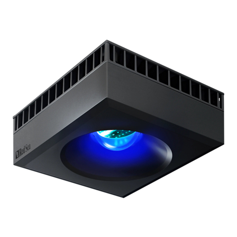
The MAX®S LED lighting system is designed specifically for the MAX®S LED aquariums and should be used in
conjunction with the MAX®S LED power center.
The compete lighting unit is designed to slide easily front/back to give full access to the top of the
aquarium.
The ReefLED™90 modules have a built-in Wi-Fi and must be connected to a smartphone and internet to get the
benefits of all of the features. To set up and program the ReefLED™90 follow the instructions provided.
Programming guidelines:
Photoperiod: Day/moonlight
The day photoperiod should be between 8 – 12 hours with no more than about 9 hours at maximum intensity.
Corals and fish must have daily periods of darkness. Moonlight should be limited to a maximum period of about 4
hours.
Acclimation
To prevent photo-inhibition due to the high intensity of LED lights, an acclimation period is recommended for new
systems or when introducing new corals.
Acclimation will vary for different kinds of corals however it is recommended to allow a period of 8 weeks for
new set-ups.
During the acclimation period look for signs of photo stress and photo-inhibition such as:
• Whitening/Bleaching of the upper section of the tissue (the lower section will continue to show pigments and
zooxanthellae).
• Polyps retraction.
• Gas bubbles inside the soft tissue.
In the event of any of the above symptoms immediately reduce the Acclimation intensity by 20% for about 4
weeks and thereafter increase by 5% per week until maximum intensity is reached.
When introducing new corals to already acclimated systems, start by positioning them at the lower levels of the
aquarium and gradually raising them to their desired position over a period of several weeks. Keep watching for
signs of photo inhibition/stress and if necessary return an affected coral to lower levels for recuperation.

11
MAX®S-Series LED Installation & Operation Manual’s
Power Center
Assemble the Power Center (PC) drawer in the cabinet by laying the drawer on the sliders and push into
position. There are 2 catches on the underside of the drawer that “click” when the drawer is attached
properly to the sliders. To remove the drawer, release the 2 catches on the underside of the drawer and
pull the drawer off of the sliders.
The PC includes 3 individual power strips, each of which can be removed for service without affecting the
functionality of the others. Protected by a resettable thermal circuit breaker which will only neutralize the
specific strip. The left and right strips are identical and provide 5 individually switched outlets on each that
are protected by a resettable thermal circuit breaker which will only neutralize the specific strip. The center
strip is for the LED lighting. The main switch on the front panel shuts down the complete strip.
Connect the main power cable to the inlet socket of the left strip and direct the cable out of left slot on the
back of the drawer. Ensure that all of the switches on the front panel are in the off position. Do not connect
the main power cable to the power until the aquarium and sump are filled with water.
To connect equipment to the PC:
IMPORTANT: Before opening the PC ensure that your hands are dry and that there is no water dripping down
the front glass of the aquarium.
1. Make sure that the lid is in the closed position (pulled to the front of the drawer) and that the drawer
is in its normal operating position. All equipment is attached from the rear of the drawer.
2. Place plugs into the back section of the drawer with the cables running through one of the slots.
3. Open the drawer as far as it will go and slide the lid backwards.
4. Reach into the back of the draw and gently pull the plugs forward.
5. Insert each plug into its designated outlet.
6. Close the lid (pulled to the front of the drawer) and return the draw to its normal operating position.
7. Make sure that all of the cables at the back of the drawer are free to move as the drawer is opened
and closed.
Heaters, Chillers and other accessories
Heaters and Chillers are not provided as a standard part of the MAX®S however preparations have been
made for their installation.
Dedicated power outlets are provided for a heater, chiller and 2 accessories in the Power center.
Chiller: The left hand compartment under the power center has been designed to house a chiller. A gap has
been provided between the base board and door and the rear has been left open to allow for proper airflow
for the chiller to run without overheating. The inlet and outlet pipes of the chiller should pass through the cut
out at the top rear left corner of dividing wall between the sump and chiller compartments.
S-400: Connect the inlet pipe of the chiller to the chiller outlet on the main pump manifold. Place the return
pipe from the chiller into the downpipe chamber of the sump with the return pipe ending under the water.
Once the complete system is operational set the chiller flow valve for a flow of approximately 2000 l/h
(500gph).
S-500: Connect the inlet pipe of the chiller to the chiller outlet on the main pump manifold. Connect the
outlet of the chiller to the inlet of the chiller return pipe that is attached to the rear wall of the sump
compartment. Add an extra piece of flexible pipe from the outlet of the chiller return pipe to the downpipe
chamber of the sump with the flexible pipe ending under the water. Once the complete system is
operational set the chiller flow valve for a flow of approximately 2000 l/h (500gph).
Heaters and other accessories (such as a calcium reactor) can be placed in the accessory compartment
(left side) of the sump. Water to feed accessories can be taken by replacing the ¾” plug in the main pump
manifold with a suitable hose barb.

12
MAX®S-Series LED Installation & Operation Manual’s
S-650: Place a 2400 l/h (600gph) feeding pump for the chiller in the accessory compartment (left side) of
the sump and connect with flexible piping to the inlet of the chiller. Connect the outlet of the chiller to the
inlet of the chiller return pipe that is attached to the rear wall of the sump compartment. Add an extra piece
of flexible pipe from the outlet of the chiller return pipe to the downpipe chamber of the sump with the
flexible pipe ending under the water.
Heaters and other accessories (such as a calcium reactor) can be placed in the accessory compartment.
Water to feed accessories can be taken by replacing the ¾” plug in the main pump manifold with a suitable
hose barb and adjusting the flow as required with the valve.

13
MAX®S-Series LED Installation & Operation Manual’s
Operation
MAX®S Aquarium Flow Dynamics Overview
The MAX®S aquarium is divided into 3 parts: Main Tank, Rear Chamber and Top-up Reservoir.
The main tank and rear chamber are connected by a surface skimmer across the top of most of the length of
the tank and a number of flow holes located along the back wall.
The silent-flow downpipe system includes a transparent funnel with a flow-regulated main downpipe and a
secondary overflow pipe that is 25mm (1”) above the main downpipe. The fine adjustment flow valve allows
for the water level in the rear chamber to be maintained at a constant height without hearing the water
returning to the sump. In the event of a change in flows or blockage in the main downpipe the overflow
pipe will accommodate all of the water flow to the sump. An incorrect setting of the flow valve will be
accompanied by the sound of the water returning to the sump and is an indication that the flow valve needs
adjusting.
When all of the circulation pumps are running and the flow valve is adjusted correctly the water in the main
tank will always be maintained just below the bracing bars but above the external trim so the water line in
the aquarium will never be visible from the outside. The water level in the rear chamber will be maintained
approximately 30mm (1¼”) below the water level in the main tank ensuring a positive surface skimming at
all times. The height of the water in the rear chamber can be monitored through the viewing slot at the top of
the side panel on the right side of the chamber or by lifting the flap above the funnel.
Any loss of water due to evaporation will
cause a drop in the water level of the
sump. The float valve in the main pump
compartment of the sump controls the
automatic replenishment of top-up water from
the reservoir. The reservoir contains water for
approximately 5 days of evaporation. Top-up
water is added to the reservoir at the top left
corner of the rear chamber. The water level
in the reservoir can be monitored through the
viewing slot at the bottom of the side panel
on the left side of the chamber.
In the sump all water passes through 2
mechanical sponge filters before flowing into
the skimmer and accessory chambers. All of
the water then passes through the carbon
filter media before entering the main pump
chamber.
The main pump returns the water to the
aquarium and a regulated portion of the
flow is provided for the skimmer and in the
400/500 also to the chiller.

14
MAX®S-Series LED Installation & Operation Manual’s
Initial Fill
Open the main flow valve (rotate anti-clockwise) to maximum.
Add water to the main tank and rear chamber and when the water is
above the level of the circulation pump outlets switch them on.
Continue adding water to the main tank. Open the cabinet door and
monitor the water level in the sump as it begins to fill. As soon
as there is approximately 15 cm (6”) of water in the main pump
compartment switch on the main pump and stop adding water.
Allow the system to run for a few minutes and try to adjust the flow
valve so that the water level in the rear chamber is approximately at
the dotted line.
Open the valves to the skimmer (initially approximately 50% open) and
any other equipment that takes water from the sump and readjust the flow
valve.
Add more water to the system until the water level in the main pump
chamber of the sump is approximately 20cm (8”).
WARNING: overfilling the sump may cause a flood in the event of an interruption of electricity.
NOTE: It is advisable to do the first fill with fresh water or a weak saltwater solution to check the integrity
of the system and to clear away any chemical residues from production.
Automatic Top-up System
Once the saltwater system is stable and the water height in
the main pump chamber is approximately 20cm (8”) adjust
the angle of the float so that the valve is closed at the desired
water height. Ensure that the Top-up flow valve is fully closed.
Fill the Top-up reservoir with RO water. For easy access to the
fill port of the reservoir raise the rear 4xT5 light unit to the
upright position and fully open the fill port flap.
Disconnect the top-up flow valve from the float valve and
slowly open the flow valve until the top-up water drips at a
rate of approximately 1 drop per second. Reconnect the flow
valve to the float valve.

15
MAX®S-Series LED Installation & Operation Manual’s
Main Downpipe Flow Valve
The main downpipe flow valve provides a very
fine control of the flow rate however after making
adjustments it takes the system a few minutes to
stabilize at the new setting. Once you have established
the approximate setting for the valve make very small
adjustments and wait for a few minutes each time. It
may take a number of occasional adjustments to reach a
stable level. When set properly this system removes all
of the noise of water flowing down to the sump.
Maintenance of flow valve
To disassemble the valve, switch off all of the pumps and
allow the water level in the rear chamber to drop below
the rim of the transparent funnel. Once the main
downpipe is clear of water, remove the 4 rubber
plugs from the corners and unscrew the 4 screws
with the Allan key provided. Maintain the valve
assembly vertical and pull it away from the valve
body. Be careful not to let the screws fall out.
In the event of calcium deposits clean both the
valve body and diaphragm with a weak acidic
solution (e.g. vinegar) and rinse thoroughly after
treatment.
When reassembling the valve assembly on the
body, ensure that all 4 screws are tight enough
to give a watertight seal however do not use
excessive force. Replace the rubber plugs.
To replace the diaphragm rotate the handle
clockwise and when free of the boby remove the
restaining pin. To reassemble rotate the handle in
the oposite direction until the diaphragm is fully retracted.
1. 2.

16
MAX®S-Series LED Installation & Operation Manual’s
Maintenance
The long-term success and health of the inhabitants of your MAX®aquarium depends on you. Proper
planning makes reef care easier to manage and quicker to perform. This will leave you more time for the
real goal: enjoying your aquarium. Care of the tank should follow a regular, logical pattern. Divide the tasks
into daily, weekly and monthly procedures, including equipment checks, feeding, water parameter testing
and adjustments.
You may find it helpful to make a systematic checklist of care activities and keep a log of the activities
performed� Your log does not need to be complicated; you will need to track the following:
• The tank’s parameters – pH, salinity, temperature, etc.
• Information specific to each animal – when you added them, their approximate size, date of death
(it happens in the most successful aquaria!) and possible cause, etc.
• The general appearance of the tank and individual species.
• Equipment changes.
Circulation - Maintain adequate water circulation by checking that the circulation pumps are working well
and are pointed in the right directions. If you notice any regression in currents, check the inlet of each pump
and the outlet nozzles for any obstructions (snails, crabs, carbon chips, etc.).
Protein skimmer functioning - Check the foam production in the collection cup and adjust the water and air
flow valve as required to get stable dry foam.
Water levels - Check daily the water level in the rear chamber and adjust the flow valve as required. Check
the water level in the Top-up reservoir. Check the water level in the sump. Check that the top-up float valve
is operating correctly.
Water temperature control - For optimum conditions a reef aquarium should be maintained at a stable
water temperature in the range of 24-28°C / 76-82°F (the stability of the temperature being more
important than the exact value). Slightly higher temperatures can be tolerated for short periods of time as
long as the change in temperature is steady and not sudden. Monitor the temperature at least twice a day,
looking for dramatic fluctuations.
Avoid temperature differences of more than 2°C / 7°F during the day. During season changes and when
heating or cooling the house, monitor the tank temperature more frequently, adjusting the heater/chiller as
necessary.
Change the carbon filter - Replace the active carbon filter every two months.
Clean the pump impellers and housing - Calcium carbonate builds up on the pump motors. Every 3 months,
submerge each pump in a mixture of hot water and vinegar. Remember to properly turn off and disconnect
each pump.
Micron Filter bags - It is recommended to have at least 3 sets of filter bags.
There are a few options for cleaning the filter bags:
Quick and effective – Spray the outside of the bags with a powerful water jet such as a garden hose to back-
flush the detritus from the felt.
More thorough – soak the bags in bleach or diluted vinegar for 24 hours prior to spraying as above. Rinse
well to remove all chemicals before returning to sump.
The filter bags can also be put in a cold wash in a washing machine with regular detergent or with vinegar
(may require approval from a higher authority).
Surface Skimmer - Remove and clean the combs of the surface skimmer at least once a week to allow
proper water flow and stable water level differentiation between the aquarium and the rear sump.
Periodically soak the combs in a weak acidic solution (vinegar, citric acid) until any calcium carbonate
deposits have dissolved.

17
MAX®S-Series LED Installation & Operation Manual’s
Warranty
Red Sea Aquarium Products Limited Warranty�
The limited warranty sets forth all Red Sea Aquatics (HK) Ltd (Red Sea) responsibilities regarding this product.
There are no other express or implied warranties from Red Sea.
Red Sea warrants your product against defects in materials and workmanship for a period of 12 months,
valid from the date of original purchase and will repair this product free of charge (not including shipping
costs) with new/rebuilt parts. Damage to the aquarium glass or to the florescent tubes is not included. The
precondition for the warranty is that the stipulated set-up routine is observed. In the event that a problem
develops with this product during or after the warranty period, contact your local dealer or Red Sea (at the
company address indicated) for details of your nearest authorized service center.
The warranty is extended only to the original purchaser. Proof of date of purchase will be required before
warranty performance is rendered. This warranty only covers failures due to defects in materials or
workmanship which occur during normal use. It does not cover damage which occurs in shipment or failures
which result from misuse, abuse, neglect, improper installation, operation, mishandling, misapplication,
alteration, modification or service by anyone other than an authorized Red Sea service center.
Red Sea shall not be liable for incidental or consequential damages resulting from the use of this product,
or arising out of any breach of this warranty. All express and implied warranties, including the warranties of
saleability and fitness for particular purpose, are limited to the applicable warranty period set forth above.
These statements do not affect the statutory rights of the consumer.
USA
Some states do not allow the exclusion or limitation of incidental or consequential damages, or limitations on
how long an implied warranty lasts, so the above exclusion or limitations may not apply.
To benefit from product update information and exclusive special offers to registered MAX®owners, please
register your MAX®on-line at redseafish.com

#2759 MAX S-series manual_EN _v2019a
Europe
Red Sea Europe
655 Rue des Frères
Lumière
27130 Verneuil d’Avre et
d’Iton, France
support.fr@redseash.com
Germany & Austria
Red Sea Deutschland
Büro Deutschland
Prinzenallee 7 (Prinzenpark)
40549 Düsseldorf
support.de@redseash.com
UK & Ireland
Red Sea Aquatics (UK) Ltd
PO Box 1237
Cheddar, BS279AG
uk.info@redseash.com
North America
Red Sea U.S.A & Canada
4687 World Houston
Parkway #150
Houston, TX 77032, U�S�A
support.usa@redseash.com
Asia Pacic
Red Sea Aquatics Ltd
2310 Dominion Centre
43-59 Queen’s Road East
Hong Kong
Tel: +86-020-6625 3828
info.china@redseash.com
China
Red Sea Aquatics (GZ) Ltd.
Block A3, No�33 Hongmian Road,
Xinhua Industrial Park,
Huadu District, Guangzhou City,
China, Postal code 510800�
Tel: +86-020-6625 3828
info.china@redseash.com
Other manuals for MAX S-Series
2
This manual suits for next models
4
Table of contents
Other Red Sea Other manuals

Red Sea
Red Sea MAX S-Series User manual

Red Sea
Red Sea REEFER Series User manual

Red Sea
Red Sea Complete Plug & Play MAX E-170 User manual

Red Sea
Red Sea MAX E Series User manual

Red Sea
Red Sea MAX NANO User manual

Red Sea
Red Sea Hydra 26 User manual

Red Sea
Red Sea Referer 350 User manual

Red Sea
Red Sea ReefLED 50 User manual

Red Sea
Red Sea Complete Plug & Play MAX E-170 Quick start guide

Red Sea
Red Sea REEFER DLX 525 User manual