Red Smoke Alarms RHIS User manual

User Manual
Strobe Light and Vibrating Pad
Model RHIS
INTRODUCTION
MAIN FEATURES
IMPORTANT: If you are installing this product for use by others, you must leave this
manual (or a copy of it) for the end user.
Radio Frequency (RF) Pairing technology enables wireless connections between RF
paired products.
In addition to the audible sound from your smoke or heat alarms, the Strobe Light and
Vibrating Pad will be triggered to alert those who may not be able to hear the audible
alarm. The flashing strobe provides a visual warning for waking hours, while the
vibrating pad is designed to be placed under a pillow or a mattress and is suitable for
waking an individual to alert them when an alarm sounds. If placed under a mattress,
ensure the thickness of the mattress does not cushion the pad to the extent it cannot
be felt adequately.
• This products can be wirelessly paired to create a network, meaning if smoke or heat
triggers any alarm in the network, all other networked alarms and ancillary devices
activate.
• RF Strobe Light and Vibrating Pad Bundle provides additional protection when
sound alone may not be enough.
• Wirelessly connects to other Red Smoke Alarms with RF compatibility.
• The Strobe provides a remote low level testing facility for testing paired smoke or
heat alarms, which avoid the need to reach up to the ceiling mounted alarms to test
the system.
• Mains powered with rechargable battery back-up (must be replaced after 5 years).
• The Strobe is suitable for wall mounting with 2 screw fixings or free standing.
• RF interconnected alarm system, designed for the hearing impaired.
Strobe and Vibrating Pad pack contains:
1. Strobe light with integrated control unit (referred to as “strobe”)
2. Vibrating Pad to be placed under pillow or mattress (referred to as ”pad”)
3. AC Mains power adapter, 100-240V, 50-60Hz 0.2A, Output: 12.0V 0.5A 6.0W
4. Replaceable, rechargeable Ni-MH battery
5. Wall fixing screws
1. Plug the Vibrating Pad connector into the
Strobe Light (as shown in fig.1). Route
the wires through the wire guide.
NOTE: The battery is supplied in a discharged or partially
discharged state and will require up to 24 hours of charging
(continuous connection to the mains supply) to ensure that it
is fully charged.
During this period the amber fault LED may flash once every
five seconds to indicate that the battery is low. The following
tests however may be carried out before the charging is
complete.
LED indication:
amber fault LED
1 flash every 5
seconds
amber fault LED
2 flash every 5
seconds
amber fault LED
off
Condition Indicated:
Flat Backup
Battery
Low Backup
Battery
Sufficient
Backup
Battery
Action:
Insufficient battery power to power the strobe,
require charging urgently. Not recommanded
to do the wireless pairing in this period.
Battery power is low, sufficient without AC
mains power. User may do the wireless
pairing in this period but afterward, must
charge up the strobe for 24 hours for safety.
Backup Battery power is sufficient without AC
mains for 72 hours. User may do the wireless
pairing in this period.
For Details, see section “Product Indicator (LEDs)” for details of action required.
2. Remove the battery door at the back. Connect the rechargeable battery, by aligning
the terminals (black wire on left to red wire on right) and pushing the connectors
together.
CAUTION: Connect the battery with mains power disconnected.
3. Place the battery into the recess. The battery
cable needs to be positioned underneath the
battery. Place the cable at the bottom of the
recess with the battery lying over the top with
the text on the battery face down. This will
ensure that the battery is installed correctly.
4. Replace the battery door.
5. Plug the power cable in to the Strobe. Route
the wire through the wire guide (fig.2).
6. Plug the mains adapter into a 230V socket
and turn the power on. The green power LED
on Strobe should illuminate.
NOTE: The Strobe and Vibrating Pad will only connect to Red Smoke or Heat Alarms
with RF compatibility. It cannot be paired with other manufacturers’ products.
PREPARATION: Please ensure you have read and understood this manual before
installing your Strobe Light and Vibrating Pad.
It is recommended that for optiumum protection from fire, one RF Pairing smoke or heat
alarm is fitted in each living room of your home, including all bedrooms.
NOTE: Up to 40 Wireless Pairing enabled smoke alarms, heat alarms and/ or Wireless
Pairing accessories can be wireless paired to a single network.
Ensure all smoke and/or heat alarms to be used are installed, tested and working
correctly as per the instructions in their respective user manuals.
It is recommended that you read through these wireless pairing instructions
before starting. There are two programming methods to connect the strobe to
other Red RF devices:
Method 1: Programming setting the strobe as the master, and let other devices
join the wireless network
Method 2: Programming other devices as the master, and and let the strobe pair
to the wireless network
NOTE: The Strobe Light and Vibrating Pad
requires both an AC (mains) electrical
supply and internal battery for its normal
operation. The battery accompanying this
product is rechargeable and charges when
there is mains power to the Strobe.
After pairing the Strobe and Vibrating Pad into the alarms, test the units individually to
ensure they are connected.
NOTE: The amber fault LED will flash (once per 1 second) if the Vibrating Pad is not
correctly installed.
NOTE: The amber fault LED will flash (twice per 1 second) when no RF device has yet
paired to the strobe. Once the strobe has paired to a RF network, this indication will
automatically switch off.
Once the Strobe and Pad are paired to the detectors, all products can be installed. We
recommend you install smoke and heat alarms before installing the Strobe and Pad.
INSTALLING THE STROBE
AND VIBRATING PADS
CONNECTING THE
BATTERY / MAINS POWER
BATTERY CHARGING INSTRUCTION
WIRELESSLY PAIRING THE STROBE
AND VIBRATING PADS TO WIRELESS
SMOKE / HEAT ALARM
fig.1
1. Place one of your smoke or heat alarms on to its base plate. You will use this
product to pair with the strobe to create a network.
2. Hold the Test button of the Strobe for 10 seconds (fig.3).
3. The red LEDs on the front will continue to illuminate to indicate the strobe is in
wireless pairing mode for 150 seconds.
4. During this period, press pair button 2 times on the smoke or heat alarm to
wirelessly pair the two products. The red LED on the alarm will flash 5 times.
NOTE: User can press the test button of the master to manually switch off the
master’s pairing mode.
5. After pairing the Strobe and Vibrating Pad with the alarm, test the product individu-
ally to ensure they are working and connected.
1. Read the manual instruction of the wireless devices (Red Smoke’s smoke and/or
heat alarm).
NOTE: Find the manual instruction of RF wireless smoke and/or heat alarms from
Red Smoke PTY. Ltd. official website.
2. Find the wireless pairing button of
the wireless device and hold it for 10
seconds.
3. The red LEDs on the front will
continue to illuminate to indicate this
wireless device is in wireless pairing
mode.
4. Press the Test button on the strobe
for 2 times (fig.3). The red LED on
the strobe will flash 5 times.
5. After pairing the strobe and vibrating
pad with the device, test the product
individually to ensure they are
working and connected.
fig.2
fig.3
Test and Pairing Button
Clear the strobe's RF Pairing Memory from the wireless
network
In the event that you need to clear the RF Pairing Memory of
the Strobe from a network (e.g. moving house) you will need
to remove it from the network using the following procedure:

For Details, see section “Product Indicator (LEDs)” for details of action required.
1. Briefly push and release the test button 5 times (fig.3).
2. The red LEDs on the front of the Strobe will illuminate 5 times after you push the
button.
3. Press the test button on the Strobe. It should not cause other wireless paired alarms
to goes off. If the Strobe is still paired, repeat the above procedure.
IMPORTANT: If you wish to remove the Strobe and Vibrating Pad from the wireless
network, it is important to clear the RF memory of all network unit/units and
reconnect all nessecary RF device to a new network. Failure to do so means that the
unit continues to try and communicate with the removed unit, and will result in a
system fault.
Testing the network from the smoke alarm or heat alarm.
Strobe Light: The Strobe will flash and the correspond-
ing red (alarm) LED will also flash.
Vibrating Pad: The Vibrating Pad will vibrate.
Auxiliary (Clock): check section “CLOCK INPUT
SOCKET” for details.
Repeat the procedure with all alarms in the wireless
network.
Testing the network from the Strobe Light
Briefly press the test button for 3 seconds on the Strobe and release. The Strobe will
flash, and the Vibrating Pad will vibrate. At the same time, any alarm that is RF paired
to the network will also go off.
The red LEDs on strobe will flash for 5 seconds and continue to illuminate for 60
seconds, the pad will vibrate for 5 seconds. The test mode will last for 60 seconds. To
deactivate the strobe from the test mode, briefly press the test button once again. This
confirms that all units are wirelessly paired.
Testing
It is recommended that a self-test of all the units in your RF network is carried out
weekly.
In addition the network should also be tested whenever:
TESTING THE STROBE LIGHT AND
VIBRATING PAD WITH SMOKE /
HEAT ALARMS
POSITIONING
UNPLUGGING FROM THE MAINS /
POWER CUT
Where should the Strobe Light and Vibrating Pad be installed?
If you have one Strobe Light and Vibrating Pad, it should be installed in the main room
where you sleep. You may add additional Strobes Lights and Vibrating Pads to the
network and install them in any room where you may need to be alerted in the event
of an alarm. It is important that if you install additional Strobes Lights and Vibrating
Pads you test each of these upon installation to check they have paired to the rest of
the network.
Wireless Range: The wireless range of RF products is over 100 metres in clear
air/clear line of sight.
However it is recommended not to exceed 30m as the maximum distance between
any RF paired smoke alarm or heat alarm and the Strobe light and Vibrating Pad. This
is because the range can be reduced by walls, and other obstructions in the building.
Position the Vibrating Pad:
• Under your pillow or mattress.
• Under a cushion on a chair where you are likely to fall asleep.
• Test and check that the Vibrating Pad can be felt in all circumstances where you may
fall asleep. Ensure it is placed securely and cannot fall out – ideally within the
pillowcase or cushion cover.
Position the Strobe Light:
• Close to a power socket where it can be easily plugged in and the cable does not
create a tripping hazard.
• Where you can see the Strobe flashing from anywhere in the room.
• Where you can see the LEDs on the front of the unit.
NOTE: The Strobe can be fitted to a wall or it can be placed on a table.
CAUTION: Do not put the Strobe and Vibrating Pad:
• Outside the building.
• In a damp or humid area.
• In an area where the temperature could regularly drop below –5°C or regularly rise
above 40°C.
• Anywhere where the units can easily be knocked or damaged.
Standby Mode
The Strobe should be connected to the mains AC supply with the Vibrating Pad
connected, and placed in a suitable position. The green “power” LED on the strobe will
be permanently illuminated
Alarm Mode
Strobe – Flashing strobe and Fire red LED flashing
Pad – Vibration warning
When a RF paired smoke or heat alarm goes into “alarm” mode, the Fire red LED will
illuminate, the Strobe will continuously flash and the Vibrating Pad will continuously
vibrate.
The way in which the Strobe and Pad alerts a warning is the same for both alarm types,
i.e. the Strobe will flash and the Pad will vibrate in exactly the same way, irrespective of
whether the alarm is triggered by a smoke alarm or heat alarm.
NOTE: The Strobe will stop flashing, the red LED will cease to flash and the Vibrating
Pad will stop vibrating when the alarm sending the signal has been reset or has stopped
if the danger is no longer present.
Only reset an alarm if you are certain there is no imminent danger from fire.
Locate Feature
When the network is in alarm mode, pressing the test button on any unit in the network
will silence all other alarms in the network, for a period of 2 minutes, except the alarm
that has sensed smoke or heat. This will enable the instigating alarm to be located.
DANGER: Under no circumstances should this product be immersed in water, or
used in an area where water may come into contact with the product.
Make sure the Strobe is visible from anywhere in the room.
To wall mount the Strobe drill two suitably sized holes 30mm apart, centre to centre,
using the template (fig5.1) (Warning - make sure that you check for electrical cabling
and pipework hidden in the wall before carrying out any drilling).
INSTALLING THE STROBE LIGHT
LIMITATIONS
• The Strobe and Vibrating Pad will not operate in isolation, with non-RF Alarms, or any
alarms made by other manufacturers.
• The separate units making up the Strobe and Vibrating Pad cannot be interchanged
with those of other manufacturers and an attempt to do this may render the whole
system unsafe.
• The Strobe and Vibrating Pad may not respond to the signal from a RF alarm if the
alarm and the Strobe containing the control box are too far apart.
• The Strobe and Vibrating Pad may not respond to the signal from a RF alarm if there
are obstructions that significantly reduce the signal (e.g.: steel reinforcement in
concrete). Always test the operation of the Strobe and Vibrating Pad with all other
alarms and units in the network after any changes to the building structure or in the
position of large items of furniture.
OPERATION
The Strobe and Vibrating Pad is designed to be mains powered. The internal rechargea-
ble battery will still provide power if the mains is disconnected. A fully charged battery
will allow the Strobe and Vibrating Pad to continue to operate for 72 hours. Only use the
battery supplied in the pack or a genuine replacement. Other rechargeable batteries
may damage the equipment or create a safety hazard.
WARNING: When the mains power is disconnected, the green power LED will no
longer illuminate and the amber (Fault) LED will double flash every 5 seconds. Plug the
Strobe back into the mains as soon as possible to recharge the battery and maintain
operation.
If the amber LED is flashing once every 5 seconds when the green power LED is off then
URGENTLY restore power to the unit as battery status is very low, and may fail to
operate in an alarm situation.
NOTE: Once the Strobe is plugged back into the mains, the amber (Fault) LED will
continue to flash twice every 5 seconds until the battery has fully recharged.
See “BATTERY CHARGING INSTRUCTION” for details.
fig5.1
30mm
• An additional alarm or ancillary product is added to the system.
• There are changes to the structure of your property.
• There are significant changes in the position of large items of furniture or electrical
products in your home.
• You replace the battery in any product within the RF network.
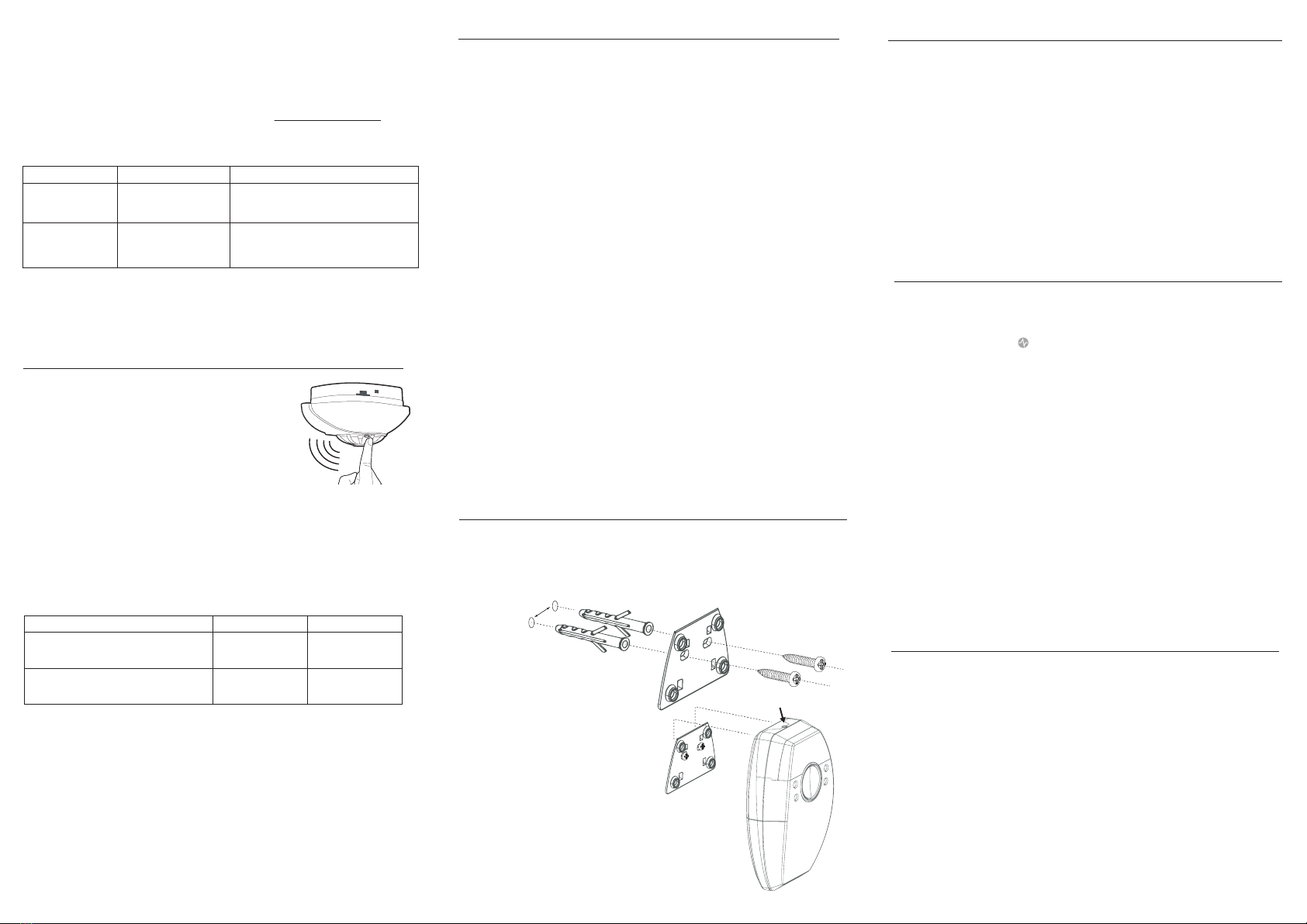
• The Strobe and Vibrating Pad are now ready to be placed into position.
In the pack you will find two screws and
two screw anchors. Push the screw
anchors (if needed) into the drill holes
and secure the screw leaving the heads
protruding so that the face of the head is
5mm away from the wall.
Now hook the strobe onto the mounting
bracket.
If placing the strobe on a table instead of
mounting on the wall, make sure it cannot
be easily knocked or slide off. The green
‘Power’ LED should illuminate continuous-
ly to show that the AC power supply is
connected.
fig5.2
Clock input socket
fig.4
LED indication
amber fault LED
1 flash every 1 second
Condition Indicated: Action:
Reconnect Vibrating Pad to Strobe
Vibrating Pad is not
connected to the strobe.
amber fault LED
2 flash every 1 second
User are required to wireless pair the strobe
with other Red RF devices. Upon successful
networking. This indication will automatically
switch off.
No RF device has been
connected to the strobe
yet.
pads Indication:strobe Indication:
Vibrate for 5 seconds
N/A
Red LEDs flash
rapidly for 5 seconds,
then stay solid
Red LEDs will turn off
Activation / Deactivation
Activate test mode: hold the test button for 3
seconds. (test mode will last for 60 seconds)
Deactivate the test mode: press the test
button for 1 time.

CAUTION: In all circumstances assume that your Strobe situation that has been
triggered by either a smoke or heat alarm.
The type of incident triggering the Strobe and Vibrating Pad to go into alarm is
indicated on the Strobe:
For further fault light Issue relating to battery, see section “BATTERY CHARGING
INSTRUCTION”.
For further fault light Issue relating to RF connection, see section “WIRELESSLY
PAIRING THE STROBE AND VIBRATING PADS TO WIRELESS SMOKE / HEAT
ALARM”
Proceed this set up straight out of the
package:
1. Do not switch “ON” the socket. Plug the
power cord into the back of the strobe. Do
not connect the backup battery to Strobe.
(fig 7.1)
2. Press and hold the test button of the
Strobe (fig 7.2)
3. Switch “ON” the switch. Continue to hold
the test button for about 5 seconds. The
strobe will flash both red LEDS. (fig 7.3)
4. Release the test button and connect the
battery.
NOTE: The strobe will not display fault
system due to disconnected Vibrating Pad.
You can wireless pair the strobe to the RF
network.
If the Vibrating Pad is disconnected but
system still display fault signal, please
operate the above steps again for correct
disconnection.
To remove the Vibrating Pad from RF network:
1. Switch “OFF” the socket power. Disconnect the backup battery. Disconnect Vibrating
Pads from the Strobe Unit (fig.7.4)
2. Press and hold the test button of the Strobe. (fig.7.2)
3. Switch “ON” the socket power. Continue to hold the test button for about 5 seconds.
The strobe will flash both red LEDS. (fig.7.3)
4. Release the test button and connect the battery.
NOTE: The Vibrating Pad can be reconnected at any point and will operate correctly.
What to do in case of a fire in your home
If you have made a family escape plan and practiced it with your family, you have
increased their chances of escaping safely. Go over the following rules with your
children each time you have a fire drill. This will help everyone remember them in case
of a real emergency.
• Don’t panic; stay calm. Your safe escape may depend on thinking clearly and
remembering what you have practiced.
• Notify every member in the residence of the fire. Get out of the house as quickly as
possible. Follow a planned escape route. Do not stop to collect anything or to get
dressed.
• Feel the doors to see if they are hot. If they are hot, do not open them - use an
alternative escape route.
• Stay close to the floor. Smoke and hot gases rise. Cover your nose and mouth with a
cloth (wet if possible). Take short, shallow breaths.
• Keep doors and windows closed. Open them only if you have to in order to escape.
• Meet at your planned meeting place after leaving the house. Carry out a head count.
• Call the fire service on 000 as soon as possible from outside your house. If possible
use a neighbour’s phone or call box rather than a mobile phone (as the location can be
traced from the number if the line is lost). Give the address and your name.
• Never go back inside the building until a member of the fire service has told you it is
safe to do so.
If after proceeding with extreme caution you have been able to confirm that your Strobe
and Vibrating Pad System was triggered by a nuisance alarm (which may occur from
time to time from cooking or other non-emergency situations) you should silence the
alarm that has been triggered. This will stop the Vibrating Pad from vibrating and the
Strobe from flashing. It is important to practice escape plans and show everyone in the
house, including children, what to do in the event of an alarm.
A suitable alarm clock can be connected to the
Strobe through 3.5mm mono jack plug to the
input socket on the strobe(fig.8). The alarm clock
signal is 5 to 24 Volts AC or DC output –
electrically isolated from the mains supply)
When the alarm clock triggers, the vibrating pads
will turn on continuously to wake the person. This
will not activate the internal strobe or other
auxiliary outputs. So, the end-user will know this
is a wake-up call instead of fire.
NOTE: In order for the clock to trigger the
vibrating signal, the vibrating pads must be
connected to the strobe.
WARNING:
DO NOT attempt to repair your Strobe and Vibrating Pad System. Your
wireless Strobe and Vibrating Pad is a sealed AC electrical device, and no attempt
should be made to open the casing on any part of the system. Attempting to open any
case will:
• Damage your system.
• Possibly result in exposure to a potentially lethal electric shock.
• Impair its operation.
• Invalidate your warranty.
If your wireless Strobe and Vibrating Pad is not working correctly and you are unable to
resolve the problem, please contact Technical Support.
The battery provided has been chosen specifically for this application but will need to be
replaced every 5 years under normal operating conditions. If during normal operation
(i.e. connected to the mains supply for at least 72 hours) the amber LED flashes once
every 5 seconds while the green LED is illuminated, contact Technical Support for
advice.
IMPORTANT:
Do not replace with any other type of battery.
REPAIR
STATUS STROBE/
PAD
ACTIVITY
POWER
(GREEN)
FIRE
(RED)
FAULT
(AMBER)
ACTION
NEEDED
PRODUCT INDICATORS (LEDs)
WHAT TO DO IF YOUR STROBE LIGHT
AND VIBRATING PAD GOES INTO
ALARM
WHAT TO DO IN THE EVENT OF A
SMOKE ALARM OR HEAT ALARM
TRIGGERING THE STROBE LIGHT
AND PAD
CLOCK INPUT SOCKET
DISABLING THE VIBRATING PAD
FROM THE STROBE FUNCTION TO
ENABLE THE USE OF STROBE ONLY
Standby
Mode
none required
vibrating
pad is not
connected
to strobe
1 flash
per second
reconnect the vibrating
pad to strobe
No RF
device
paired with
the strobe
2 flashes
per second
wireless pair the strobe
with other Red RF
devices.
Flat Backup
Battery
1 flashes
per 5
seconds
2 flashes
per 5
seconds
Unit Fault flashing
rapidly contact technical
support
(Refer to contact
details)
flash 1 timeflash 1 time flash 1 time
Connect
AC Power none required
flashing
rapidly
illuminated
remains
illuminated
(if AC
power is
connected)
remains
illuminated
(if AC
power is
connected)
remains
illuminated
(if AC
power is
connected)
remains
illuminated
(if AC
power is
connected)
remains
illuminated
(if AC
power is
connected)
remains
illuminated
(if AC
power is
connected)
Fire
Alarm Mode
strobe
flashing /
pad
vibrating
strobe
flashing /
pad
vibrating
rapidly for 5
seconds
alarming on fire
evacuate property
immediately
Activate the test mode
by holding the test
button for 3 seconds.
Deactivate the test
mode by pressing the
test button 1 time.
Fire alert
The Fire (red) LED will flash
DO NOT
SWITCH
“ON”
SOCKET
fig.7.1
SWITCH
“OFF”
SOCKET
fig.7.4
fig.7.2
SWITCH
“ON”
SOCKET
fig.7.3
fig.8
Low Backup
Battery
insufficient battery
power to power the
strobe, require
charging urgently. Not
recommanded to do
the wireless pairing in
this period.
battery power is low,
sufficient without AC
mains power. User
may do the wireless
pairing in this period
but afterward, must
charge up the strobe
for 24 hours for safety.
flashes
rapidly for
5 seconds
and remains
illuminated
for 60
seconds
(if without
deactivation)
remains
illuminated
(if AC
power is
connected)
Strobe in
Test Mode

Red Smoke Alarms PTY. LTD. reserves the right to change specifications,modify
designs and discontinue items without incurring obligation and whilst every effort is
made to ensure that descriptions, specifications and other information in this
catalogue are correct, no warranty is given in respect these of and the company shall
not be liable for any error therein.
© Red Smoke Alarms 2023
This material copyright under Australian and international laws. Except as permitted
under the relevant law, no part of this work may be reproduced by any process without
prior written permission of and acknowledgment to Red Smoke Alarm PTY. LTD..
Contact Details
RED SMOKE ALARMS PTY. LTD.
35 Hitech Drive, Kunda Park QLD 4556
www.redsmokealarms.com.au
1300 316 552
WARRANTY
WARNING: DO NOT ATTEMPT TO OPEN THE HOUSING.
The Strobe and Vibrating Pad are warranty to be free from defects in materials and
workmanships under normal use and service for a period of ten years from manufacture
date (exclude replaceable battery). The company will not be obligated to repair or
replace parts which are found to be in need of repair because of misuse, damage or
alterations that occur after the date of purchase. Send the Strobe and Vibrating Pad with
proof of purchase, postage and return postage prepaid, to local distributor. The liability
of the company arising from the sale of this Strobe and Vibrating Pad shall not in any
case exceed the cost of replacement and in no case shall the company be liable for
consequential loss or damages resulting from the failure of the Strobe and Vibrating
Pad.
RED SMOKE ALARMS PTY. SHALL HAVE NO LIABILITY FOR ANY PERSONAL
INJURY OR PROPERTY DAMAGE, OR ANY SPECIAL INCIDENTAL, CONTINGENT
OR CONSEQUENTIAL DAMAGE OF ANY KIND RESULTING FROM A FIRE. THE
EXCLUSIVE REMEDY FOR BREACH OF THE LIMITED WARRANTY CONTAINED
HEREIN IS THE REPAIR OR REPLACEMENT OF THE DETECTIVE PRODUCT AT
RED SMOKE ALARMS PTY. LTD. OPTION. IN NO CASE SHALL RED SMOKE
ALARMS PTY. LTD.’S LIABILITY UNDER ANY OTHER REMEDY PRESCRIBED BY
LAW EXCEED THE PURCHASE PRICE. YOUR STROBE AND VIBRATING PAD IS
NOT A SUBSTITUTE FOR PROPERTY, DISABILITY, LIFE OR OTHER INSURANCE
OF ANY KIND. APPROPRIATE COVERAGE IS YOUR RESPONSIBILITY. CONSULT
YOUR INSURANCE AGENT.
This does not affect your statutory rights.
This device is only suitable for single occupancy private dwellings only and not intended
for multi occupancy private dwellings or commercial or industrial dwellings.
Waste electrical products should not be disposed of with normal household waste.
Please recycle where facilities exist. Check with your Local Authority or retailer for
recycling advice. New regulation will encourage the recycling of Waste from Electrical
and Electronic Equipment (European "WEEE Directive" effective August 2005).
Popular Security System manuals by other brands

Tunstall
Tunstall smart hub user guide

Lucent Technologies
Lucent Technologies PacketStar user guide

hamilton safe
hamilton safe 5000 series Installation & service manual

CareAlert
CareAlert CA-0813 Operation and instruction manual

Audiovox
Audiovox AXT-800 owner's manual

BASETech
BASETech 1487843 operating instructions