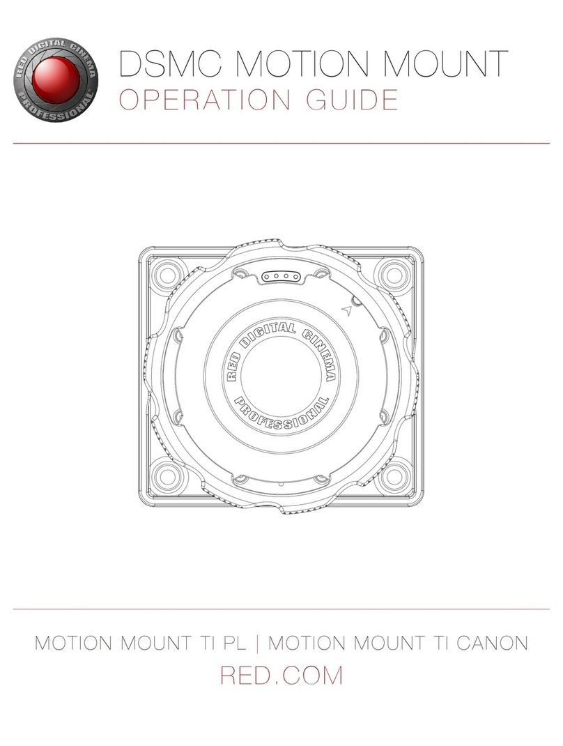
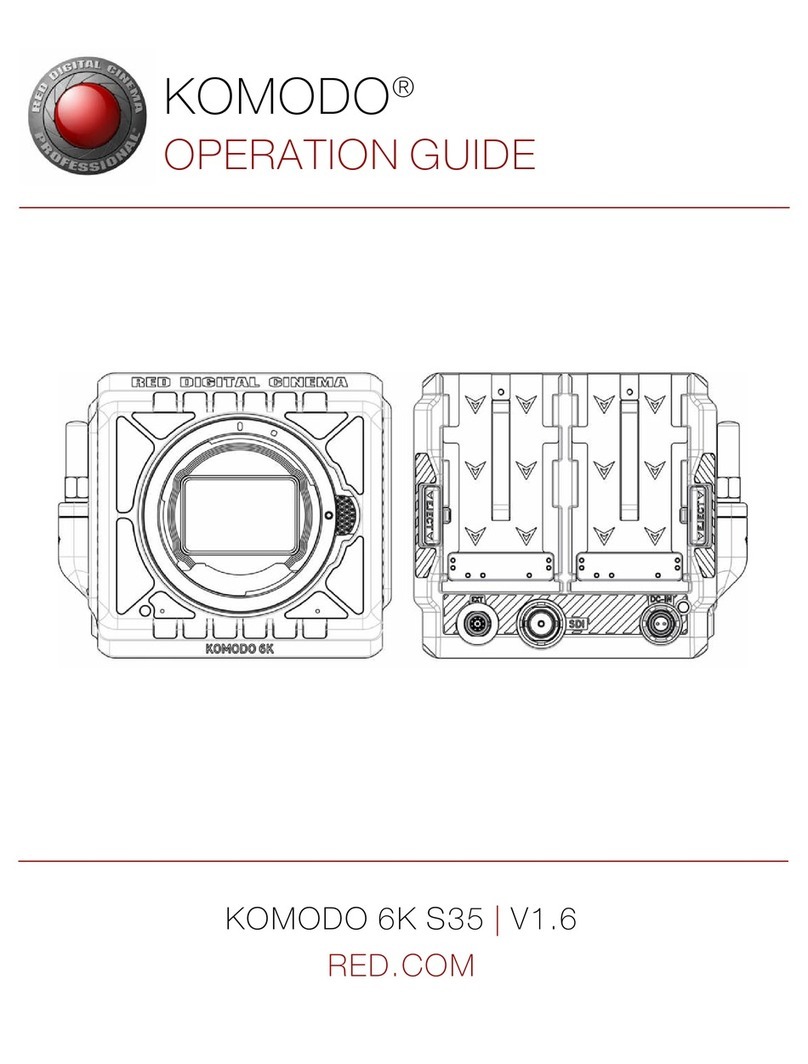
RED Motion mount TI PL User manual

MOTION MOUNT TI PL |MOTION MOUNT TI CANON
RED.COM
RED MOTION MOUNT
OPERATION GUIDE

COPYRIGHT © 2015 RED.COM, INC
RED MOTION MOUNT OPERATION GUIDE
955-0013, REV-K | 2
TABLE OF CONTENTS
Disclaimer 3
Copyright Notice 3
Trademark Disclaimer 3
Compliance Statements 3
Safety Instructions 5
Chapter 1: MOTION MOUNT Introduction 6
Variable ND Filter 6
IR Filter and Linear Polarization 6
Soft Shutter 6
Square Shutter 6
MOTION MOUNT Components 7
Hardware and System Requirements 7
Additional Resources 7
Chapter 2: MOTION MOUNT Installation 8
Lens Mount Alignment 9
Remove a Lens Mount 9
Install the MOTION MOUNT 10
Chapter 3: MOTION MOUNT Operation 12
MOTION MOUNT Settings 12
Access the MOTION MOUNT Menu 12
Neutral Density (ND) 13
MOTION MOUNT Shutter Types 19
Map Keys for MOTION MOUNT Settings 24
Chapter 4: MOTION MOUNT Maintenance 25
Storage Instructions 25
Clean MOTION MOUNT Glass 25
Chapter 5: Troubleshoot the MOTION MOUNT 27
Camera Does Not Recognize the MOTION MOUNT 27
Irregular Out-of-Focus Bokeh Effects and Flare 27
Double Exposures in Captured Footage 28
Appendix A: Technical Specifications 29
RED MOTION MOUNT Ti PL 29
RED MOTION MOUNT Ti Canon 29
Neutral Density and Shutter Angles 30
Maximum Frame Rates 31
Appendix B: MOTION MOUNT Compatibility 32
Compatibility Requirements 32
Compatible PL Lenses and Devices 33
Incompatible PL Lenses and Devices 35
Compatible Canon EF Lenses 35
Non-Linear Editing (NLE) Applications 35

RED MOTION MOUNT OPERATION GUIDE
COPYRIGHT © 2015 RED.COM, INC 955-0013, REV-K | 3
DISCLAIMER
RED has made every effort to provide clear and accurate information
in this document, which is provided solely for the user’s information.
While thought to be accurate, the information in this document is
provided strictly “as is” and RED will not be held responsible for is-
sues arising from typographical errors or user’s interpretation of the
language used herein that is different from that intended by RED.
All safety and general information is subject to change as a result of
changes in local, federal or other applicable laws.
RED reserves the right to revise this document and make changes
from time to time in the content without obligation to notify any per-
son of such revisions or changes. In no event shall RED, its employ-
ees or authorized agents be liable to you for any damages or losses,
direct or indirect, arising from the use of any technical or operational
information contained in this document.
For comments or questions about content in this document, please
COPYRIGHT NOTICE
COPYRIGHT© 2015 RED.COM, INC.
All trademarks, trade names, logos, icons, images, written material,
code, and product names used in association with the accompa-
nying product are the copyrights, trademarks, or other intellectual
property owned and controlled exclusively by RED.COM, INC.
TRADEMARK DISCLAIMER
All other company, brand, and product names are trademarks or
registered trademarks of their respective holders. RED has no affili-
ation to, is not associated with or sponsored by, and has no express
rights in third-party trademarks. ARRI is a registered trademark of
ARRI Group. Zeiss is a registered trademark of Carl Zeiss, Inc. Leica
is a registered trademakr of Leica Microsystems. Canon is a regis-
tered trademark of Canon, U.S.A. Cooke is a registered trademark
of Cooke Optics, Ltd. Fujinon is a registered trademark of Fujinon,
Inc. TORX is a registered trademark of Acument Intellectual Proper-
ties, LLC in the UnitedStates or other countries.
COMPLIANCE STATEMENTS
INDUSTRIAL CANADA EMISSION COMPLIANCE STATEMENTS
This device complies with Industry Canada license-exempt RSS
standards RSS 139 and RSS 210. Operation is subject to the follow-
ing two conditions: (1) this device may not cause interference, and
(2) this device must accept any interference, including interference
that may cause undesired operation of the device.
This Class B digital apparatus complies with Canadian ICES-003.
Le présent appareil est conforme aux CNR d’Industrie Canada ap-
plicables aux appareils radio exempts de licence. L’exploitation est
autorisée aux deux conditions suivantes : (1) l’appareil ne doit pas
produire de brouillage, et (2) l’utilisateur de l’appareil doit accepter
tout brouillage radioélectrique subi, même si le brouillage est sus-
ceptible d’en compromettre le fonctionnement. Cet appareil numéri-
que de la classe B est conforme à la norme NMB-003 du Canada.
FEDERAL COMMUNICATIONS COMMISSION (FCC) STATE-
MENTS
This equipment has been tested and found to
comply with the limits for a Class B digital
device, pursuant to part 15 of the FCC Rules.
These limits are designed to provide reason-
able protection against harmful interference
in a residential installation. This equipment
generates, uses and can radiate radio fre-
quency energy and, if not installed and used
in accordance with the instructions, may cause harmful interference
to radio communications. However, there is no guarantee that inter-
ference will not occur in a particular installation. If this equipment
does cause harmful interference to radio or television reception,
which can be determined by turning the equipment off and on, the
user is encouraged to try to correct the interference by one or more
of the following measures:
Reorient or relocate the receiving antenna.
Increase the separation between the equipment and receiver.
Connect the equipment into an outlet on a circuit different from
that to which the receiver is connected.
Consult the dealer or an experienced radio/TV technician for
help.
In order to maintain compliance with FCC regulations, shielded
cables must be used with this equipment. Operation with non-ap-
proved equipment or unshielded cables is likely to result in interfer-
ence to radio and TV reception. The user is cautioned that changes
and modifications made to the equipment without the approval of
manufacturer could void the users authority to operate this equip-
ment.
NOTE: This device complies with Part 15 of the FCC Rules.
Operations subjected to the following two conditions (1) this device
may not cause harmful interference, and (2) this device must accept
any interference received, including that may cause undesirable in-
terference.
CAUTION: Exposure to Radio Frequency Radia-
tion.
The device shall be used in such a manner that the potential for hu-
man contact is minimized
This equipment complies with FCC radiation exposure limits set
forth for an uncontrolled environment. This equipment should be
installed and operated with a minimum distance of 20 cm between
the radiator and your body.
CAUTION: Regulations of the FCC and FAA
prohibit airborne operation of radio-frequency
wireless devices because there signals could
interfere with critical aircraft instruments.
CAUTION: If the device is changed or modified
without permission from RED, the user may
void his or her authority to operate the equip-
ment.

COPYRIGHT © 2015 RED.COM, INC
RED MOTION MOUNT OPERATION GUIDE
955-0013, REV-K | 4
AUSTRALIA AND NEW ZEALAND STATEMENTS
RED declares that the radio equipment described in this document
comply with the following international standards.
IEC 60065 - Product Safety
ETSI EN 300 328 - Technical requirement for radio equipment
RED declares digital devices described in this document comply
with the following Australian and New Zealand standards.
AS/NZS CISPR 22 – Electromagnetic Interference
AS/NZS 61000.3.2 – Power Line Harmonics
AS/NZS 61000.3.3 – Power Line Flicker
JAPAN STATEMENTS
This is a Class B product based on the
standard of the Voluntary Control Council
for Interference (VCCI) for information tech-
nology equipment. If this equipment is used
near a radio or television receiver in a do-
mestic environment, it may cause radio in-
terference. Install and use the equipment
according to the instruction manual.
EUROPEAN UNION COMPLIANCE STATEMENTS
RED declares that the radio
equipment described in this
document comply with the
R&TTE Directive (1999/5/
EC) issued by the Commis-
sion of the European Com-
munity.
Compliance with this directive implies conformity to the following
European Norms (in brackets are the equivalent international stan-
dards).
EN 60065 (IEC 60065) – Product Safety
ETSI EN 300 328 Technical requirement for radio equipment
ETSI EN 301 489 General EMC requirements for radio equip-
ment.
INFORMATION
Products with the CE marking comply with the EMC Directive
(2004/108/EC) and the Low Voltage Directive (2006/95/EC) issued
by the Commission of the European Community. Compliance with
these directives implies conformity to the following European Prod-
uct Family Standards.
EN 55022 (CISPR 22) – Electromagnetic Interference
EN 55024-1 (CISPR 24) – Electromagnetic Immunity
EN 61000-3-2 (IEC610000-3-2) – Power Line Harmonics
EN 61000-3-3 (IEC610000) – Power Line Flicker
EN 60065 (IEC60065) – Product Safety
WASTE ELECTRICAL AND ELECTRONIC EQUIPMENT (WEEE)
The Waste Electrical and Electronic Equip-
ment (WEEE) mark applies only to countries
within the European Union (EU) and Norway.
This symbol on the product and accompany-
ing documents means that used electrical
and electronic products should not be mixed
with general household waste. For proper
treatment, recovery and recycling, please
take this product to designated collection
points where it will be accepted free of
charge. Alternatively, in some countries you
may be able to return your products to your
local retailer upon purchase of an equivalent
new product.
Disposing of this product correctly will help save valuable resources
and prevent any potential negative effects on human health and the
environment, which could otherwise arise from inappropriate waste
handling. Please contact your local authority for further details of
your nearest designated collection point. Penalties may be appli-
cable for incorrect disposal of this waste, in accordance with you
national legislation.
For business users in the European Union, if you wish to discard
electrical and electronic equipment, please contact your dealer or
supplier for further information.
USAGE RESTRICTIONS FOR PRODUCTS THAT INCORPORATE
REDLINK
Products that fall into this category are denoted
by inclusion of the Class 2 identifier symbol (ex-
clamation mark in a circle) accompanying the CE
Mark on the products regulatory label, example to
the left.
FRANCE
Usage Restrictions - Geographic Area Where Restriction Applies :
France
For mainland France
2.400 - 2.4835 GHz (Channels 1-16) authorized for indoor use
2.400 - 2.454 GHz (Channels 1-10) authorized for outdoor use
Restrictions d’utilisation - Zone géographique où les restrictions
s’appliquent : France
Pour la France métropolitaine
2.400 - 2.4835 GHz (Canaux 1 à 16) autorisé en usage intérieur
2.400 - 2.454 GHz (canaux 1 à 10) autorisé en usage extérieur
NORWAY
This subsection does not apply for the geographical area within a
radius of 20 km from the centre of Ny-Ålesund
Dette gjelder ikke for det geografiske området innenfor en radius av
20 km fra sentrum av Ny-Ålesund
RESPONSIBLE PARTY
RED Digital Cinema
34 Parker
Irvine, CA 92618
USA

RED MOTION MOUNT OPERATION GUIDE
COPYRIGHT © 2015 RED.COM, INC 955-0013, REV-K | 5
SAFETY INSTRUCTIONS
DO NOT use the camera or accessories near water. Avoid ex-
posing your camera to moisture. The unit is not waterproof,
so contact with water could cause permanent damage to the
unit as well as electric shock and serious injury to the user. DO
NOT use the camera in the rain or under other conditions with
high moisture without appropriate protection, and immediately
remove power source if camera or accessories are exposed to
moisture.
WARNING: To reduce the risk of fire or elec-
tric shock, do not expose the camera to
rain or moisture.
DO NOT expose the camera to laser beams, as laser beams
may damage the sensor.
DO NOT expose your camera to excessive vibration or impact
(shock). Be careful not to drop your camera. Internal mecha-
nisms may be damaged by severe shock. Mechanical alignment
of optical elements may be affected by excessive vibration.
ELECTROMAGNETIC INTERFERENCE: The use of devices us-
ing radio or other communication waves may result in the mal-
function or interference with the unit and/or with audio and
video signals.
Clean only using a dry cloth. When cleaning your camera, re-
member that it is not waterproof and moisture can damage
electronic circuitry. DO NOT rinse or immerse any element of
the camera, lens or other accessory, keep them dry at all times.
DO NOT use soaps, detergents, ammonia, alkaline cleaners,
and abrasive cleaning compounds or solvents. These sub-
stances may damage lens coatings and electronic circuitry.
Maintain sufficient ventilation—DO NOT block any ventilation
openings or obstruct cooling fan airflow.
CAUTION: Proper camera ventilation re-
quires a minimum 0.5" (1.25 cm) clearance
between the camera ventilation openings
and external surfaces. Verify that objects
that can block the fan intake and ex-
haust ports do not impede airflow. Failure
to permit adequate airflow may result in
overheating of the camera, degraded op-
eration and in extreme situations, damage
to the camera.
DO NOT operate or store near any heat sources such as radia-
tors, heat registers, stoves, or any other apparatus that pro-
duce heat. Store in a protected, level and ventilated place.
Avoid exposure to temperature extremes, damp, severe vibra-
tion, strong magnetic fields, direct sunlight or local heat sourc-
es during storage. Remove any batteries from the camera be-
fore storage. Recommended storage and usage temperatures
for your camera, lenses and other accessories are:
‒Operating range: 0°C to 40°C (32°F to 104°F)
‒Storage range: –20°C to 50°C (–4°F to 122°F)
If there are any performance issues with your camera or acces-
sories when operating within this temperature range, please file
a support ticket on https://support.red.com.
The DSMC Side Handle, side SSD modules, rear modules, and
lens mounts are NOT HOT SWAPPABLE, meaning you cannot
remove or install them while the camera is turned on. Before
installing or removing any of these accessories, you MUST turn
off the camera. Failure to do so may result in damage to the ac-
cessory and/or camera that will not be covered under warranty.
DO NOT bypass the third prong of the grounding-type plug on
the power cord of the DSMC AC Power Adaptor. A grounding-
type plug has two blades and a third “grounding” prong. The
third prong is provided for your safety. A grounding-type plug
shall be connected to an outlet with a protective earthen con-
nection. If the grounding-type plug does not fit into your outlet,
do not attempt to modify the plug or outlet, consult a qualified
electrician.
Protect all power cords from being pinched, walked on or
driven over by a vehicle. Replace any power cords suspected
of sustaining damage due to crushing or other forms physical
damage.
Products marked with this symbol are
class 2 devices. These devices are not
provided with a grounding type plug.
CAUTION: The power cord plug for the
DSMC AC Power Adaptor is used as the
power disconnect. To disconnect all power
from the DSMC AC Power Adaptor, unplug
the power cord plug from the wall outlet.
During use, the power cord plug should
remain easily accessible at all times.
Lithium-ion batteries may be subject to special handling re-
quirements pursuant to federal and local laws. Please refer to
specific shipping instructions included with your battery re-
garding proper transport of your battery. Do not handle your
battery if it is damaged or leaking. Disposal of batteries must
be in accordance with local environmental regulations. For
example, California law requires that all rechargeable batter-
ies must be recycled by an authorized recycle center. Storing
batteries fully charged or in high temperature conditions may
permanently reduce the life of the battery. Available battery
capacity may also be temporarily lessened after storage in low
temperature conditions.
WARNING: DO NOT expose the battery to
excessive heat.
WARNING: Danger of explosion if an incor-
rect battery is charged with the RED Char-
ger or is used to power the camera and
accessories. Replace only with the same
or equivalent type battery.
CAUTION: Refer all service and repair to
qualified RED service personnel. To reduce
the risk of electric shock, and damage to
the camera or accessories, DO NOT at-
tempt to perform any servicing other than
any procedures that are recommended in
the operating instructions.
INDOOR USE ONLY: Products marked with
this symbol are designed for use indoors
only.

COPYRIGHT © 2015 RED.COM, INC
RED MOTION MOUNT OPERATION GUIDE
955-0013, REV-K | 6
The RED MOTION MOUNT®is a revolutionary and adjustable lens mount system for your camera. The
MOTION MOUNT integrates a global shutter, temporal anti-aliasing soft shutter, and variable neutral density
(ND) system. This enables on-the-fly shutter adjustments to reduce motion blur and temporal aliasing. The ND
filter also includes a linear polarizer and IR filter for improved image color and contrast.
NOTE: HDRx®is not available while the MOTION MOUNT is installed.
NOTE: The MOTION MOUNT is compatible with EPIC, SCARLET®, and WEAPON®cameras.
VARIABLE ND FILTER
The electronic variable ND filter provides adjustable optical density for the camera. The amount of optical
density varies based on the active shutter type. Adjust the ND value using a touchscreen or user keys, without
having to change physical filters.
Soft/Square Shutter: Range is 0.48 to 1.20 (1.60 to 4.00 stops)
ND Only: Range is 0.48 to 2.40 (1.60 to 8.00 stops)
NOTE: While the MOTION MOUNT is installed, the adjustable electronic ND filter provides a minimum light loss
of 1.60 stops (0.48 optical density).
IR FILTER AND LINEAR POLARIZATION
The MOTION MOUNT incorporates an IR-cut filter and new color science, providing accurate and natural
color over a wide range of color temperatures. The IR-cut filter ensures rich, deep shadows in your shots and
minimizes IR contamination at high ND levels, without the need for a separate hot mirror.
The built-in linear polarizer improves image quality by increasing contrast and reducing unwanted glare from
light that passes through the MOTION MOUNT to the image sensor.
SOFT SHUTTER
The MOTION MOUNT Soft shutter performs temporal anti-aliasing in your footage, eliminating sampling rate
issues caused by temporal aliasing. This is commonly referred to as the “wagon-wheel effect”. Effectively,
the MOTION MOUNT improves your images and footage by ensuring smooth and natural motion. As its name
implies, the Soft shutter “softens” the edges of blur, resulting in crisp, smooth motion, and pans.
For more information about temporal anti-aliasing, see the Temporal Aliasing with Cinema article available at
www.red.com/learn/red-101/cinema-temporal-aliasing.
SQUARE SHUTTER
The MOTION MOUNT Square shutter, also referred to as “global shutter,” eliminates rolling shutter artifacts,
such as partial illumination caused by strobes and flashing light. The global shutter ensures uniform exposure
throughout your image, regardless of strobes or motion.
For more information about global shutters, see the Global & Rolling Shutters article available at www.red.com/
learn/red-101/global-rolling-shutter.
01 MOTION MOUNT
INTRODUCTION

RED MOTION MOUNT OPERATION GUIDE
COPYRIGHT © 2015 RED.COM, INC 955-0013, REV-K | 7
MOTION MOUNT COMPONENTS
Each MOTION MOUNT package contains one of the following:
DSMC®RED MOTION MOUNT Ti PL
‒DSMC Mount Body Cap
‒DSMC Mount Back Cap
DSMC RED MOTION MOUNT Ti Canon®
‒DSMC Mount Body Cap
‒DSMC Mount Back Cap
IMPORTANT: If any components are damaged or missing, please file a support ticket at https://support.red.com.
HARDWARE AND SYSTEM REQUIREMENTS
The MOTION MOUNT is compatible with EPIC, SCARLET®, and WEAPON® cameras.
Camera firmware v5.1.14 or later
REDCINE-X PRO®Build 20.0.0 or later
NOTE: RED MOTION MOUNT Ti PL and RED MOTION MOUNT Ti Canon use identical filter and shutter
mechanisms. The only differences between the mounts are the mechanical locking systems and compatible
lenses.
NOTE: The MOTION MOUNT is 0.9 mm longer than the respective DSMC Ti PL Mount and DSMC Canon Mount.
ADDITIONAL RESOURCES
The following resources offer additional information about RED®, the camera system, and the RED community:
RED.com: Check the official RED website for the latest information about RED products.
RED Learn Articles: RED offers in-depth technical articles about RED cameras, post production, and digital
cinematography.
RED.com/downloads: Go to the RED Downloads page to download the latest firmware, operation guides,
and post production software.
Support.red.com: Check the RED SUPPORT site for FAQs, or to file a support ticket.
DSMC Toolkit: Go to the RED Downloads page to download the DSMC Toolkit, which offers many helpful
tools and resources to customize and improve your camera workflow.
Bomb Squad Support: For more information, contact your Bomb Squad representative.
Reduser.net: Discuss all things RED on the REDUSER third-party forum.
MOTION MOUNT Ti PL (left),
MOTION MOUNT Ti Canon (right)

COPYRIGHT © 2015 RED.COM, INC
RED MOTION MOUNT OPERATION GUIDE
955-0013, REV-K | 8
The RED MOTION MOUNT®is installed in the same way as other RED lens mounts. Installation and removal
steps provided in this section apply to the following lens mounts:
ITEM PART NUMBER
DSMC®Mg PL Mount 2.0 725-0024
DSMC Ti PL Mount 725-0022
DSMC Al Canon®Mount 725-0026
DSMC Ti Canon Mount 725-0005
DSMC Al Nikon®Mount 725-0006
DSMC Ti Nikon Mount 725-0007
DSMC Al Leica-M®Mount 725-0008
DSMC MOTION MOUNT Ti PL 725-0012
DSMC MOTION MOUNT Ti Canon 725-0014
For more information on maintenance, go to “MOTION MOUNT Maintenance” on page 25.
WARNING: Lens mounts are NOT HOT SWAPPABLE, meaning you cannot install or remove a lens mount while
the camera is turned on. Before installing or removing the lens mount you MUST turn off the camera. Failure to
do so may result in damage to the lens mount or camera that will not be covered under warranty.
WARNING: Any damage to your camera, lens mount, or other equipment caused by the incorrect removal or
installation of lens mounts is NOT covered under any RED®warranty.
NOTE: DO NOT allow dirt or debris to enter the camera opening during the installation or removal of a lens
mount. Take great care not to drop any screws into the camera opening, as damage may occur to the OLPF.
NOTE: Always avoid physical contact with the MOTION MOUNT glass during installation or removal.
02 MOTION MOUNT
INSTALLATION

RED MOTION MOUNT OPERATION GUIDE
COPYRIGHT © 2015 RED.COM, INC 955-0013, REV-K | 9
LENS MOUNT ALIGNMENT
When installing the MOTION MOUNT, ensure that the lens mount is properly aligned. The forward-facing contact
pins differ between the two (2) mounts. RED MOTION MOUNT Ti PL contacts pins are located on the top of the
mount, while RED MOTION MOUNT Ti Canon contact pins are located on the bottom of the mount.
REMOVE A LENS MOUNT
REQUIRED TOOL: T20 TORX®driver
1. Turn off the camera.
2. Attach the camera to a stable platform or position the camera on a clean and level work surface so that the
lens mount screws are accessible.
3. Remove the lens, as well as any modules, cables, or other accessories that might interfere with removing
the lens mount.
4. Loosen and remove the four (4) M4 x 0.7 x 8 mm lens mount screws in a cross pattern (“X” pattern) using
a T20 TORX driver.
NOTE: Screw removal may require a large handle T20 TORX driver and additional leverage.
NOTE: The DSMC Mg PL Mount 2.0 has captive screws that are not removable from the mount.
MOTION MOUNT Ti PL (left),
MOTION MOUNT Ti Canon (right)
Remove the lens mount screws

COPYRIGHT © 2015 RED.COM, INC
RED MOTION MOUNT OPERATION GUIDE
955-0013, REV-K | 10
5. Remove the lens mount from the camera.
NOTE: When the MOTION MOUNT is not in use the rear glass is blue. During operation the rear glass turns
yellow. If you remove the MOTION MOUNT shortly after operation, the glass turns yellow and develops blue
spots. As the glass cools, it returns to its original blue color. This color transition is typical behavior.
INSTALL THE MOTION MOUNT
REQUIRED TOOL: T20 TORX®driver
Turn off the camera and remove any accessories or cables that may interfere with installation before proceeding.
1. Inspect the gold electrical contact pins on the front of the camera and the gold contact pads on the rear of
the MOTION MOUNT. Ensure that they are free of any contamination.
2. Align the MOTION MOUNT on the front of the camera. The camera connection pins must align with the
MOTION MOUNT pins.
Remove the lens mount
Align MOTION MOUNT pins

RED MOTION MOUNT OPERATION GUIDE
COPYRIGHT © 2015 RED.COM, INC 955-0013, REV-K | 11
3. Replace and loosely tighten the four (4) M4x0.7 x 8 mm lens mount screws in a cross pattern (“X” pattern).
WARNING: DO NOT FULLY TIGHTEN.
4. Tighten the four (4) lens mount screws evenly using a T20 TORX driver in a cross pattern (“X” pattern). DO
NOT exceed 350 in-oz, or damage may occur.
WARNING: DO NOT OVERTIGHTEN.
NOTE: The DSMC Mg PL Mount 2.0 has captive screws that are not removable from the mount.
5. After installation, a hardware rediscover or firmware upgrade may be required. If the MOTION MOUNT is
not recognized, you are unable to access the MOTION MOUNT menu at Menu > Settings > Setup > Lens.
To perform a hardware rediscover, go to Menu > Settings > Maintenance > Rediscover. A system reboot is
required after a hardware rediscover.
NOTE: For more information and troubleshooting, go to “Camera Does Not Recognize the MOTION MOUNT” on
page 27.
NOTE: If you need to replace any screws, please contact your Bomb Squad representative.
Install Screws

COPYRIGHT © 2015 RED.COM, INC
RED MOTION MOUNT OPERATION GUIDE
955-0013, REV-K | 12
MOTION MOUNT SETTINGS
The RED MOTION MOUNT®delivers variable ND and shutter options based on the selected shutter type. The
following shutter types are available in Menu > Settings > Lens > Motion Mount.
ND Only: Disables Soft and Square shutters. The MOTION MOUNT functions only as an ND filter. For more
information, go to “Neutral Density (ND)” on page 13.
Soft: Enables the Soft shutter, softening blur and reduction of temporal aliasing. The MOTION MOUNT
continues to function as an ND filter. For more information, go to “Soft Shutter” on page 20.
Square: Enables the Square shutter, ensuring consistent exposure and smooth motion. The MOTION MOUNT
continues to function as an ND filter. For more information, go to “Square Shutter” on page 22.
The maximum shutter angle is restricted on the “ND Only” shutter type when ND is below 0.60 (2 stops). If the
shutter angle that you want is not available with the selected frame rate, increase the ND value to 0.60 (2 stops)
or more and try again.
NOTE: The ND setting cannot be changed while recording.
NOTE: These instructions are specific to camera firmware version v5.2.28.
ACCESS THE MOTION MOUNT MENU
To adjust MOTION MOUNT settings, follow the instructions below:
NOTE: These menu settings are only accessible when the MOTION MOUNT is installed.
1. Turn on the camera.
2. Go to Menu > Settings > Setup > Lens > Motion Mount.
03 MOTION MOUNT
OPERATION

RED MOTION MOUNT OPERATION GUIDE
COPYRIGHT © 2015 RED.COM, INC 955-0013, REV-K | 13
NEUTRAL DENSITY (ND)
The MOTION MOUNT provides a variable ND filter that incorporates an IR filter and polarizer. You can adjust the
ND setting using the on-screen display, or by mapping the following functions to camera keys:
MOTION MOUNT: Increment ND
MOTION MOUNT: Decrement ND
Variable ND functionality is always enabled when the MOTION MOUNT is installed.
For more information on key mapping, go to “Map Keys for MOTION MOUNT Settings” on page 24.
SELECT NEUTRAL DENSITY (ND) SETTINGS
1. Select an ND value using the ND Value slider.
Alternatively, select the settings box and enter a value that you want.
‒Fraction: Displays the neutral density value as a fraction of light transmission.
‒Density: Displays the neutral density value as an optical density value.
‒Stop: Displays the neutral density value as a stop loss.
2. Select an ND Increment Size.
3. If you select Custom, enter the new increment size in the field next to the ND Increment Size drop-down
menu. You can select any increment in the range 0.01 to 4.00 stops.
NOTE: When an ND value over 4.00 stops is selected while in “ND Only,” the ND value on the main screen
overlay turns yellow. The following message also displays in the MOTION MOUNT menu screen: “High ND
with wide apertures may cause bokeh asymmetry”.
For more information on bokeh asymmetry, go to “Out-of-Focus Field Modification” on page 15.

COPYRIGHT © 2015 RED.COM, INC
RED MOTION MOUNT OPERATION GUIDE
955-0013, REV-K | 14
NEUTRAL DENSITY (ND) RANGE
The table below provides the available fraction values, optical density values, and stop losses. The values
provided are in increments of 1/2 and 1/3 stops.
The available ND range is based on the currently selected shutter type.
ND Only: The available optical density range for “ND Only” is 0.48 to 2.40 (1.60 to 8.00 stops).
Soft: The available optical density range for “Soft” is 0.48 to 1.20 (1.60 to 4.00 stops).
Square: The available optical density range for “Square” is 0.48 to 1.20 (1.60 to 4.00 stops).
ND VALUES SHUTTER TYPES
FRACTION DENSITY STOPS ND ONLY SOFT/SQUARE
1/3.03 0.48 1.60 √ √
1/3.18 0.50 1.67 √ √
1/4.00 0.60 2.00 √ √
1/5.06 0.70 2.34 √ √
1/5.66 0.75 2.50 √ √
1/6.36 0.80 2.67 √ √
1/8.00 0.90 3.00 √ √
1/10.13 1.01 3.34 √ √
1/11.31 1.05 3.50 √ √
1/12.73 1.10 3.67 √ √
1/16.00 1.20 4.00 √ √
1/20.25 1.31 4.34 √X
1/22.63 1.35 4.50 √X
1/25.46 1.41 4.67 √X
1/32.00 1.51 5.00 √X
1/40.50 1.61 5.34 √X
1/45.25 1.66 5.50 √X
1/50.91 1.71 5.67 √X
1/64.00 1.81 6.00 √X
1/81.01 1.91 6.34 √X
1/90.51 1.96 6.50 √X
1/101.83 2.01 6.67 √X
1/128.00 2.11 7.00 √X
1/162.02 2.21 7.34 √X
1/181.02 2.26 7.50 √X
1/203.66 2.31 7.67 √X
1/256.00 2.40 8.00 √X

RED MOTION MOUNT OPERATION GUIDE
COPYRIGHT © 2015 RED.COM, INC 955-0013, REV-K | 15
OUT-OF-FOCUS FIELD MODIFICATION
Use of “ND Only” with a high ND value and wide aperture may cause unwanted results, including distortion or
flaring in the out-of-focus field. In some instances, vignetting may also occur at the edge of the image. This is
typical when using lenses with smaller image circles. RED recommends that you do not exceed 4.00 stops of
ND when shooting with wide apertures.
NOTE: For instance, if the MOTION MOUNT is set to 8.00 stops of ND, and the lens is set to T1.8, instead of
the normal circular bokeh pattern, the out-of-focus area may have unwanted or intense flare.
AVOID FLARE AND DISTORTION
Use the following tips to avoid or dramatically reduce flare and distortion.
Increase T-Stop to T4.0 or greater: Increase the T-Stop to T4.0 or greater to dramatically reduce bokeh
distortion.
Reduce ND setting: Reduce the ND setting to five (5) stops or less to produce a more symmetrical bokeh.
Install a traditional ND filter: Use a traditional ND filter if a shot requires a wide aperture (to limit depth-of-
field) and also requires eight (8) stops of ND. Adjust the MOTION MOUNT to four (4) stops of ND and install
an ND filter. This removes bokeh distortion and flare, and also enables the use of the Soft and Square
shutter types.
NOTE: Effects of flare and distortion are negligible at apertures greater than T4.0. Flare and distortion may vary
based on the lens. RED recommends testing each lens in conjunction with the MOTION MOUNT before an
important shoot.
NOTE: Selecting an ND value over 4.00 stops in “ND Only” results in the ND value on the main screen overlay
turning yellow. The following message displays on the MOTION MOUNT menu: “High ND with wide apertures
may cause bokeh asymmetry”.

COPYRIGHT © 2015 RED.COM, INC
RED MOTION MOUNT OPERATION GUIDE
955-0013, REV-K | 16
DISPLAY EFFECTIVE ISO
When using any ND filter, including the MOTION MOUNT, the effective ISO is reduced because the ND filter
reduces light transmission to the sensor. To display the effective ISO (on the main screen) and native camera
sensor ISO (in the ISO/FLUT®screen), follow the instructions below:
1. Go to Menu > Settings > Display > Modes > Lens.
2. Select the MOTION MOUNT ISO Pull setting that you want:
‒On: Displays the effective ISO.
‒Off: Displays actual ISO.
3. Select Close to return to the main screen.
The effective ISO displays in yellow.

RED MOTION MOUNT OPERATION GUIDE
COPYRIGHT © 2015 RED.COM, INC 955-0013, REV-K | 17
4. Go to Menu > Settings > Look > ISO/FLUT, or select ISO in the Upper Status Row (Basic Menu).
5. Select an ISO value on the slider.
NOTE: Remember, changing the effective ISO changes the native ISO of the camera and NOT the ND value.
To view or change the native ISO, press and hold the ISO value to access the Advanced ISO menu. The
native ISO is the first value.
NOTE: RED®recommends that you follow standard exposure best practices and select your ISO value based
on the native ISO.

COPYRIGHT © 2015 RED.COM, INC
RED MOTION MOUNT OPERATION GUIDE
955-0013, REV-K | 18
DISPLAY NEUTRAL DENSITY (ND) SETTINGS
You can configure how the ND settings display in the graphical user interface (GUI).
1. Go to Menu > Settings > Display > Modes > Lens.
2. Select one of the following MOTION MOUNT ND display settings:
‒Fraction: Displays the neutral density value as a fraction of light transmission.
‒Density: Displays the neutral density value as an optical density value.
‒Stop: Displays the neutral density value as a stop loss.
3. Select Close to exit.
The ND value displays in the top left corner of the Live Action Area on the GUI.
NOTE: Using a high ND with wide apertures may cause asymmetrical bokeh. If you select an ND value over
4.00 stops with “ND Only” selected, the ND value on the main screen overlay turns yellow. A warning
message also displays in the MOTION MOUNT menu on the camera. For more information about bokeh
asymmetry, go to “Out-of-Focus Field Modification” on page 15.

RED MOTION MOUNT OPERATION GUIDE
COPYRIGHT © 2015 RED.COM, INC 955-0013, REV-K | 19
MOTION MOUNT SHUTTER TYPES
Based on the selected shutter type, the MOTION MOUNT overrides control of all shutter operations. The
MOTION MOUNT can operate at frame rates up to 109.98 FPS.
Use the table below to help determine which MOTION MOUNT shutter type to use:
SHUTTER TYPE ARTIFACTS
ROLLING SHUTTER TEMPORAL ALIASING
SOFT SHUTTER None Dramatically reduced
SQUARE SHUTTER None No effect
SELECT MOTION MOUNT SHUTTER TYPE AND SETTINGS
1. Go to Menu > Settings > Setup > Lens > Motion Mount.
2. Select one of the following shutter types from the Shutter Type drop-down menu:
‒Soft: For more information, go to “Soft Shutter” on page 20.
‒Square: For more information, go to “Square Shutter” on page 22.

COPYRIGHT © 2015 RED.COM, INC
RED MOTION MOUNT OPERATION GUIDE
955-0013, REV-K | 20
3. Select a Shutter Angle or Int. Time (Integration Time).
SOFT SHUTTER
The MOTION MOUNT Soft shutter is a breakthrough for cinematography, using a liquid crystal shutter to solve
CMOS rolling and global shutter problems. Different from a standard global shutter, the Soft shutter causes the
liquid crystal to rapidly ramp from opaque to clear in a rounded wave. This exposes the sensor to light, taking
many discrete captures of the scene. This technique eliminates the effects of temporal aliasing and reduces
rolling shutter artifacts.
Temporal Aliasing Advantages:
Shows correct direction of rotation of cyclical motion, such as rotating propellers.
Softens blur while preserving clarity.
Reduces judder while panning.
Renders movement accurately and naturally.
Reduces flickering without requiring continuous or synchronized lighting.
Rolling Shutter Advantages:
Reduces striping or tearing artifacts from uncontrolled strobes and flashes.
Reduces skew, also known as the “jello” effect, so that fast-moving subjects are not angled or sheared.
Ensures that images are not blurred or wobbled due to rapid camera movements.
SOFT SHUTTER FRAME RATES
You can use the MOTION MOUNT shutter at frame rates up to 109.98 FPS, but the Soft shutter is most effective
at reducing temporal aliasing artifacts and rolling shutter artifacts at lower frame rates.
SOFT SHUTTER ANGLE
The Soft shutter angle ranges from 62.1° to 194.4°. The available shutter angle range at any given time
depends on the selected frame rate.
For the most natural and realistic motion, use a Soft shutter angle of 194.4°. Then, adjust the shutter angle if
necessary.
Other manuals for Motion mount TI PL
1
This manual suits for next models
1
Table of contents
Other RED Camera Accessories manuals